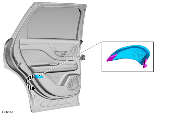
Lincoln Corsair: Rear Suspension / Removal and Installation - Wheel Knuckle - FWD
Lincoln Corsair 2020-2026 Service Manual / Chassis / Suspension / Rear Suspension / Removal and Installation - Wheel Knuckle - FWD
Special Tool(s) / General Equipment
| Vehicle/Axle Stands |
Removal
-
Remove the rear wheel bearing and wheel hub.
Refer to: Wheel Bearing and Wheel Hub - FWD (204-02 Rear Suspension, Removal and Installation).
-
Remove the rear toe link.
Refer to: Toe Link (204-02 Rear Suspension, Removal and Installation).
-
Raise the suspension to the curb height.
Use the General Equipment: Vehicle/Axle Stands
 |
-
Remove the bolts and the rear brake shield.
 |
-
Remove the rear shock absorber lower bolt and position the rear shock absorber.
 |
-
Remove the rear wheel knuckle.
-
Remove and discard the lower arm-to-wheel knuckle bolt and nut.
-
Remove and discard the upper arm-to-wheel knuckle bolt.
-
Remove and discard the lower arm-to-wheel knuckle bolt and nut.
 |
Installation
-
NOTICE: Tighten the suspension bushing fasteners with the suspension loaded or with the weight of the vehicle resting on the wheels and tires, otherwise incorrect clamp load and bushing damage may occur.
NOTE: Make sure that the new bolts and nut are installed.
-
Install the new lower arm-to-wheel knuckle bolt and nut. Tighten the nut.
Torque: 203 lb.ft (275 Nm)
-
Position the wheel knuckle and install the new upper arm-to-wheel knuckle bolt.
Torque:
Stage 1: 98 lb.ft (133 Nm)
Stage 2: 120°
-
Install the new lower arm-to-wheel knuckle bolt and nut. Tighten the nut.
 |
-
Position the rear shock absorber and install the shock absorber lower bolt.
Torque: 129 lb.ft (175 Nm)
|
-
Install the rear brake shield and the bolts.
Torque: 80 lb.in (9 Nm)
|
-
Install the rear toe link.
Refer to: Toe Link (204-02 Rear Suspension, Removal and Installation).
-
Install the rear wheel bearing and wheel hub.
Refer to: Wheel Bearing and Wheel Hub - FWD (204-02 Rear Suspension, Removal and Installation).
 Removal and Installation - Wheel Knuckle - AWD
Special Tool(s) /
General Equipment
Transmission Jack
Vehicle/Axle Stands
Removal
Remove the rear wheel bearing and wheel hub...
 Removal and Installation - Wheel Studs
Special Tool(s) /
General Equipment
Hydraulic Press
Removal
Remove the wheel bearing and wheel hub.
Refer to: Wheel Bearing and Wheel Hub - AWD (204-02 Rear Suspension, Removal and Installation)...
Other information:
Lincoln Corsair 2020-2026 Service Manual: General Procedures - Seat Heater Mat Installation
Repair NOTE: Click here to view a video version of the seat heater mat removal and installation. View NOTE: Always install a new heater mat. NOTE: During installation, it is allowable to adhere a new heater mat to any adhesive left behind on the foam...
Lincoln Corsair 2020-2026 Service Manual: Removal and Installation - Valve Cover
Special Tool(s) / General Equipment 205-153 (T80T-4000-W) Handle 303-1687Installer, VCT Solenoid Seal Materials Name Specification Motorcraft® High Performance Engine RTV SiliconeTA-357 WSE-M4G323-A6 Removal NOTICE: During engine repair procedures, cleanliness is extremely important...
Categories
- Manuals Home
- 1st Generation Lincoln Corsair Owners Manual
- 1st Generation Lincoln Corsair Service Manual
- Programming the Garage Door Opener to Your Garage Door Opener Motor
- Child Safety Locks
- Programming the Garage Door Opener to Your Hand-Held Transmitter
- New on site
- Most important about car
Keyless Starting
Note: The keyless starting system may not function if the key is close to metal objects or electronic devices such as cellular phones.
Note: A valid key must be located inside your vehicle to switch the ignition on and start the engine.
Ignition Modes
Copyright © 2026 www.licorsair.com