Lincoln Corsair: Automatic Transmission - 8-Speed Automatic Transmission – 8F35/8F40 / Removal and Installation - Transmission
Special Tool(s) /
General Equipment
 |
303-F070
Support Bar, Engine
TKIT-1999A-F/LT
TKIT-1999A-FM/FLM |
 |
307-566
Retainer, Torque Converter
TKIT-2006C-FFMFLM
TKIT-2006C-LM
TKIT-2006C-ROW |
| Magnetic Socket |
| Transmission Jack |
| Retaining Strap |
Materials
| Name |
Specification |
Motorcraft® Multi-Purpose Grease Spray
XL-5-A |
ESB-M1C93-B
|
Motorcraft® MERCON® ULV Automatic Transmission Fluid
XT-12-QULV |
WSS-M2C949-A,
MERCON® ULV
|
Removal
All vehicles
-
With the vehicle in NEUTRAL, position it on a hoist.
Refer to: Jacking and Lifting - Overview (100-02 Jacking and Lifting, Description and Operation).
-
Remove the following items:
-
Remove the battery tray.
Refer to: Battery Tray - 2.0L EcoBoost (177kW/240PS) – MI4/2.3L
EcoBoost (199kW/270PS) (414-01 Battery, Mounting and Cables, Removal and
Installation).
-
Remove the air cleaner outlet pipe.
Refer to: Air Cleaner Outlet Pipe (303-12A Intake Air Distribution and
Filtering - 2.0L EcoBoost (177kW/240PS) – MI4, Removal and
Installation).
Refer to: Air Cleaner Outlet Pipe (303-12B Intake Air Distribution and
Filtering - 2.3L EcoBoost (199kW/270PS), Removal and Installation).
-
Remove the cowl panel.
Refer to: Cowl Panel Grille (501-02 Front End Body Panels, Removal and Installation).
-
Remove the front subframe.
Refer to: Front Subframe (502-00 Uni-Body, Subframe and Mounting System, Removal and Installation).
-
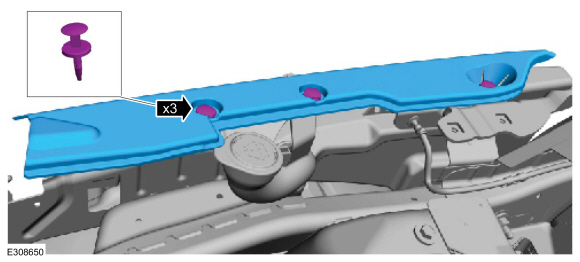
Remove the bolts, pin-type retainer and the RH cowl cover.
-
Remove the bolts, pin-type retainer and the LH cowl cover.
-
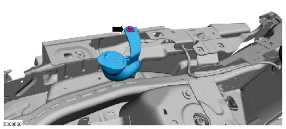
Remove the bolt and position the ground cable aside.
-
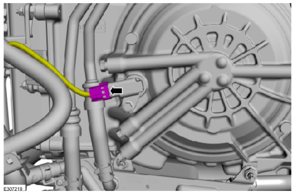
Disconnect the start/stop accumulator solenoid electrical connector.
-
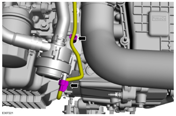
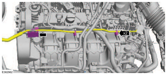
Remove the nuts and position the coolant valve and hoses aside and secure.
-
-
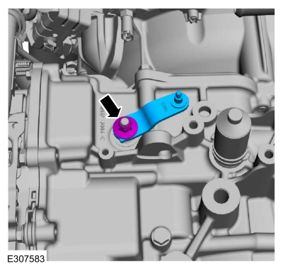
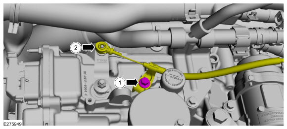
Disconnect the manual park release cable from the manual control lever.
-
Remove the bolt and position the manual park release cable aside.
-
Remove the manual park release lever.
-
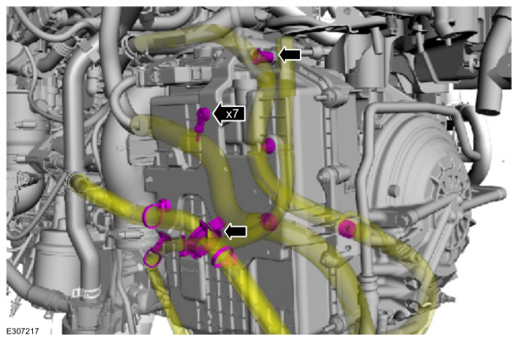
Remove the retainers and position aside the wire harness.
-
Disconnect the coolant pump electrical connector and remove the wire harness retainer.
-
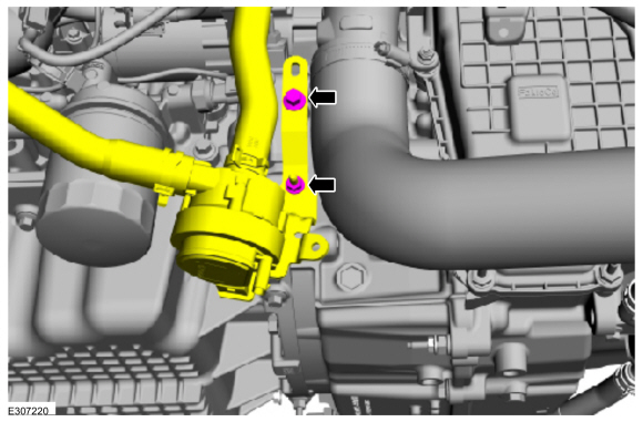
Remove the nut and bolt, position aside the start/stop coolant pump.
-
NOTICE:
When removing any turbocharger air intake
system components, make sure to cover any open ports to prevent debris
from entering the system. The turbocharger compressor vanes can be
damaged by even the smallest particles. All components need to be
inspected and cleaned prior to installation or reassembly.
-
Release the CAC (charge air cooler) hose clip.
-
Loosen the clamp and remove the outlet CAC hose.
-
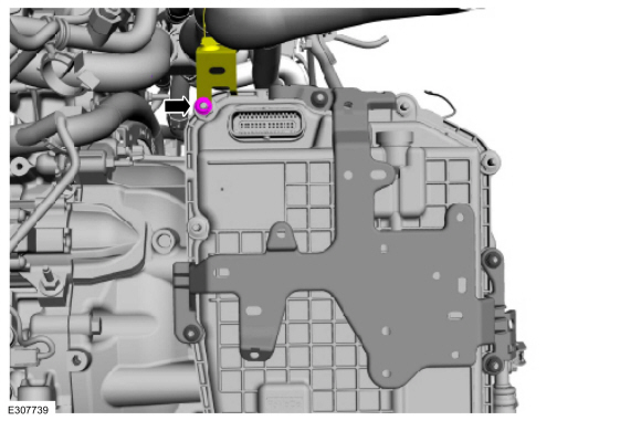
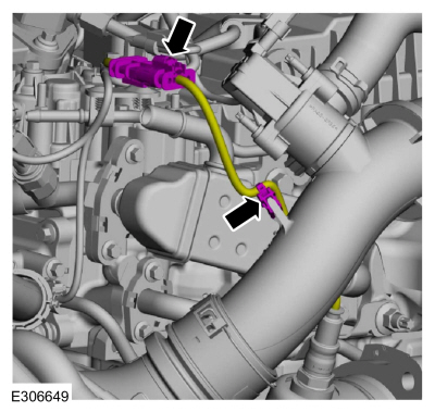
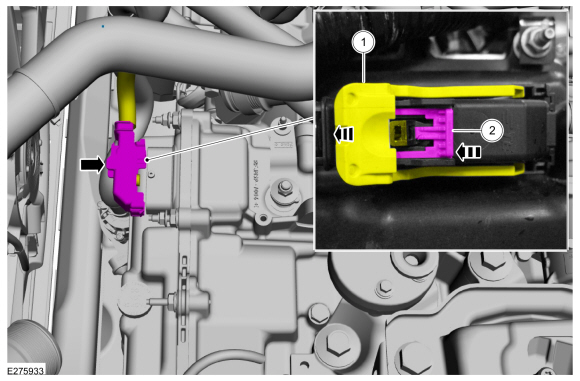
Disconnect transmission connector.
-
Slide the locking clip.
-
Press the tab.
-
While pressing the tab, rotate the connector latch.
-
Disconnect the retainers and position aside the wire harnesses and coolant hose.
-
Disconnect the TSS/ISSA TSS sensor electrical connector.
-
Remove the nut and position aside the radiator hose support.
-
Drain the cooling system.
Refer to: Engine Cooling System Draining, Vacuum Filling and Bleeding
(303-03A Engine Cooling - 2.0L EcoBoost (177kW/240PS) – MI4, General
Procedures).
Refer to: Engine Cooling System Draining, Vacuum Filling and Bleeding
(303-03B Engine Cooling - 2.3L EcoBoost (199kW/270PS), General
Procedures).
-
Release the clamps and position aside the radiator and heater hose.
-
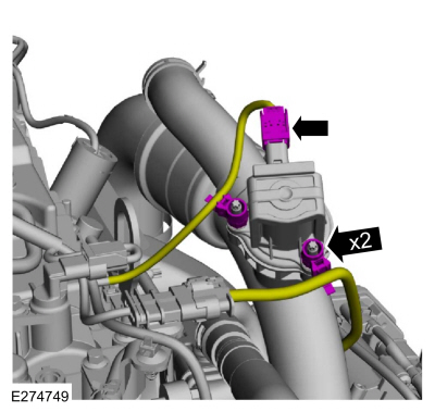
Disconnect the CAC pipe bypass valve electrical connector and wire retainers.
-
NOTICE:
When removing any turbocharger air intake
system components, make sure to cover any open ports to prevent debris
from entering the system. The turbocharger compressor vanes can be
damaged by even the smallest particles. All components need to be
inspected and cleaned prior to installation or reassembly.
Loosen the clamps and remove the CAC hose.
-
Disconnect the HO2S electrical connector and retainer.
-
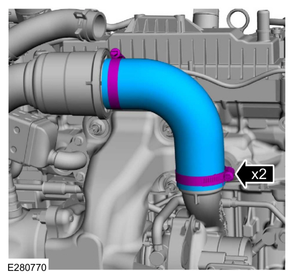
NOTICE:
When removing any turbocharger air intake
system components, make sure to cover any open ports to prevent debris
from entering the system. The turbocharger compressor vanes can be
damaged by even the smallest particles. All components need to be
inspected and cleaned prior to installation or reassembly.
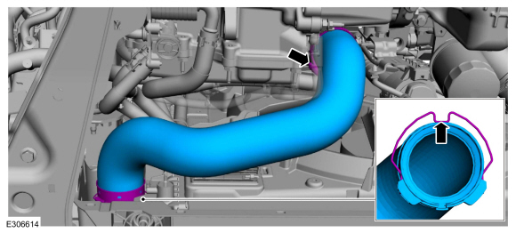
Release the clip and remove the CAC pipe.
-
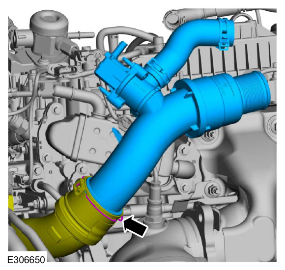
NOTICE:
When removing any turbocharger air intake
system components, make sure to cover any open ports to prevent debris
from entering the system. The turbocharger compressor vanes can be
damaged by even the smallest particles. All components need to be
inspected and cleaned prior to installation or reassembly.
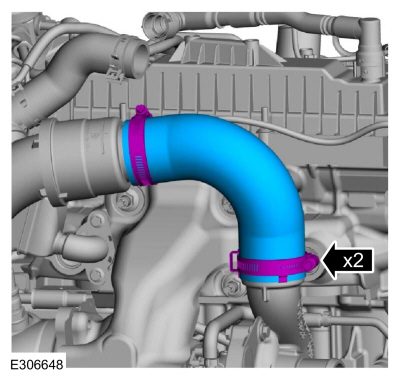
Release the clamp and remove the CAC intake pipe from the thermostat housing and detach the retainer.
-
NOTE:
If transmission disassembly or installation of a
new transmission is necessary, drain the transmission fluid.
Drain the transmission fluid.
Torque:
106 lb.in (12 Nm)
Vehicles with front wheel drive (FWD)
-
Remove the LH front halfshaft
Refer to: Front Halfshaft LH (205-04 Front Drive Halfshafts, Removal and Installation).
-
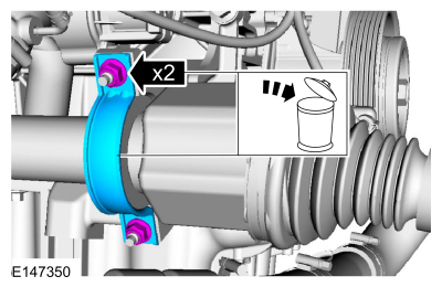
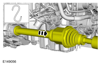
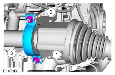
Remove and discard the halfshaft retaining strap and nuts.
-
Position the RH halfshaft aside and support with a length of mechanics wire.
-
Remove the nuts and the bracket.
All wheel drive (AWD)
-
Remove the Power Transfer Unit (PTU) 2.0 EcoBoost engine.
Refer to: Power Transfer Unit - Vehicles With: Power Transfer Unit
Oil-to-Coolant Cooler (307-07B Power Transfer Unit - 2.0L EcoBoost
(177kW/240PS) – MI4, Removal).
Refer to: Power Transfer Unit - Vehicles Without: Power Transfer Unit
Oil-to-Coolant Cooler (307-07B Power Transfer Unit - 2.0L EcoBoost
(177kW/240PS) – MI4, Removal).
-
Remove the Power Transfer Unit (PTU) 2.3 EcoBoost engine.
Refer to: Power Transfer Unit - Vehicles With: Power Transfer Unit
Oil-to-Coolant Cooler (307-07C Power Transfer Unit - 2.3L EcoBoost
(199kW/270PS), Removal).
Refer to: Power Transfer Unit - Vehicles Without: Power Transfer Unit
Oil-to-Coolant Cooler (307-07C Power Transfer Unit - 2.3L EcoBoost
(199kW/270PS), Removal).
All vehicles
-
Remove the starter motor.
Refer to: Starter Motor (303-06A Starting System - 2.0L EcoBoost (177kW/240PS) – MI4, Removal and Installation).
Refer to: Starter Motor (303-06B Starting System - 2.3L EcoBoost (199kW/270PS), Removal and Installation).
-
Remove the stater motor isolator.
-
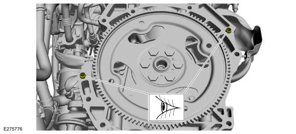
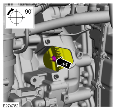
NOTE:
Only rotate the crankshaft in a clockwise direction.
-
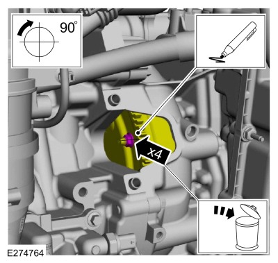
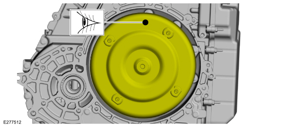
Index mark one stud and the flexplate for assembly reference.
-
Remove and discard the torque converter nuts.
Use the General Equipment: Magnetic Socket
-
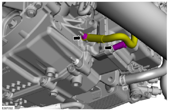
NOTE:
Be prepared to collect escaping fluid.
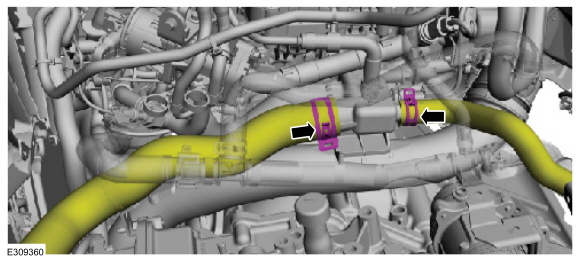
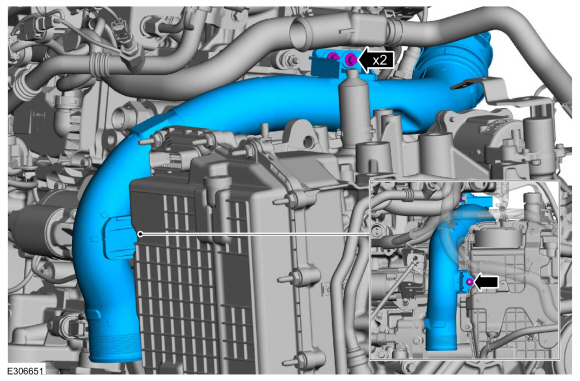
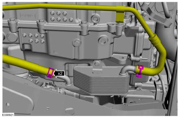
Release the hose clamps and disconnect the transmission fluid warmer coolant hoses.
-
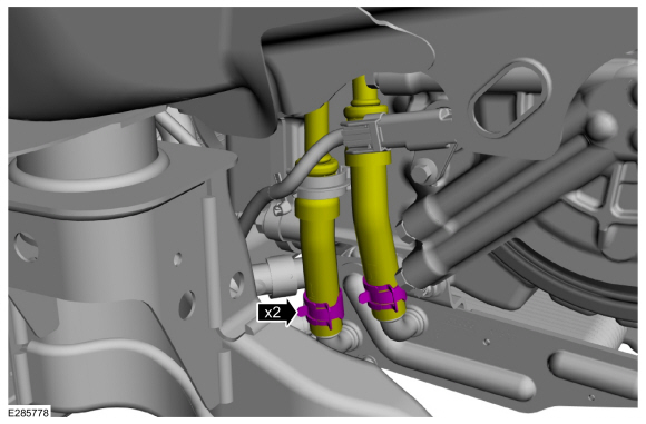
NOTE:
Be prepared to collect escaping fluid.
Release the clamps and disconnect the transmission fluid cooler tubes from the transmission fluid warmer.
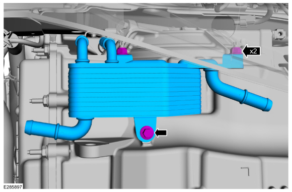
-
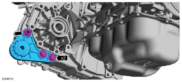
Remove the nuts, the bolt and the transmission fluid warmer.
-
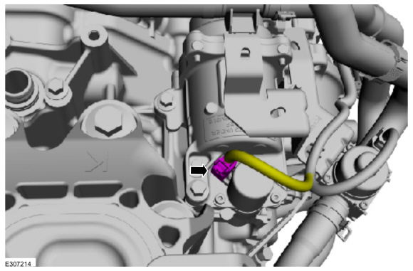
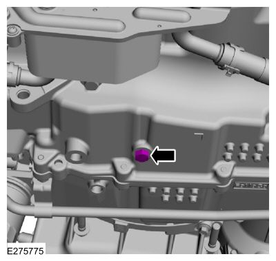
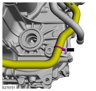
Disconnect the coolant hose from transmission.
-
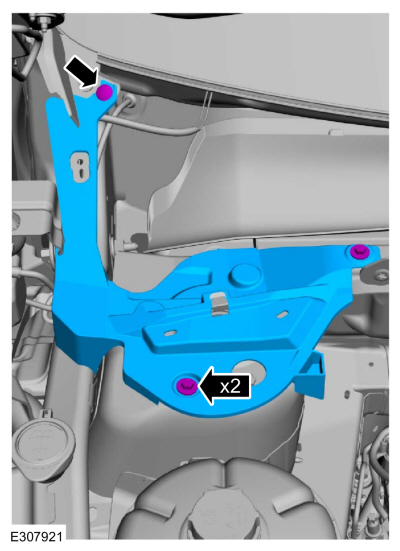
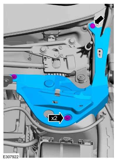
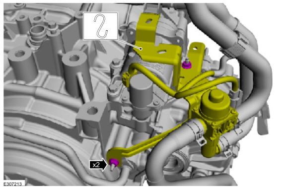
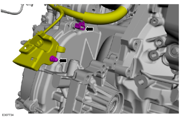
Remove the retainers, position aside the wire harness and bracket.
-
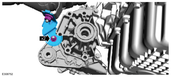
NOTE:
If transmission disassembly or installation of a
new transmission is necessary, remove the roll restrictor bracket.
Remove the bolts and studbolt, remove the bracket.
-
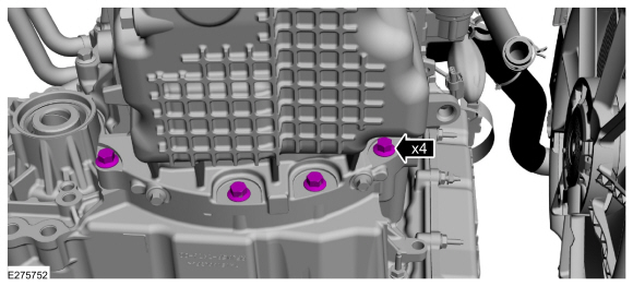
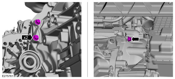
Remove the lower transmission-to-engine bolts.
-
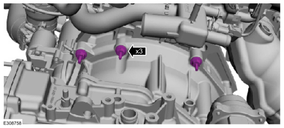
Remove the top transmission-to-engine bolts.
-
Remove the pin-type retainers and the fender panel.
-
Remove the bolt and the washer reservoir fill tube.
-
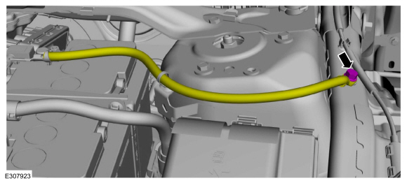
Disconnect the retainers and position aside the degas bottle hose.
-
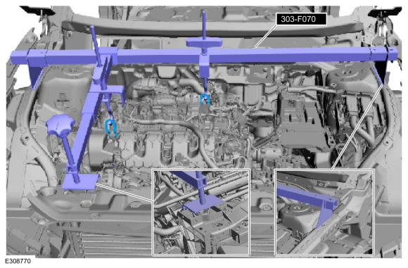
Using the special tools, support the engine.
Use Special Service Tool: 303-F070
Support Bar, Engine.
-
NOTE:
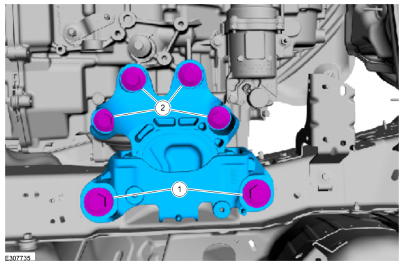
Remove the bolts in the following order to prevent damage to the transmission case.
-
Remove the transmission isolator to frame rail bolts.
-
Remove the transmission isolator to transmission bolts.
-
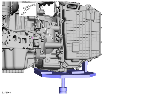
NOTICE:
Secure the transmission to the transmission jack with a safety strap.
NOTICE:
Make sure that no part of the wiring harness is trapped.
Support the transmission with a transmission jack.
Use the General Equipment: Transmission Jack
Use the General Equipment: Retaining Strap
-
Remove the RH and LH transmission-to-engine bolts.
-
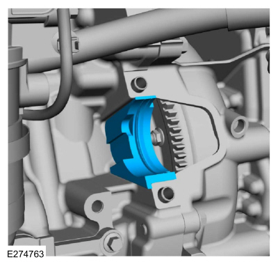
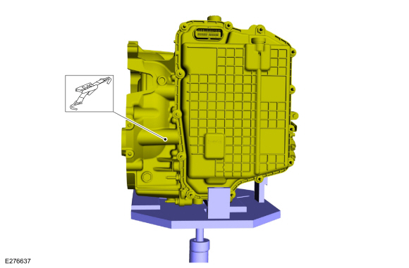
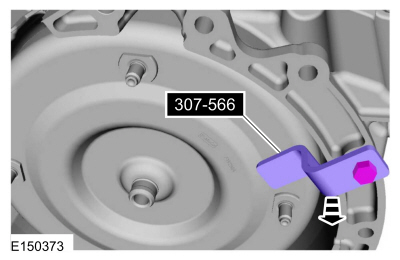
Slide the transmission back enough to install the
special tool and remove the transmission from the vehicle.
Use Special Service Tool: 307-566
Retainer, Torque Converter.
-
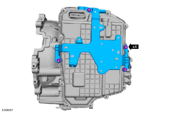
NOTE:
If transmission disassembly or installation of a
new transmission is necessary, remove the wire harness bracket.
Remove the nuts and the wire harness bracket.
-
NOTE:
If transmission disassembly or installation of a
new transmission is necessary, remove the transmission fluid cooler
tubes.
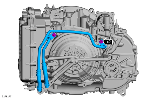
Remove the bolts and the transmission cooler tubes.
-
Inspect the transmission case to be sure that the
transmission fluid cooler tube seals and backing rings were removed with
the transmission fluid cooler tubes and are not stuck in the
transmission case. If the transmission fluid cooler tube seals or
backing rings are stuck in the transmission case, remove the seals and
backing rings.
Installation
All vehicles
-
NOTICE:
Failure to clean the transmission fluid cooler tubes can result in transmission failure.
If the transmission is to be overhauled or if
installing a new or re-manufactured transmission, carryout the
transmission fluid cooler backflushing and cleaning. Clean the
transmission-mounted transmission fluid cooler tubes by hand.
Refer to: Transmission Fluid Cooler - Backflushing and Cleaning
(307-02A Transmission Cooling - 8-Speed Automatic Transmission –
8F35/8F40, General Procedures).
-
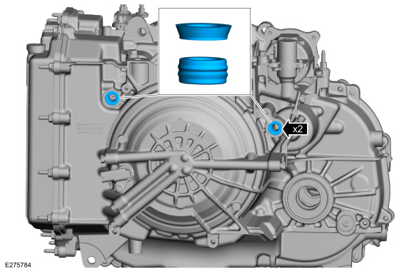
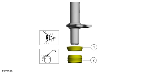
Inspect and lubricate the band seals and backing rings.
-
Band seal (7D285).
Material: Motorcraft® MERCON® ULV Automatic Transmission Fluid
/ XT-12-QULV
(WSS-M2C949-A, )
(MERCON® ULV)
-
Install the transmission cooler tubes and the bolts.
Torque:
97 lb.in (11 Nm)
-
NOTE:
If transmission disassembly or installation of a
new transmission is necessary, install the wire harness bracket.
Insatll the wire harness bracket and the nuts.
Torque:
80 lb.in (9 Nm)
-
NOTICE:
Secure the transmission to the transmission jack with a safety strap.
Using a transmission jack, support the transmission.
Use the General Equipment: Transmission Jack
Use the General Equipment: Retaining Strap
-
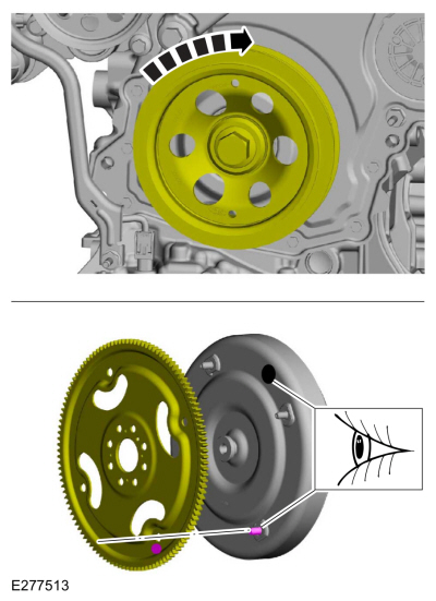
NOTICE:
The Balance mark on the torque converter must
be above the crankshaft centerline when the first torque converter nut
is tightened.
Position the balance mark (paint dot, sticker, or
laser etch) near the 12 O’clock position. Then rotate the converter to
position the nearest converter stud at the starter opening.
-
Install the special tool.
Use Special Service Tool: 307-566
Retainer, Torque Converter.
-
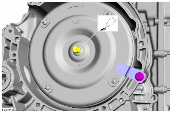
Lubricate the torque converter pilot hub with Multi-Purpose Grease.
Material: Motorcraft® Multi-Purpose Grease Spray
/ XL-5-A
(ESB-M1C93-B)
-
NOTICE:
The Balance mark on the torque converter must
be above the crankshaft centerline when the first torque converter nut
is tightened.
NOTE:
This step is only necessary if installing the original torque converter.
Rotate crankshaft clockwise to align the index marks made during removal.
-
NOTICE:
If the transmission is not positioned on the dowel pins, damage to the transmission may occur.
If the dowel pins were pulled out of the engine
block during removal, install new dowel pins in the engine block.
-
Position the transmission behind the engine and remove the special tool.
Use Special Service Tool: 307-566
Retainer, Torque Converter.
-
Position the transmission on the dowel pins and install the RH and LH transmission-to-engine bolts.
Torque:
35 lb.ft (48 Nm)
-
NOTE:
Install the bolts in the following order to prevent damage to the transmission case.
NOTE:
Install all bolts finger tight first, before applying torque.
NOTE:
Ensure bracket is seated on transmission case
before applying torque. May need to raise transmission first.
NOTE:
Ensure bracket on frame rail is seated on frame
rail before applying torque. May need to lower transmission first.
Install the transmission isolator and the bolts.
-
Tighten the transmission isolator to transmission bolts.
Torque:
129 lb.ft (175 Nm)
-
Tighten the transmission isolator to frame rail bolts.
Torque:
Stage 1:
103 lb.ft (140 Nm)
Stage 2:
120°
-
Position back the degas bottle hose and connect the retainers.
-
Install the washer reservoir fill tube and the bolt.
-
Install the fender panel and the pin-type retainers.
-
Install the top transmission-to-engine bolts.
Torque:
35 lb.ft (48 Nm)
-
Install the lower transmission-to-engine bolts.
Torque:
35 lb.ft (48 Nm)
-
Connect the coolant hose to the transmission.
-
Install the bracket, install the bolts and studbolt.
Torque:
129 lb.ft (175 Nm)
-
Position the wire harness and bracket, install the retainers.
Torque:
44 lb.in (5 Nm)
-
Install the transmission fluid warmer, the nuts and the bolt.
Torque:
133 lb.in (15 Nm)
-
Release the clamps and disconnect the transmission fluid cooler tubes from the transmission fluid warmer.
-
Connect the transmission fluid warmer coolant hoses and the clamps.
-
NOTE:
Only rotate the crankshaft in a clockwise direction.
Install the new torque converter nuts.
Torque:
35 lb.ft (48 Nm)
-
Install the stater motor isolator.
-
Install the stater motor.
Refer to: Starter Motor (303-06A Starting System - 2.0L EcoBoost (177kW/240PS) – MI4, Removal and Installation).
Refer to: Starter Motor (303-06B Starting System - 2.3L EcoBoost (199kW/270PS), Removal and Installation).
All wheel drive (AWD)
-
Install the Power Transfer Unit (PTU) 2.0 EcoBoost engine.
Refer to: Power Transfer Unit - Vehicles With: Power Transfer Unit
Oil-to-Coolant Cooler (307-07B Power Transfer Unit - 2.0L EcoBoost
(177kW/240PS) – MI4, Installation).
Refer to: Power Transfer Unit - Vehicles Without: Power Transfer Unit
Oil-to-Coolant Cooler (307-07B Power Transfer Unit - 2.0L EcoBoost
(177kW/240PS) – MI4, Installation).
-
Install the Power Transfer Unit (PTU) 2.3 EcoBoost engine.
Refer to: Power Transfer Unit - Vehicles With: Power Transfer Unit
Oil-to-Coolant Cooler (307-07C Power Transfer Unit - 2.3L EcoBoost
(199kW/270PS), Installation).
Refer to: Power Transfer Unit - Vehicles Without: Power Transfer Unit
Oil-to-Coolant Cooler (307-07C Power Transfer Unit - 2.3L EcoBoost
(199kW/270PS), Installation).
Vehicles with front wheel drive (FWD)
-
Install the bracket and the nuts.
Torque:
35 lb.ft (47 Nm)
-
-
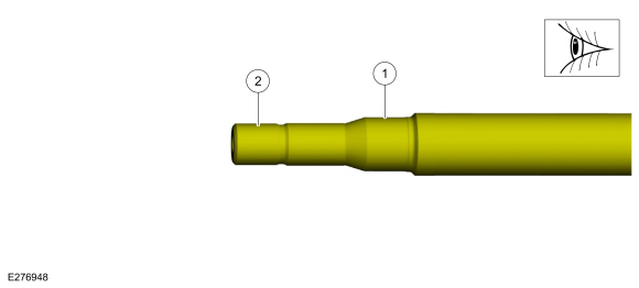
Inspect the RH halfshaft seal surface.
-
Inspect the differential side gear splines.
-
NOTE:
If the transmission has been replaced or overhauled, the halfshaft seals do not need to be replaced.
Install a new RH halfshaft seal.
Refer to: Halfshaft Seal RH (307-01A Automatic Transmission - 8-Speed
Automatic Transmission – 8F35/8F40, Removal and Installation).
-
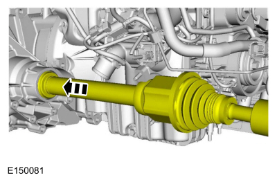
Install the RH halfshaft assembly.
-
Install the new halfshaft retaining strap and the new halfshaft retaining strap nuts.
Torque:
Stage 1:
44 lb.in (5 Nm)
Stage 2:
18 lb.ft (25 Nm)
Stage 3:
18 lb.ft (25 Nm)
-
Install the LH front halfshaft
Refer to: Front Halfshaft LH (205-04 Front Drive Halfshafts, Removal and Installation).
All vehicles
-
Uncover, clean and inspect all open ports.
-
Install the CAC pipe and retainers.
Torque:
80 lb.in (9 Nm)
-
Uncover, clean and inspect all open ports.
-
Connect the HO2S electrical connector and retainer.
-
Uncover, clean and inspect all open ports.
-
Install the CAC hose and the clamps.
Torque:
53 lb.in (6 Nm)
-
Connect the CAC pipe bypass valve electrical connector and wire retainers.
-
Install the radiator and heater hose and the clamps.
-
Position the radiator hose support and install the nut.
Torque:
80 lb.in (9 Nm)
-
Connect the TSS/ISSA TSS sensor electrical connector.
-
Position the wire harnesses and coolant hose, connect the retainers.
-
Connect the transmission connector.
-
Rotate the connector latch until it locks in place.
-
Slide the locking clip back to its original position.
-
Uncover, clean and inspect all open ports.
-
Install the CAC hose and clip.
-
Connect the CAC hose and install the clamp.
Torque:
53 lb.in (6 Nm)
-
Position the start/stop coolant pump and install the retainers.
Torque:
115 lb.in (13 Nm)
-
Connect the start/stop coolant pump electrical connector and install the wire harness retainer.
-
Position the wire harness and install the retainers.
Torque:
115 lb.in (13 Nm)
-
Install the manual park release lever and nut.
Torque:
106 lb.in (12 Nm)
-
-
Position back the manual park release cable and install the bolt.
Torque:
177 lb.in (20 Nm)
-
Connect the manual park release cable to the manual control lever.
-
Remove the hook and position back the coolant valve and hoses, install the nuts.
Torque:
106 lb.in (12 Nm)
-
Connect the start/stop accumulator solenoid connector.
-
Position the ground cable and install the bolt.
Torque:
26 lb.ft (35 Nm)
-
Install the LH cowl cover, the bolts and the pin-type retainer.
-
Install the RH cowl cover, the bolts and the pin-type retainer.
-
Install the following items:
-
Install the front sub frame.
Refer to: Front Subframe (502-00 Uni-Body, Subframe and Mounting System, Removal and Installation).
-
Install the cowl panel.
Refer to: Cowl Panel Grille (501-02 Front End Body Panels, Removal and Installation).
-
Install the air cleaner outlet pipe.
Refer to: Air Cleaner Outlet Pipe (303-12A Intake Air Distribution and
Filtering - 2.0L EcoBoost (177kW/240PS) – MI4, Removal and
Installation).
Refer to: Air Cleaner Outlet Pipe (303-12B Intake Air Distribution and
Filtering - 2.3L EcoBoost (199kW/270PS), Removal and Installation).
-
Install the battery tray.
Refer to: Battery Tray - 2.0L EcoBoost (177kW/240PS) – MI4/2.3L
EcoBoost (199kW/270PS) (414-01 Battery, Mounting and Cables, Removal and
Installation).
-
Fill the engine cooling system.
Refer to: Engine Cooling System Draining, Vacuum Filling and Bleeding
(303-03A Engine Cooling - 2.0L EcoBoost (177kW/240PS) – MI4, General
Procedures).
Refer to: Engine Cooling System Draining, Vacuum Filling and Bleeding
(303-03B Engine Cooling - 2.3L EcoBoost (199kW/270PS), General
Procedures).
-
Fill the transmission with transmission fluid.
Refer to: Transmission Fluid Drain and Refill (307-01A Automatic
Transmission - 8-Speed Automatic Transmission – 8F35/8F40, General
Procedures).
-
After completing the repairs, perform the Misfire
Monitor Neutral Profile Correction procedure using a diagnostic scan
tool.
-
If a new main control valve body is installed, the solenoid body strategy must be updated.
Refer to: Transmission Strategy Download (307-01A Automatic
Transmission - 8-Speed Automatic Transmission – 8F35/8F40, General
Procedures).
-
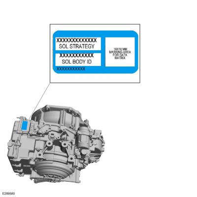
If a new main control valve body is installed, install a new solenoid body identification tag.
Removal
With the vehicle in NEUTRAL, position it on a hoist.
Refer to: Jacking and Lifting - Overview (100-02 Jacking and Lifting, Description and Operation)...
Removal
Remove the main control cover.
Refer to: Main Control Cover (307-01A Automatic Transmission - 8-Speed
Automatic Transmission – 8F35/8F40, Removal and Installation)...
Other information:
Special Tool(s) /
General Equipment
205-153
(T80T-4000-W)
Handle
307-758Installer, Axle Seal -FWD
Flat Headed Screw Driver
Removal
Remove the RH halfshaft.
Refer to: Front Halfshaft RH - AWD (205-04 Front Drive Halfshafts, Removal and Installation)...
Removal
NOTE:
Removal steps in this procedure may contain installation details.
Remove the rear seat cushion and cover as an assembly.
Refer to: Rear Seat Cushion Cover (501-10B Rear Seats, Removal and Installation).
Disconnect the power fold seat motor electrical connector...


 Removal and Installation - Turbine Shaft Speed (TSS) Sensor and Intermediate Speed Sensor A (ISSA)
 Removal and Installation - Transmission Internal Wiring Harness Frame