Lincoln Corsair: Automatic Transmission - 8-Speed Automatic Transmission – 8F35/8F40 / Removal and Installation - Main Control Valve Body
Removal
-
Remove the main control cover.
Refer to: Main Control Cover (307-01A Automatic Transmission - 8-Speed Automatic Transmission – 8F35/8F40, Removal and Installation).
Refer to: Main Control Cover (307-01A Automatic Transmission - 8-Speed Automatic Transmission – 8F35/8F40, Removal and Installation).
-
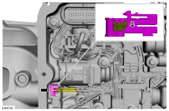
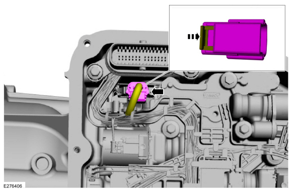
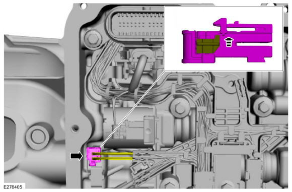
Unlock and disconnect the OSS sensor electrical connector.
 |
-
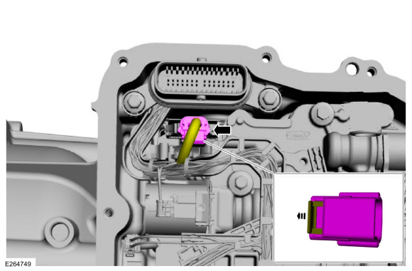
Unlock and disconnect the TR sensor electrical connector.
 |
-
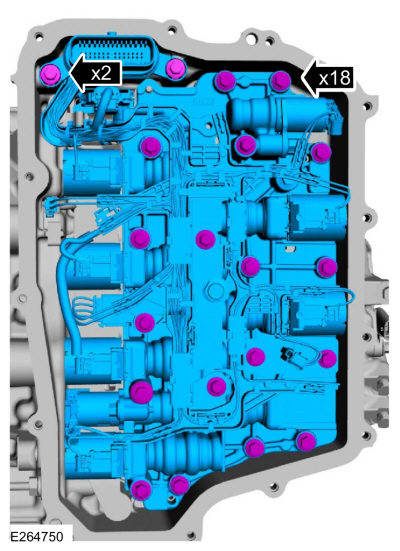
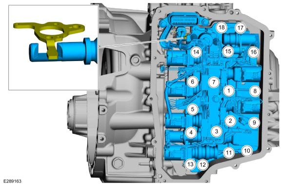
NOTE: Note the location of the short and long main control valve body bolts for assembly.
Remove the main control valve body bolts. Remove the main control valve body and transmission wiring harness assembly.
 |
Installation
-
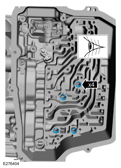
Verify the A (1, 2, 3, 4, 5), C (3, 7), F (2, 8), and
the D (SOWC) clutch main control valve body case seals are in place.
 |
-
NOTE: Note the location of the short and long main control valve body case bolts. Tighten the main control valve body bolts in the sequence shown.
NOTE: Verify the manual lever is positioned in the main control valve.
Install the main control, the transmission wiring harness and the main control bolts.
Torque:
Stage 1: 44 lb.in (5 Nm)
Stage 2: 62 lb.in (7 Nm)
 |
-
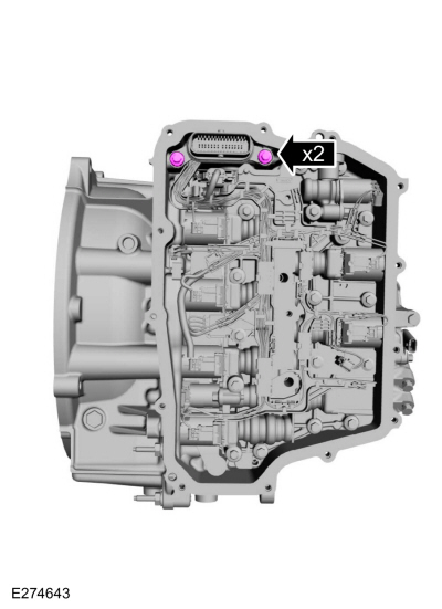
Install the wiring harness connector bolts.
Torque: 71 lb.in (8 Nm)
 |
-
Connect and lock he TR sensor electrical connector.
 |
-
Connect and lock the OSS sensor electrical connector.
 |
-
Install the main control cover.
Refer to: Main Control Cover (307-01A Automatic Transmission - 8-Speed Automatic Transmission – 8F35/8F40, Removal and Installation).
Refer to: Main Control Cover (307-01A Automatic Transmission - 8-Speed Automatic Transmission – 8F35/8F40, Removal and Installation).
-
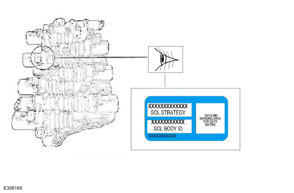
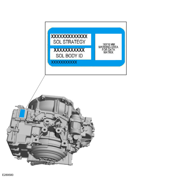
If a replacement transmission assembly is being installed or a new main
control valve body is installed, the PCM must be reflashed with a new
solenoid body strategy and identification data file.
Refer to: Transmission Strategy Download (307-01A Automatic Transmission - 8-Speed Automatic Transmission – 8F35/8F40, General Procedures).
-
NOTE: The 13-digit solenoid body strategy number displayed on the scan tool must match the solenoid body strategy number etched on the main control. If the numbers do not match, damage to the transmission or drivability concerns can occur.
NOTE: If the new main control was not supplied with a replacement solenoid strategy idenification tage, DO NOT INSTALL the main control as all required programming information is missing.
Verify the new main control software file solenoid strategy on the casting matches the new service solenoid body replacement tag.
 |
-
If a new main control valve body is installed, install a new solenoid body identification tag.
 |
 Removal and Installation - Main Control Cover
Removal
With the vehicle in NEUTRAL, position it on a hoist.
Refer to: Jacking and Lifting - Overview (100-02 Jacking and Lifting, Description and Operation)...
 Removal and Installation - Output Shaft Speed (OSS) Sensor
Materials
Name
Specification
Petroleum Jelly
-
Removal
Remove the main control valve body.
Remove the bolt and the fluid transfer pipe...
Other information:
Lincoln Corsair 2020-2026 Owners Manual: Tire Sealant and Inflator Kit (IF EQUIPPED)
Note: The temporary mobility kit contains enough sealant compound in the canister for one tire repair only. See your authorized Ford dealer for replacement sealant canisters. The kit is located under the load floor in the trunk. The kit consists of an air compressor to re-inflate the tire and a canister of sealing compound that will effectively seal most punctures caused by nails or simila..
Lincoln Corsair 2020-2026 Service Manual: Removal and Installation - Front Seat Cushion Blower Motor
Removal NOTE: Driver seat shown, passenger seat similar. Move the front seat to the full upward and forward position. Depower the SRS . Refer to: Supplemental Restraint System (SRS) Depowering (501-20B Supplemental Restraint System, General Procedures). Remove the front seat cushion blower motor. Disconnect the electrical connec..
Categories
- Manuals Home
- 1st Generation Lincoln Corsair Owners Manual
- 1st Generation Lincoln Corsair Service Manual
- Technical Specifications
- Programming the Garage Door Opener to Your Hand-Held Transmitter
- Selecting a Drive Mode. DRIVE MODES
- New on site
- Most important about car
360 Degree Camera Cameras
Locating the Rear View Camera

The rear view camera is on the tailgate.
Locating the Front View Camera