Lincoln Corsair: Automatic Transmission - 8-Speed Automatic Transmission – 8F35/8F40 / Removal and Installation - Main Control Cover
Removal
-
With the vehicle in NEUTRAL, position it on a hoist.
Refer to: Jacking and Lifting - Overview (100-02 Jacking and Lifting, Description and Operation).
-
Remove the air cleaner.
Refer to: Air Cleaner (303-12A Intake Air Distribution and Filtering -
2.0L EcoBoost (177kW/240PS) – MI4, Removal and Installation).
Refer to: Air Cleaner (303-12B Intake Air Distribution and Filtering - 2.3L EcoBoost (199kW/270PS), Removal and Installation).
-
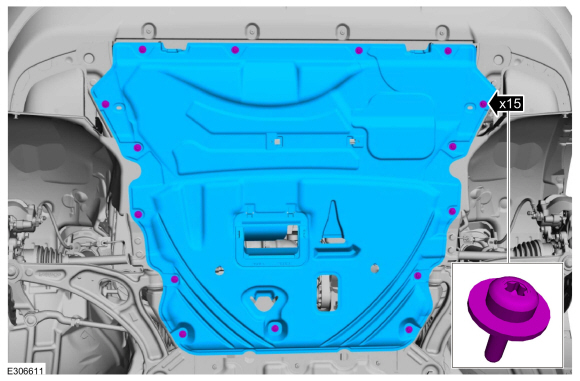
Remove the retainers and the underbody shield.
-
Remove the left front fender splash shield.
Refer to: Fender Splash Shield (501-02 Front End Body Panels, Removal and Installation).
-
Drain the transmission fluid.
Torque:
106 lb.in (12 Nm)
-
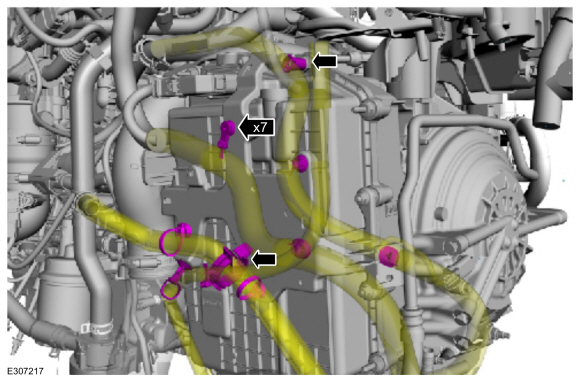
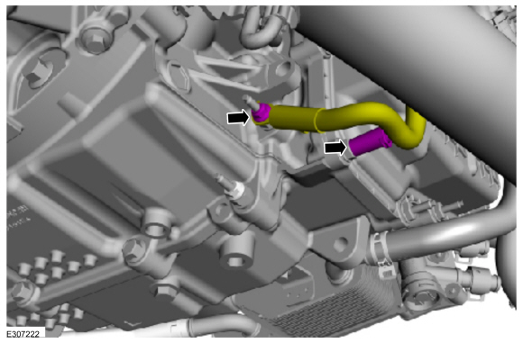
Remove the retainers and position aside the wiring harness and coolant hose.
-
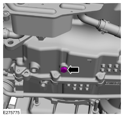
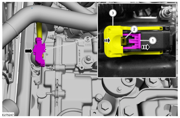
Disconnect transmission connector.
-
Slide the locking clip.
-
Press the tab.
-
While pressing the tab, rotate the connector latch.
-
Disconnect the retainer and the turbine shaft speed
sensor/intermediate speed sensor A (ISSA) electrical connector.
-
Remove the nut and wire harness retainer, position aside the ground cable.
-
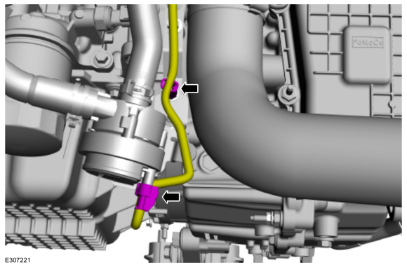
Remove the wire harness retainer and disconnect the start/stop coolant pump electrical connector.
-
Remove the nut and bolt, position aside the start/stop coolant pump.
-
Remove the charge air cooler intake pipe.
Refer to: Charge Air Cooler (CAC) Intake Pipe (303-12A Intake Air
Distribution and Filtering - 2.0L EcoBoost (177kW/240PS) – MI4, Removal
and Installation).
Refer to: Charge Air Cooler (CAC) Intake Pipe (303-12B Intake Air
Distribution and Filtering - 2.3L EcoBoost (199kW/270PS), Removal and
Installation).
-
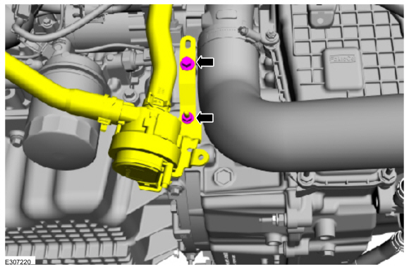
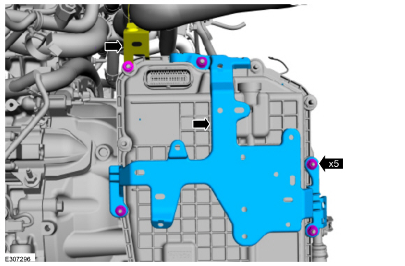
Remove the nuts and the wire harness bracket and position aside the radiator hose support.
-
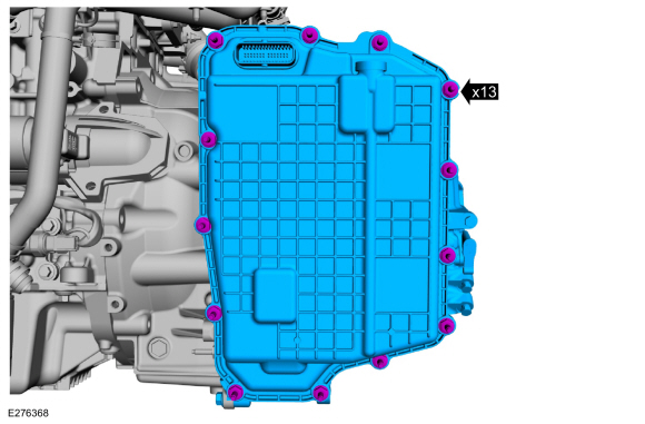
Remove the stud bolts and remove the main control cover.
Installation
-
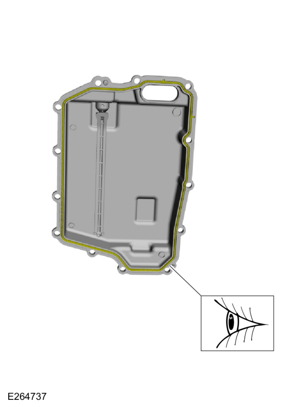
Inspect the main control cover seal for damage and install new if necessary.
-
Install the main control cover and the stud bolts.
Torque:
106 lb.in (12 Nm)
-
Position the radiator hose support and install the wire harness bracket, install the nuts.
Torque:
89 lb.in (10 Nm)
-
Install the charge air cooler intake pipe.
Refer to: Charge Air Cooler (CAC) Intake Pipe (303-12A Intake Air
Distribution and Filtering - 2.0L EcoBoost (177kW/240PS) – MI4, Removal
and Installation).
Refer to: Charge Air Cooler (CAC) Intake Pipe (303-12B Intake Air
Distribution and Filtering - 2.3L EcoBoost (199kW/270PS), Removal and
Installation).
-
Position back the start/stop coolant pump and install the nut and the bolt.
Torque:
80 lb.in (9 Nm)
-
Connect the start/stop coolant pump electrical connector and install the wire harness retainer.
-
Position the ground cable, install the nut and wire harness retainer.
Torque:
89 lb.in (10 Nm)
-
Disconnect the retainer and the turbine shaft speed
sensor/intermediate speed sensor A (ISSA) electrical connector.
-
Connect the transmission connector.
-
Rotate the connector latch until it locks in place.
-
Slide the locking clip back to its original position.
-
Position back the wiring harness and coolant hose, install the retainers.
-
Install the left front fender splash shield.
Refer to: Fender Splash Shield (501-02 Front End Body Panels, Removal and Installation).
-
Install the underbody shield and the retainers.
-
Install the air cleaner.
Refer to: Air Cleaner (303-12A Intake Air Distribution and Filtering -
2.0L EcoBoost (177kW/240PS) – MI4, Removal and Installation).
Refer to: Air Cleaner (303-12B Intake Air Distribution and Filtering - 2.3L EcoBoost (199kW/270PS), Removal and Installation).
-
Fill the transmission with transmission fluid.
Refer to: Transmission Fluid Drain and Refill (307-01A Automatic
Transmission - 8-Speed Automatic Transmission – 8F35/8F40, General
Procedures).
Special Tool(s) /
General Equipment
205-153
(T80T-4000-W)
Handle
307-758Installer, Axle Seal -FWD
307-759Installer, Axle Seal -AWD
Puller
Punch
Removal
Remove the power transfer unit...
Removal
Remove the main control cover.
Refer to: Main Control Cover (307-01A Automatic Transmission - 8-Speed
Automatic Transmission – 8F35/8F40, Removal and Installation)...
Other information:
Special Tool(s) /
General Equipment
303-F070Support Bar, EngineTKIT-1999A-F/LTTKIT-1999A-FM/FLM
Removal
With the vehicle in NEUTRAL, position it on a hoist.
Refer to: Jacking and Lifting - Overview (100-02 Jacking and Lifting, Description and Operation)...
Keyless Warning Alert
The horn will sound twice when you exit your
vehicle with the intelligent access key and
your vehicle is in RUN, indicating your vehicle
is still on.
Headlamps On Warning Chime
Sounds when you have left the headlamps
or parking lamps on and open the driver door
with the vehicle off...


 Removal and Installation - Halfshaft Seal RH - All-Wheel Drive (AWD)
 Removal and Installation - Main Control Valve Body