Lincoln Corsair: Front Disc Brake / Removal and Installation - Brake Pads
Materials
| Name | Specification |
|---|---|
| Motorcraft® Silicone Brake Caliper Grease and Dielectric Compound XG-3-A |
ESA-M1C200-A ESE-M1C171-A |
| Motorcraft® Metal Brake Parts Cleaner PM-4-A, PM-4-B, APM-4-C |
- |
Removal
 WARNING:
Service actions on vehicles equipped with electronic brake
booster and electronic parking brakes may cause unexpected brake
application, which could result in injury to hands or fingers. Put the
brake system into service mode prior to servicing or removing any brake
components. Failure to follow this instruction may result in serious
personal injury.
WARNING:
Service actions on vehicles equipped with electronic brake
booster and electronic parking brakes may cause unexpected brake
application, which could result in injury to hands or fingers. Put the
brake system into service mode prior to servicing or removing any brake
components. Failure to follow this instruction may result in serious
personal injury.
NOTE: Removal steps in this procedure may contain installation details.
-
Activate the brake service mode.
Refer to: Brake Service Mode Activation and Deactivation (206-00 Brake System - General Information, General Procedures).
-
Remove the wheel and tire.
Refer to: Wheel and Tire (204-04A Wheels and Tires, Removal and Installation).
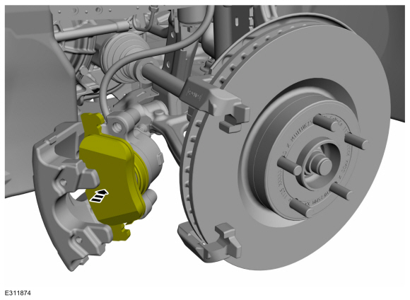
-
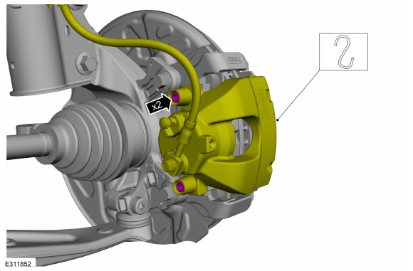
Remove the brake caliper spring.
 |
-
Remove the caps.
 |
-
NOTICE: Make sure that no load is placed on the brake hose.
NOTICE: Do not pry in the caliper sight hole to retract the pistons as this can damage the pistons and boots.
Remove the brake caliper guide pin bolts and position aside the brake caliper.
Torque: 21 lb.ft (28 Nm)
 |
Vehicles without adhesive on brake pad insulator
-
Remove the brake pads.
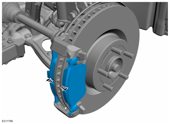 |
Vehicles with adhesive on brake pad insulator
-
NOTICE: Brake pads with adhesive on the insulator are one-time use only. When the brake pads are separated from the brake caliper, new brake pads must be installed to prevent brake noise and shudder.
NOTICE: When installing the new brake pads make sure to remove the foil backing from the outboard brake pads. Once the foil backing is removed from the brake pads do not touch the adhesive on the backing.
Separate the outboard brake pad from the brake caliper. Discard the brake pad.
 |
-
Remove the inboard brake pad.
 |
All vehicles
-
NOTICE: Protect the caliper pistons and boots when pushing the caliper piston into the caliper piston bores or damage to components may occur.
Use a C-clamp and a worn brake pad to compress the disc brake caliper pistons into the brake caliper bore.
 |
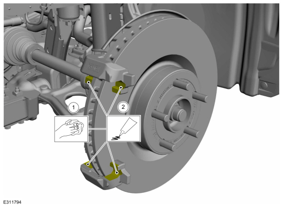
-
Apply the specified grease.
Material: Motorcraft® Silicone Brake Caliper Grease and Dielectric Compound / XG-3-A (ESA-M1C200-A) (ESE-M1C171-A)
 |
Installation
Vehicles with adhesive on brake pad insulator
NOTICE: Brake pads with adhesive on the insulator are one-time use only. When the brake pads are separated from the brake caliper, new brake pads must be installed to prevent brake noise and shudder.
NOTICE: When installing the new brake pads make sure to remove the foil backing from the outboard brake pads. Once the foil backing is removed from the brake pads do not touch the adhesive on the backing.
NOTE: A new brake caliper piston will have a protective cover. Make sure to remove the cover before installing the brake caliper.
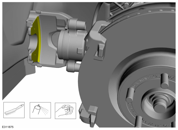
-
Clean all residual pad adhesive from the finger area
of the brake caliper. Make sure the finger area is free of grease and
foreign material.
Material: Motorcraft® Metal Brake Parts Cleaner / PM-4-A, PM-4-B, APM-4-C
 |
All vehicles
-
To install, reverse the removal procedure.
-
Deactivate the brake service mode.
Refer to: Brake Service Mode Activation and Deactivation (206-00 Brake System - General Information, General Procedures).
-
Apply the brake pedal several times to verify correct brake system operation.
Vehicles with adhesive on brake pad insulator
-
Start the engine and apply the brake pedal firmly 5
times to assure the outboard brake pads are bonded to the caliper.
 Removal and Installation - Brake Disc Shield
Removal
NOTE:
Removal steps in this procedure may contain installation details.
Remove the brake disc.
Refer to: Brake Disc (206-03 Front Disc Brake, Removal and Installation)...
 Removal and Installation - Front Brake Flexible Hose
Removal
WARNING:
Service actions on vehicles equipped with electronic brake
booster and electronic parking brakes may cause unexpected brake
application, which could result in injury to hands or fingers...
Other information:
Lincoln Corsair 2020-2026 Service Manual: Description and Operation - Body and Frame
The body consists of the following: Front bumper constructed of high-strength aluminum Rear bumper constructed of Boron ultra high-strength steel Front frame rails constructed of Dual Phase (DP) 600 high-strength steel Rear frame rails constructed of Boron ultra high-strength steel Fender reinforcement tube constructed of Dual Phase (DP) 800 high-strength steel ..
Lincoln Corsair 2020-2026 Service Manual: General Procedures - Power Door Window Initialization
Initialization WARNING: Before beginning any service procedure in this section, refer to Safety Warnings in section 100-00 General Information. Failure to follow this instruction may result in serious personal injury. Refer to: Health and Safety Precautions (100-00 General Information, Description and Operation). WARNING: Keep objects and body parts c..
Categories
- Manuals Home
- 1st Generation Lincoln Corsair Owners Manual
- 1st Generation Lincoln Corsair Service Manual
- Overhaul - Main Control Valve Body
- Technical Specifications
- Exterior Mirrors
- New on site
- Most important about car
Creating a Vehicle Wi-Fi Hotspot
You can create a Wi-Fi hotspot in your vehicle and allow devices to connect to it for access to the Internet.
 Select the settings option on
the
feature bar.
Select the settings option on
the
feature bar.