Lincoln Corsair: Engine System - General Information / General Procedures - Powertrain/Drivetrain Mount Neutralizing
Lincoln Corsair 2020-2026 Service Manual / Powertrain / Engine / Engine System - General Information / General Procedures - Powertrain/Drivetrain Mount Neutralizing
Adjustment
-
With the vehicle in NEUTRAL, position it on a hoist.
Refer to: Jacking and Lifting - Overview (100-02 Jacking and Lifting, Description and Operation).
-
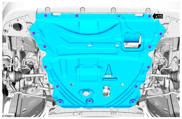
Remove the fasteners and the undershield.
 |
-
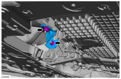
Remove the nuts and the bracket.
 |
-
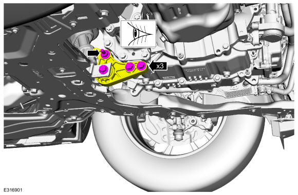
Loosen, but do not remove the roll restrictor fasteners. Verify that the roll restrictor is loose.
 |
-
-
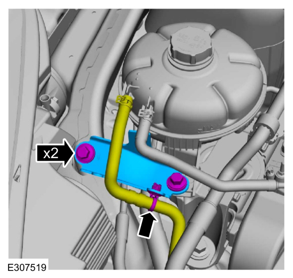
Detach the coolant hose retainer.
-
Remove the bolts and the degas bottle support bracket.
-
Detach the coolant hose retainer.
 |
-
Release the tabs and position the degas bottle aside.
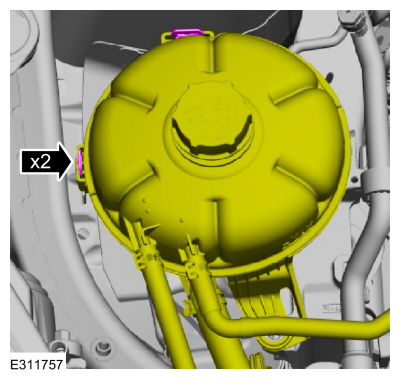 |
-
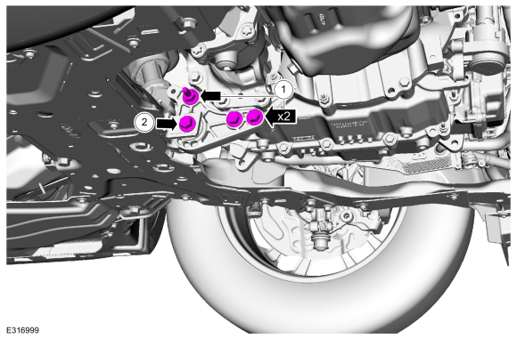
Loosen, but do not remove the engine mount bolts.
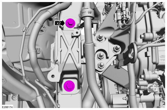 |
-
Loosen, but do not remove the transmission mount bolts.
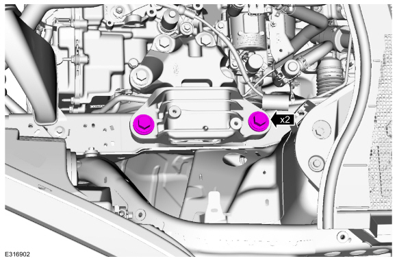 |
-
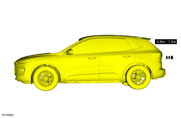
NOTE: Do not twist or strain the powertrain/drivetrain mounts or damage to the mounts may occur.
Start the vehicle and move it forward 0.6 m (1.97 ft) - 1.2 m (3.94 ft).
 |
-
NOTE: Do not twist or strain the powertrain/drivetrain mounts or damage to the mounts may occur.
Move the vehicle in reverse the same distance 0.6 m (1.97 ft) - 1.2 m (3.94 ft).
 |
-
Tighten the transmission mount bolts.
Torque:
Stage 1: 103 lb.ft (140 Nm)
Stage 2: 120°
|
-
Tighten the engine mount bolts.
Torque: 129 lb.ft (175 Nm)
|
-
Position the degas bottle on the tabs.
|
-
-
Install the degas bottle support bracket and the bolts.
-
Attach the coolant hose retainer.
-
Install the degas bottle support bracket and the bolts.
|
-
-
Tighten the bolts and studbolt.
Torque: 81 lb.ft (110 Nm)
-
Tighten the bolt.
Torque: 129 lb.ft (175 Nm)
-
Tighten the bolts and studbolt.
 |
-
Install the bracket and the nuts.
Torque: 35 lb.ft (47 Nm)
|
-
Install the undershield and fasteners.
|
-
Test the system for normal operation.
 General Procedures - Piston Selection
Check
NOTE:
Refer to the appropriate Section 303-01 for the specifications.
NOTE:
The cylinder bore must be within the specifications for taper and out-of-round before fitting a piston...
 General Procedures - RTV Sealing Surface Cleaning and Preparation
Special Tool(s) /
General Equipment
Plastic Scraper
Nylon Bristle Disk
Plastic Razor Blade
Lint-Free Towel
Isopropyl Alcohol – 90 Percent Minimum
Materials
Name
Specification
Motorcraft® Silicone Gasket RemoverZC-30-A, AZC-30-C
-
Motorcraft® Metal Surface Prep WipesZC-31-B
-
Motorcraft® Engine Shampoo and DegreaserZC-20, AZC-20..
Other information:
Lincoln Corsair 2020-2026 Owners Manual: Navigation (IF EQUIPPED)
Note: For more information, refer to our website. Select the navigation option on the feature bar. Map view menu. Zoom out. Zoom in. Route guidance menu. Destination entry menu. Setting a Destination Destination Entry Menu Setting a Destination Using the Text Entry Screen Text entry field. Automatic suggestions based on the text you enter. Information icon. Search. Keyboard s..
Lincoln Corsair 2020-2026 Service Manual: Removal and Installation - Rocker Panel Moulding
Special Tool(s) / General Equipment Interior Trim Remover Removal NOTE: Removal steps in this procedure may contain installation details. NOTE: LH side shown, RH side similar. Remove the rear quarter panel moulding. Refer to: Rear Quarter Panel Moulding (501-08 Exterior Trim and Ornamentation, Removal and Installation). Remove the push pins, the s..
Categories
- Manuals Home
- 1st Generation Lincoln Corsair Owners Manual
- 1st Generation Lincoln Corsair Service Manual
- Auto Hold (IF EQUIPPED)
- Technical Specifications
- Child Safety Locks
- New on site
- Most important about car
Keyless Starting
Note: The keyless starting system may not function if the key is close to metal objects or electronic devices such as cellular phones.
Note: A valid key must be located inside your vehicle to switch the ignition on and start the engine.
Ignition Modes

Copyright © 2026 www.licorsair.com