Lincoln Corsair: Engine - 2.0L EcoBoost (177kW/240PS) – MI4 / Assembly - Engine
Special Tool(s) /
General Equipment
 |
100-002
(TOOL-4201-C)
Holding Fixture with Dial Indicator Gauge |
 |
205-153
(T80T-4000-W)
Handle |
 |
303-096
(T74P-6150-A)
Installer, Camshaft Front Oil Seal
TKIT-2009TC-F |
 |
303-103
(T74P-6375-A)
Holding Tool, Flywheel
T74P-77000-A
TKIT-2009TC-F |
 |
303-1252
Stretchy Belt Remover/ Installer Tool
TKIT-2006UF-FLM
TKIT-2006UF-ROW |
 |
303-1521
Alignment Tool, Crankshaft Position Sensor
TKIT-2010C-FLM |
 |
303-1567
Sizer, Teflon Seal
TKIT-2010C-FLM |
 |
303-1685
Alignment Tool, Camshaft |
 |
303-1687
Installer, VCT Solenoid Seal |
 |
303-1688
Preload Tool, Balance Shaft |
 |
303-1689
Holding Tool, Crank Damper |
 |
303-328
(T88P-6701-B1)
Replacer, Rear Seal
TKIT-1988-FLM
TKIT-1988-F
TKIT-1988-LM |
 |
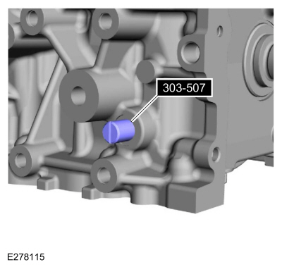
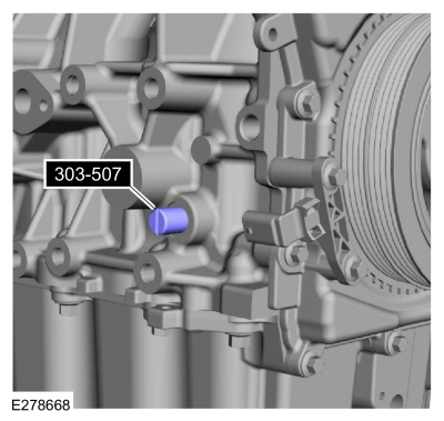
303-507
Timing Peg, Crankshaft TDC
TKIT-2001N-FLM
TKIT-2001N-ROW |
 |
310-205
Fuel Injector Brush |
 |
310-207
Installer, Fuel Injector Seal Assembly
TKIT-2009A-FLM |
| Feeler Gauge |
| Strap Wrench |
| Mounting Stand |
| Hose Clamp Remover/Installer |
| Piston Ring Compressor |
Materials
| Name |
Specification |
Motorcraft® High Performance Engine RTV Silicone
TA-357 |
WSE-M4G323-A6
|
NOTICE:
Do not loosen or remove the crankshaft pulley bolt without first
installing the special tools as instructed in this procedure. The
crankshaft pulley and the crankshaft timing sprocket are not keyed to
the crankshaft. The crankshaft, the crankshaft sprocket and the pulley
are fitted together by friction. For that reason, the crankshaft
sprocket is also unfastened if the pulley bolt is loosened. Before any
repair requiring loosening or removal of the crankshaft pulley bolt, the
crankshaft and camshafts must be locked in place by the special service
tools, otherwise severe engine damage can occur.
NOTICE:
During engine repair procedures, cleanliness is extremely
important. All parts must be thoroughly cleaned and any foreign
material, including any material created while cleaning gasket surfaces,
that enters the oil passages, coolant passages or the oil pan, can
cause engine failure.
-
Inspect the turbocharger or engine air intake system components and clean, if necessary.
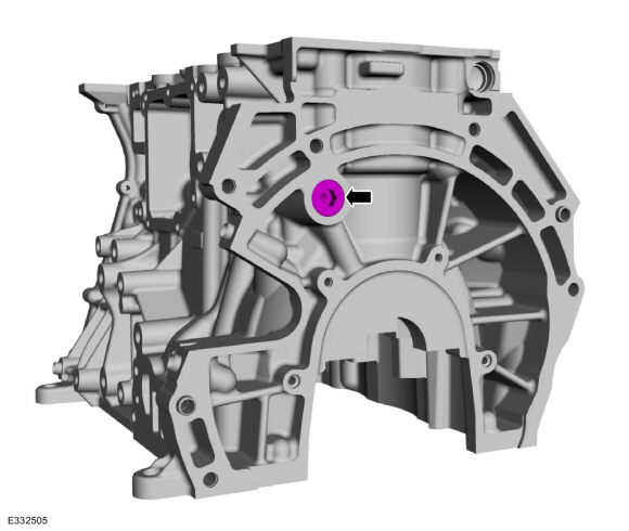
-
If necessary, install the new rear cylinder block plug.
Torque:
50 lb.ft (68 Nm)
-
If necessary, install the new front cylinder block plug.
Torque:
50 lb.ft (68 Nm)
-
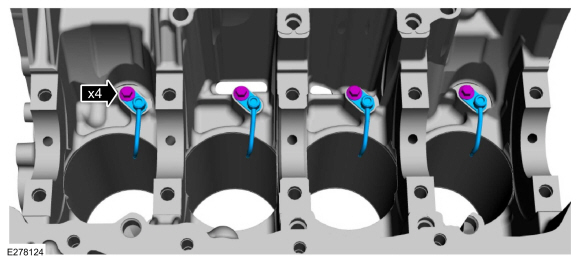
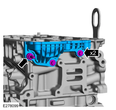
Install the engine piston oil cooler valves and the bolts.
Torque:
89 lb.in (10 Nm)
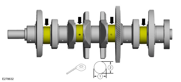
-
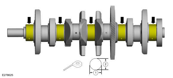
-
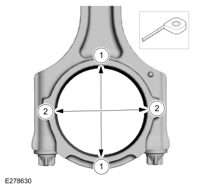
Measure the length or distance in two directions.
-
Record the smallest measurement for each crankshaft main bearing journal.
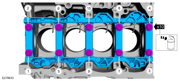
-
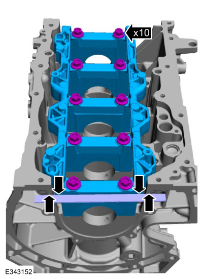
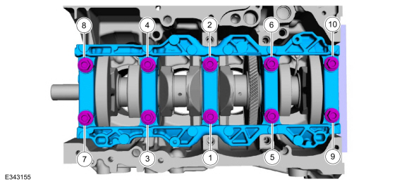
Using a straight edge, mounted flush and install the original main bearing beam bolts finger tight.
-
Using a straight edge, tighten the bolts in sequence shown.
Torque:
Stage 1:
44 lb.in (5 Nm)
Stage 2:
18 lb.ft (25 Nm)
Stage 3:
90°
-
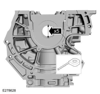
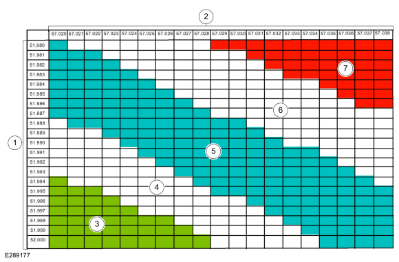
Measure each crankshaft block main bearing bore diameter.
-
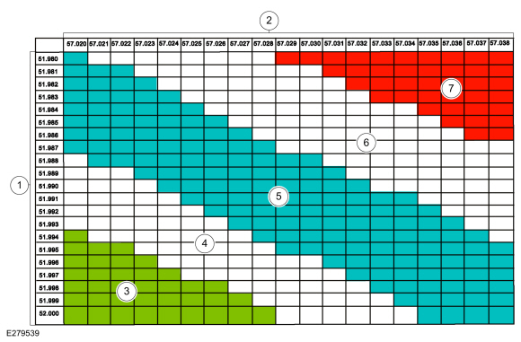
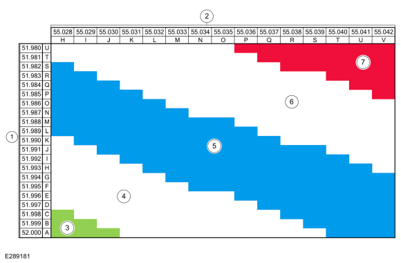
NOTE:
This chart is for main bearings number 1, 2, 4 and 5.
NOTE:
The bearing color corresponds to the number marked on the bearing.
Using the chart, select the correct grade connecting rod bearings.
-
Crankshaft journal diameter
-
Cylinder block bore diameter
-
Upper Bearing Green: 1 / Lower Bearing Green: 1
-
Upper Bearing Blue: 2/ Lower Bearing Green: 1
-
Upper Bearing Blue: 2 / Lower Bearing Blue: 2
-
Upper Bearing Red: 3/ Lower Bearing Blue: 2
-
Upper Bearing Red: 3 / Lower Bearing Red: 3
-
NOTE:
This chart is for main bearing number 3.
-
Crankshaft journal diameter
-
Cylinder block bore diameter
-
Green: Upper Bearing Blue: 2/ Lower Bearing Green: 1
-
White: Upper Bearing Brown: 4/ Lower Bearing Green: 1
-
Blue: Upper Bearing Brown: 4/ Lower Bearing Blue: 2
-
Yellow: Upper Bearing Brown: 4/ Lower Bearing Red: 3
-
Red: Upper Bearing Black: 6/ Lower Bearing Red: 3
-
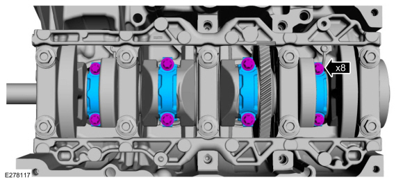
Using the original bolts, install the connecting rod caps.
Torque:
Stage 1:
177 lb.in (20 Nm)
Stage 2:
30 lb.ft (40 Nm)
Stage 3:
90°
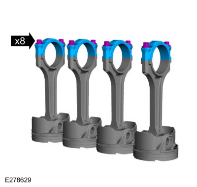
-
-
Measure the length or distance in two directions.
-
Record the smallest measurement for each connecting rod.
-
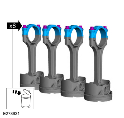
-
Remove the bolts and the connecting rod caps.
-
-
Measure the length or distance in two directions.
-
Record the smallest measurement for each connecting rod journal.
-
NOTE:
The bearing color corresponds to the number marked on the bearing.
Using the chart, select the correct grade connecting rod bearings.
-
Crankshaft journal diameter
-
Connecting rod diameter
-
Upper Bearing Green: 1 / Lower Bearing Green: 1
-
Upper Bearing Blue: 2/ Lower Bearing Green: 1
-
Upper Bearing Blue: 2 / Lower Bearing Blue: 2
-
Upper Bearing Red: 3/ Lower Bearing Blue: 2
-
Upper Bearing Red: 3 / Lower Bearing Red: 3
-
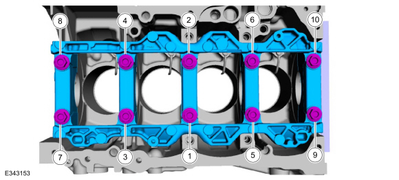
-
Remove the bolts in sequence shown and discard.
-
Remove the main bearing beam.
-
NOTE:
Before assembling the cylinder block, all sealing
surfaces must be free of chips, dirt, paint and foreign material. Also,
make sure the coolant and oil passages are clear.
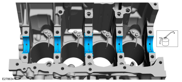
NOTE:
If reusing the crankshaft main bearings, install them in
their original positions and orientation as noted during disassembly.
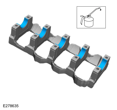
Lubricate with clean engine oil and install the crankshaft main bearings.
-
NOTE:
If reusing the crankshaft main bearings, install them in
their original positions and orientation as noted during disassembly.
Lubricate with clean engine oil and install the main bearing beam bearings.
-
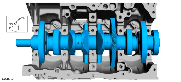
Lubricate with clean engine oil and install the crankshaft.
-
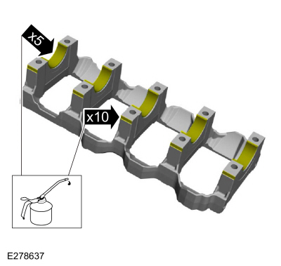
Lubricate with clean engine oil.
-
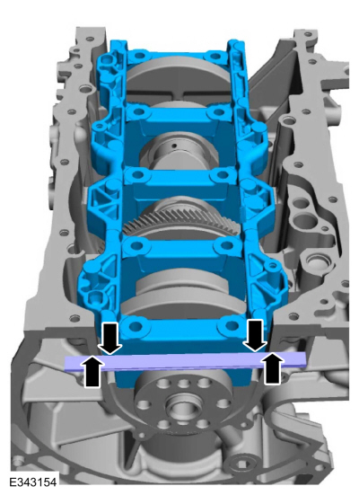
Using a straight edge, install the main bearing beam flush.
-
NOTE:
Lubricate the new main bearing beam bolts threads and under the bolt heads with clean engine oil.
NOTE:
Position the crankshaft to the rear of the cylinder
block, then position the crankshaft to the front of the cylinder block
before tightening the main bearing beam bolts.
Using a straight edge, install the bolts and tighten in sequence shown.
Torque:
Stage 1:
44 lb.in (5 Nm)
Stage 2:
18 lb.ft (25 Nm)
Stage 3:
90°
-
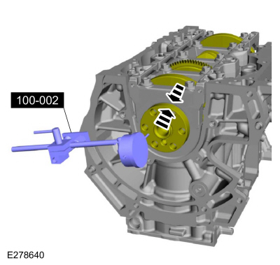
-
Position the crankshaft to the rear of the cylinder block.
-
Zero the Dial Indicator Gauge with Holding Fixture.
Use Special Service Tool: 100-002
(TOOL-4201-C)
Holding Fixture with Dial Indicator Gauge.
-
Move the crankshaft to the front of the cylinder block. Note and record the crankshaft end play.
-
Acceptable crankshaft end play is 0.220-0.450 mm
(0.0087-0.0177 in). If the crankshaft end play exceeds the specified
range, install new parts as necessary.
-
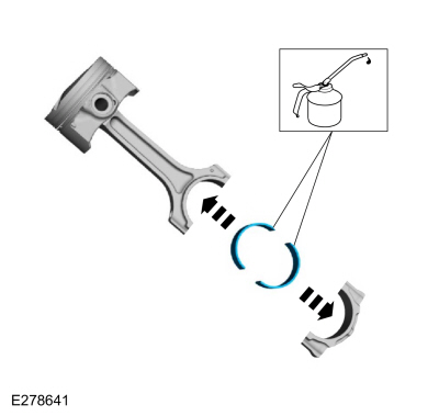
NOTE:
If reusing the connecting rod bearings, install them in
their original positions and orientation as noted during disassembly.
Lubricate with clean engine oil and install the connecting rod bearings.
-
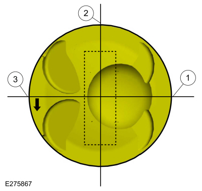
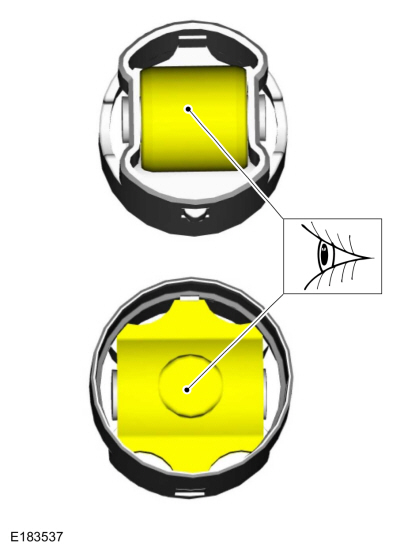
NOTE:
Align the piston rings on the piston.
NOTE:
Arrow indicates front of engine.
-
Upper oil control segment ring gap location.
-
Oil control spacer gap location.
-
Lower oil control segment ring gap location.
-
NOTICE:
Be sure not to scratch the cylinder wall or crankshaft
journal with the connecting rod. Push the piston down until the
connecting rod bearing seats on the crankshaft journal.
NOTE:
Make sure the piston arrow on top is facing toward the front of the engine.
Lubricate with clean engine oil. Using a piston ring compressor, install the pistons.
Use the General Equipment: Piston Ring Compressor
-
NOTICE:
The rod cap installation must keep the same orientation as marked during disassembly or engine damage may occur.
NOTE:
After installation of each connecting rod cap, rotate the crankshaft to verify smooth operation.
Install the connecting rod caps, bolts and tighten in 3 stages.
Torque:
Stage 1:
177 lb.in (20 Nm)
Stage 2:
30 lb.ft (40 Nm)
Stage 3:
90°
-
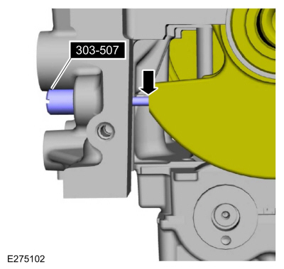
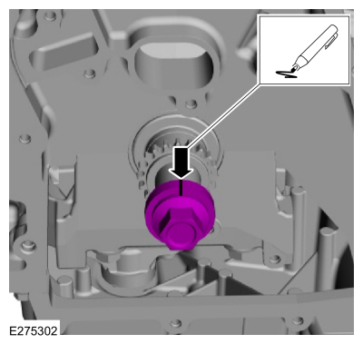
-
Install Special Service Tool: 303-507
Timing Peg, Crankshaft TDC.
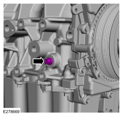
-
Rotate the crankshaft slowly clockwise until the
crankshaft balance weight is up against the special tool. The engine is
now at TDC .
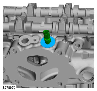
-
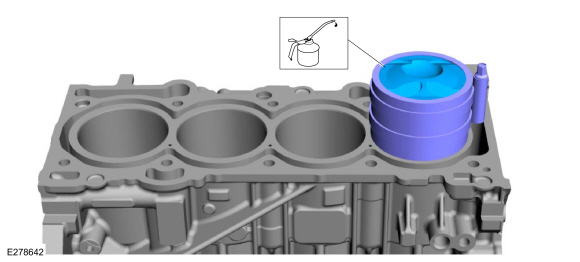
Prime the oil pump. Add 2 tablespoons of clean engine oil to the oil pump and rotate the oil pump by hand.
-
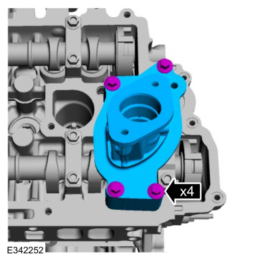
NOTE:
Due to the precision interior construction of the balancer unit, it should not be disassembled.
NOTE:
The original adjustment shims must be installed in their original positions.
NOTE:
Confirm by visual inspection that there is no damage to
the balancer unit gear and verify that the shaft turns smoothly. If
there is any damage or malfunction, replace the balancer unit.
Install the adjustment shims in their original positions on
the seat faces of the balancer unit. With the balancer unit shaft marks
in the TDC position, slowly
install the balancer unit to the cylinder block to avoid interference
between the crankshaft drive gear and the balancer unit driven gear.
-
Install the bolts and tighten in 2 stages.
Torque:
Stage 1:
133 lb.in (15 Nm)
Stage 2:
45°
-
Remove Special Service Tool: 303-507
Timing Peg, Crankshaft TDC.
-
Install the crankshaft bolt and rotate the crankshaft to
confirm that there are no meshing problems between the balancer unit
gear and the crankshaft gear.
-
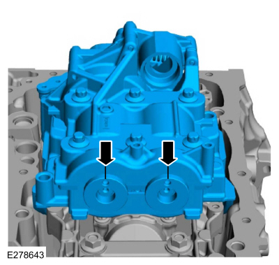
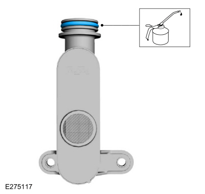
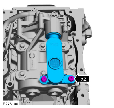
Lubricate the oil screen and pickup tube O-ring seal with clean engine oil.
-
Install the oil pickup and screen and the bolts.
Torque:
97 lb.in (11 Nm)
-
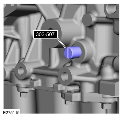
-
Install Special Service Tool: 303-507
Timing Peg, Crankshaft TDC.
-
Rotate the crankshaft slowly clockwise until the
crankshaft balance weight is up against the special tool. The engine is
now at TDC .
-
Remove Special Service Tool: 303-507
Timing Peg, Crankshaft TDC.
 |
|
-
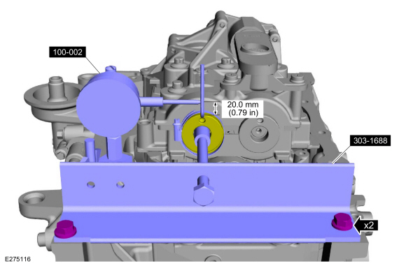
NOTE:
Measure the backlash and verify that it is within
specified range at all of the following 6 positions: 10 degrees, 30
degrees, 100 degrees, 190 degrees, 210 degrees and 280 degrees. It will
be necessary to reset the measuring equipment between measurements.
NOTE:
The measurement must be taken with the Dial Indicator
Gauge with Holding Fixture, a 5-mm Allen wrench and worm clamp set up as
shown.
-
Mark the Allen wrench with a file 20 mm (0.79 in) above the driven gear top surface.
-
Install the balance shaft preload tool and bolts as shown.
Use Special Service Tool: 303-1688
Preload Tool, Balance Shaft.
-
Install and position the dial indicator gauge with holding fixture on the Allen wrench 20 mm (0.79 in) as shown.
Use Special Service Tool: 100-002
(TOOL-4201-C)
Holding Fixture with Dial Indicator Gauge.
-
Rotate the crankshaft clockwise and measure the backlash
at all of the following 6 positions: 10 degrees, 30 degrees, 100
degrees, 190 degrees, 210 degrees and 280 degrees.
-
Backlash specifications are 0.040 to 0.140 mm (0.00157 to 0.0055 in).
-
If the backlash exceeds the specified range, carry out the Balance Shaft Backlash procedure.
Refer to: Balance Shaft Backlash (303-01B Engine - 2.3L EcoBoost (199kW/270PS), General Procedures).
 |
|
-
-
Install Special Service Tool: 303-507
Timing Peg, Crankshaft TDC.
-
Rotate the crankshaft slowly clockwise until the
crankshaft balance weight is up against the special tool. The engine is
now at TDC and must remain at the TDC position until the timing drive components and crankshaft pulley are installed.
-
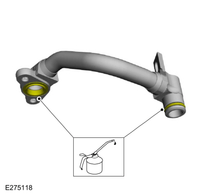
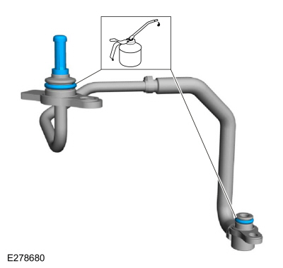
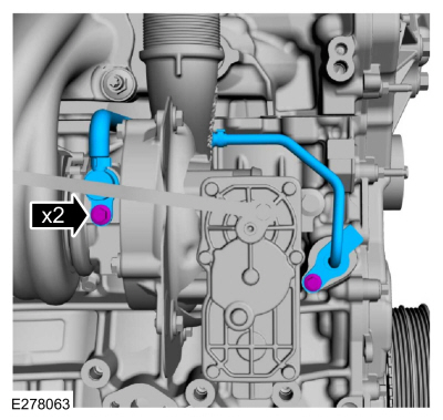
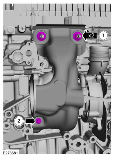
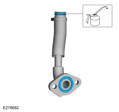
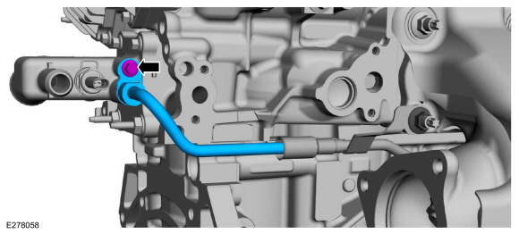
Lubricate the oil inlet tube O-ring seals with clean engine oil.
-
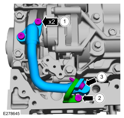
-
Install the oil inlet tube and the bolts.
Torque:
97 lb.in (11 Nm)
-
Install the oil inlet tube bracket and the bolt.
Torque:
97 lb.in (11 Nm)
-
Install the oil inlet tube-to-bracket bolt.
Torque:
97 lb.in (11 Nm)
-
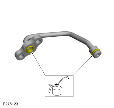
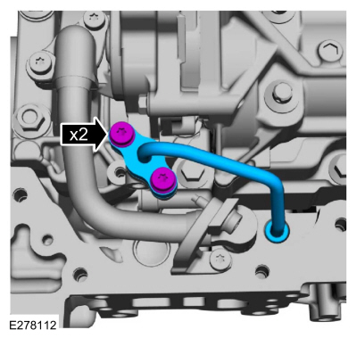
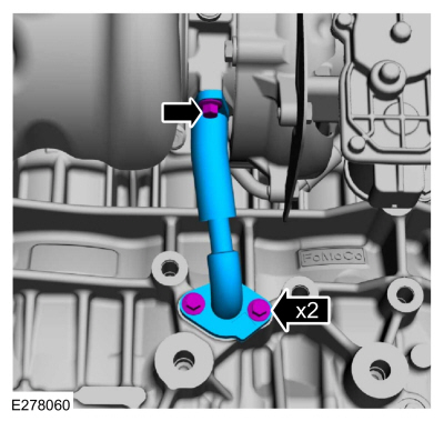
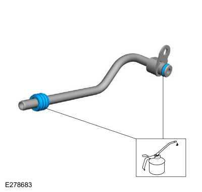
Lubricate the oil outlet tube O-ring seals with clean engine oil.
-
Install the oil outlet tube and the bolts.
Torque:
97 lb.in (11 Nm)
-
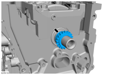
Install the crankshaft sprocket.
-
-
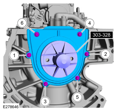
Using the special tool, position the crankshaft rear oil seal onto the crankshaft.
Use Special Service Tool: 303-328
(T88P-6701-B1)
Replacer, Rear Seal.
-
Install the bolts and tighten in sequence shown.
Torque:
97 lb.in (11 Nm)
-
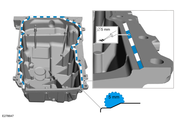
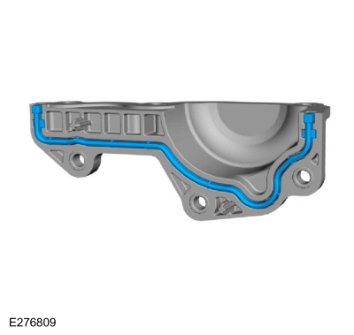
NOTE:
If the oil pan is not secured within 10 minutes of
silicone sealant application, the silicone sealant must be removed and
the sealing area cleaned. Allow to dry until there is no sign of
wetness, or 10 minutes, whichever is longer. Failure to follow this
procedure can cause future oil leakage.
Apply a 5 mm bead of silicone sealant on the chamfer, as shown.
Material: Motorcraft® High Performance Engine RTV Silicone
/ TA-357
(WSE-M4G323-A6)
-
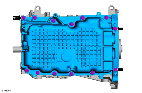
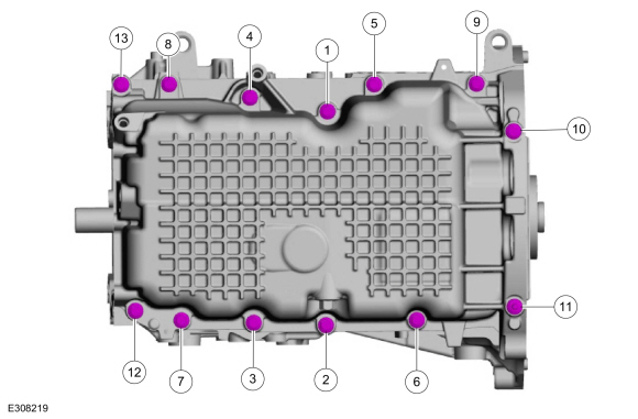
Install the oil pan and the new bolts finger tight.
-
Tighten the bolts in sequence shown.
Torque:
18 lb.ft (25 Nm)
-
Install the wiring harness retainer stud bolts.
Torque:
22 lb.ft (30 Nm)
-
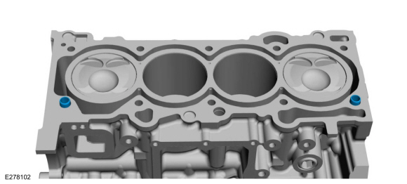
Install the cylinder block bushings.
-
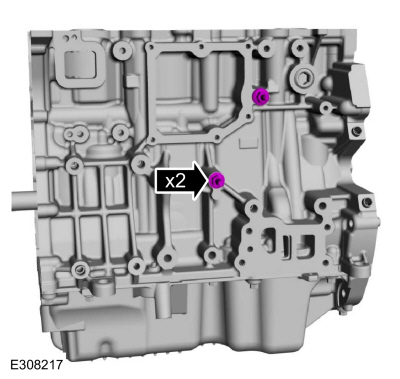
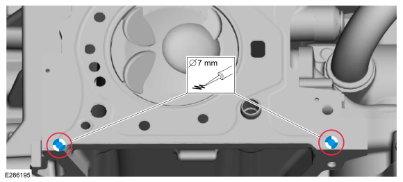
NOTICE:
Do not allow silicone sealant in or near the
high-pressure oil feed hole. Any restriction in the high-pressure oil
feed may result in engine damage.
NOTE:
The cylinder head must be installed within 10 minutes of applying the sealant.
Apply a 7 mm (0.28 in) drop of silicone sealant at positions shown on the cylinder block.
Material: Motorcraft® High Performance Engine RTV Silicone
/ TA-357
(WSE-M4G323-A6)
-
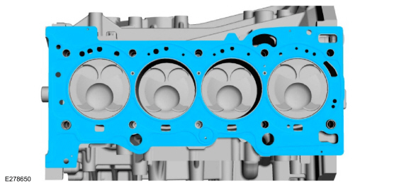
Install a new cylinder head gasket.
-
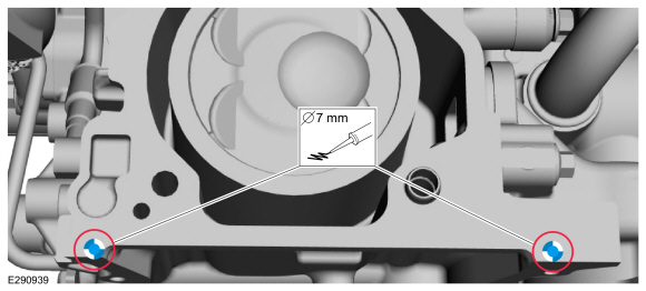
NOTICE:
Do not allow silicone sealant in or near the
high-pressure oil feed hole. Any restriction in the high-pressure oil
feed may result in engine damage.
NOTE:
The cylinder head must be installed within 10 minutes of applying the sealant.
Apply a 7 mm (0.28 in) drop of silicone sealant at positions shown.
Material: Motorcraft® High Performance Engine RTV Silicone
/ TA-357
(WSE-M4G323-A6)
-
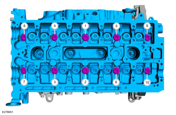
NOTE:
The cylinder head bolts are torque-to-yield and must not be reused. New cylinder head bolts must be installed.
Install the cylinder head and bolts and tighten in sequence shown in 5 stages.
Torque:
Stage 1:
62 lb.in (7 Nm)
Stage 2:
133 lb.in (15 Nm)
Stage 3:
41 lb.ft (55 Nm)
Stage 4:
90°
Stage 5:
90°
-
Install a new cylinder head cover gasket.
-
Install the cylinder head cover, bolts and stud bolt.
Torque:
97 lb.in (11 Nm)
-
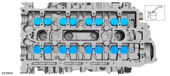
Lubricate with clean engine oil and install the valve tappets in their original position.
-
NOTICE:
If any new parts are being installed (cylinder head,
valves, tappets, camshafts) it is necessary to check the valve
clearance, follow the next 15 steps exactly or serious damage to the
engine may occur. If the original parts are being installed it is not
necessary to check the valve clearance so proceed to step 68.
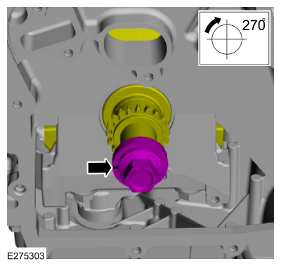
Install the crankshaft bolt and place a paint mark on the crankshaft bolt at the 12 o'clock position.
-
-
Remove Special Service Tool: 303-507
Timing Peg, Crankshaft TDC.
-
NOTE:
Rotating the crankshaft will position all of the pistons
below the deck of the cylinder block and allow the camshafts to be
installed and the valve clearance checked without the possibility of
damage to the valves or pistons.
Using the crankshaft bolt and washer, rotate the crankshaft
clockwise 270 degrees until the paint mark is at the 9 o'clock position.
-
NOTICE:
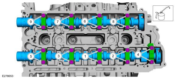
Failure to follow the camshaft tightening procedure can result in damage to the camshafts.
NOTE:
Lubricate the camshaft journals and camshaft bearing caps with clean engine oil.
-
Lubricate the camshafts and caps with clean engine oil and install the camshafts, caps and bolts.
-
Tighten 2 turns at a time in the sequence shown in 2 stages.
Torque:
Stage 1:
62 lb.in (7 Nm)
Stage 2:
142 lb.in (16 Nm)
-
Lubricate the camshaft journals with clean engine oil and install the front camshaft bearing cap and bolts.
Torque:
Stage 1:
62 lb.in (7 Nm)
Stage 2:
142 lb.in (16 Nm)
-
NOTICE:
Do not remove the spark plugs when the engine is hot or
cold soaked. Spark plug thread or cylinder head damage can occur. Make
sure the engine is warm (hand touch after cooling down) prior to spark
plug removal.
NOTICE:
If a spark plug is dropped, internal damage may result
and the spark plug must be discarded. The use of a damaged spark plug
may cause cylinder misfire resulting in engine damage.
NOTE:
Only use hand tool to remove the spark plugs.
Remove the spark plugs.
-
-
Using the flats of the camshaft, rotate the camshaft to
place the cam lobe at base circle, with the lobe pointed away from the
tappet.
-
Use a feeler gauge to measure the clearance of each valve and record its location.
Use the General Equipment: Feeler Gauge
-
Repeat to measure all of the lobe/tappet clearances.
-
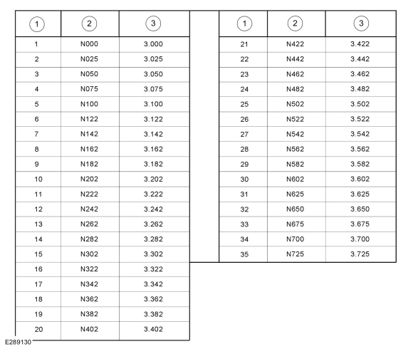
Valve tappet assembly grade chart
-
Grade
-
Id Mark
-
Thickness (mm)
-
NOTE:
There are two numbers on the valve tappet, one is date code and the other is valve tappet thickness.
NOTE:
The date code “R0605” represents the year made (R), the month (06) and the day (05).
NOTE:
A tappet with the number N650 has the thickness of 3.650 mm.
NOTE:
Select tappets using this formula: tappet thickness =
measured clearance + the existing tappet thickness - nominal clearance.
NOTE:
The nominal clearance is:
-
intake: 0.25 mm (0.0095 in).
-
exhaust: 0.36 mm (0.0142 in).
NOTE:
The acceptable clearances after being fully installed are:
-
intake: 0.19-0.31 mm (0.0075-0.0122 in).
-
exhaust: 0.3-0.42 mm (0.0118-0.0165 in).
Select the closest tappet size to the ideal tappet thickness available and mark the installation location.
-
NOTE:
Only use hand tool to install the spark plugs.
Install the spark plugs.
Torque:
106 lb.in (12 Nm)
-
Remove the bolts and the front camshaft bearing cap.
-
NOTICE:
Failure to follow the camshaft loosening procedure can result in damage to the camshafts.
NOTE:
Note the location and orientation of each camshaft
bearing cap and the position of the camshaft lobes on the No. 1 cylinder
for installation reference.
Loosen the camshaft bearing caps in sequence 2 turns at a
time until all tension is released from the camshaft bearing caps.
Remove the bolts, caps and camshafts.
-
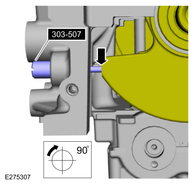
Install Special Service Tool: 303-507
Timing Peg, Crankshaft TDC.
-
NOTE:
Rotating the crankshaft will position the engine at TDC and allow you
to install the camshafts in the same position as noted during the
disassembly.
Rotate the crankshaft clockwise 90 degrees so the crankshaft contacts the special tool.
-
If necessary, replace any tappets with the correct tappets
selected during the valve clearance check and lubricate with clean
engine oil.
-
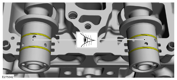
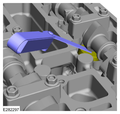
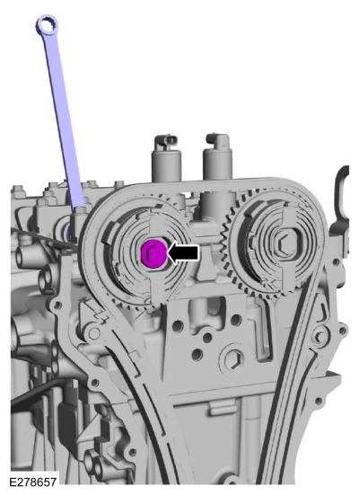
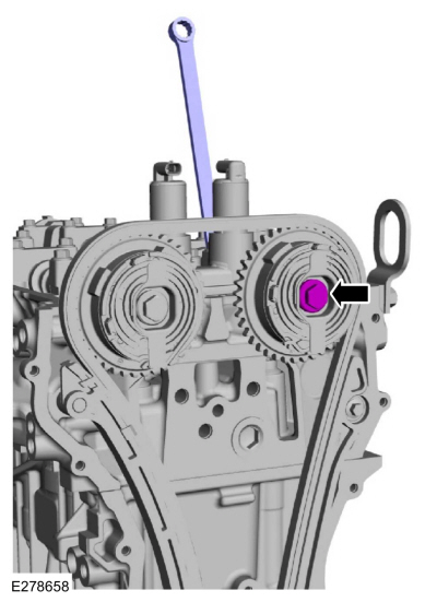
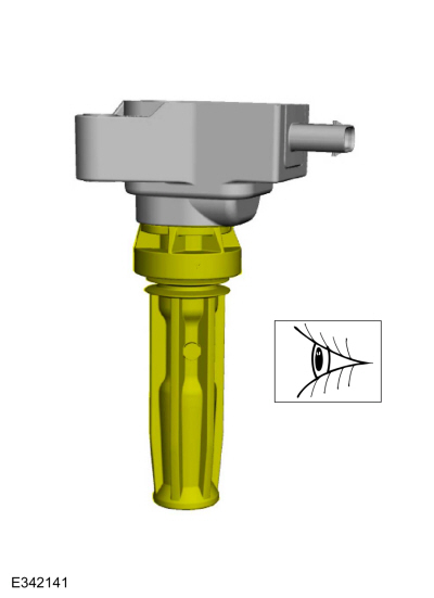
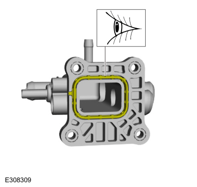
NOTICE:
The camshaft seal gaps must be at the 12 o'clock position or damage to the engine may occur.
Inspect and position the camshaft seals gaps at the 12 o'clock position as shown.
 |
|
-
NOTICE:
Install the camshafts with the alignment slots in the
camshafts lined up so the Camshaft Alignment Plate can be installed
without rotating the camshafts. Make sure the lobes on the No. 1
cylinder are in the same position as noted in the removal procedure.
Rotating the camshafts when the timing chain is removed, or installing
the camshafts 180 degrees out of position can cause severe damage to the
valves and pistons.
NOTICE:
Failure to follow the camshaft tightening procedure can result in damage to the camshafts.
NOTE:
Lubricate the camshaft journals and camshaft bearing caps with clean engine oil.
-
Lubricate with clean engine oil and install the camshafts, caps and bolts.
-
Tighten the camshaft bearing cap bolts one turn at a time, until finger-tight.
-
Tighten 2 turns at a time in the sequence shown in 2 stages.
Torque:
Stage 1:
62 lb.in (7 Nm)
Stage 2:
142 lb.in (16 Nm)
 |
|
-
-
Lubricate the camshaft journals with clean engine oil.
-
Install the front camshaft bearing cap and the bolts and tighten in 2 stages.
Torque:
Stage 1:
62 lb.in (7 Nm)
Stage 2:
142 lb.in (16 Nm)
-
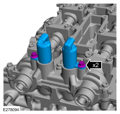
Install the VCT oil control solenoids and the bolts.
Torque:
97 lb.in (11 Nm)
-
NOTICE:
The special tool is for camshaft alignment only. Using
this tool to prevent engine rotation can result in engine damage.
Install Special Service Tool: 303-1685
Alignment Tool, Camshaft.
-
NOTE:
Do not tighten the VCT unit bolts at this time.
-
Install the VCT units and the new bolts finger-tight.
-
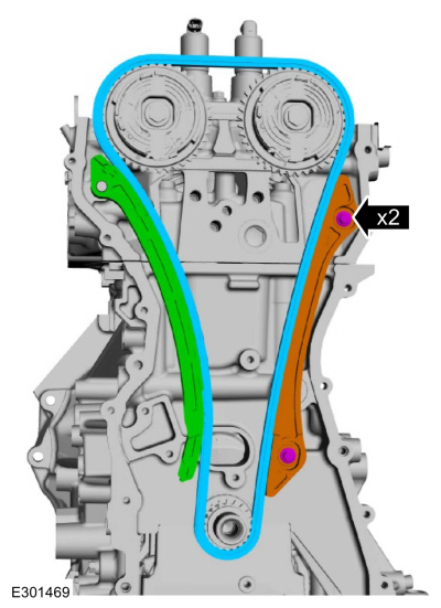
Install the tensioner arm, timing chain, timing chain guide and the bolts.
Torque:
97 lb.in (11 Nm)
NOTE:
If the timing chain tensioner plunger is not pinned in the compressed position, follow the next step.
-
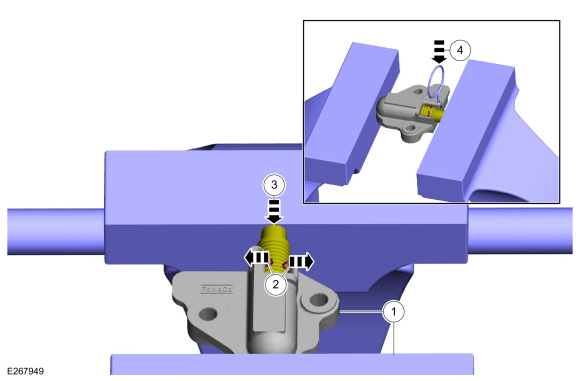
Reset the timing chain tensioner.
-
Position the timing chain tensioner in a soft-jawed vise.
-
Spread the ends of the ratchet wire clip apart.
-
Using the soft-jawed vise, compress the plunger to the reset position.
-
Install a locking pin in the 2 holes of the timing chain tensioner body to hold the plunger in place.
-
NOTE:
Do not remove the locking pin until the tensioner bolts are tightened.
-
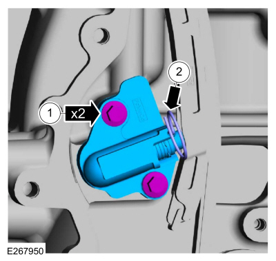
Install the timing chain tensioner and the bolts.
Torque:
89 lb.in (10 Nm)
-
Remove the locking pin.
-
NOTICE:
Use an open-ended wrench to prevent the component from turning.
Tighten the exhaust VCT unit bolt in 2 stages.
Torque:
Stage 1:
26 lb.ft (35 Nm)
Stage 2:
135°
-
NOTICE:
Use an open-ended wrench to prevent the component from turning.
Tighten the intake VCT unit bolt in 2 stages.
Torque:
Stage 1:
26 lb.ft (35 Nm)
Stage 2:
135°
-
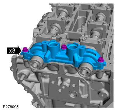
NOTE:
The engine front cover must be secured within 10 minutes
of Silicone Gasket and Sealant application. If the engine front cover
is not secured within 10 minutes, the sealant must be removed and the
sealing area cleaned.
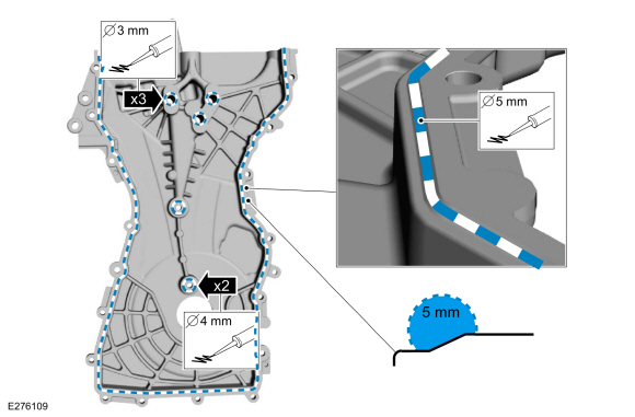
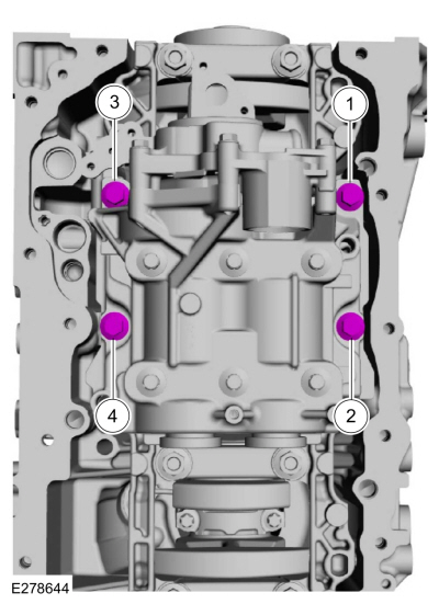
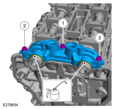
-
Apply a 3 mm (0.12 in) bead of silicone sealant on the 3 upper bosses, as shown.
Material: Motorcraft® High Performance Engine RTV Silicone
/ TA-357
(WSE-M4G323-A6)
-
Apply a 4 mm (0.16 in) bead of silicone sealant on the chamfer on the 2 lower bosses, as shown.
Material: Motorcraft® High Performance Engine RTV Silicone
/ TA-357
(WSE-M4G323-A6)
-
Apply a 5 mm (0.19 in) bead of silicone sealant on the chamfer, as shown.
Material: Motorcraft® High Performance Engine RTV Silicone
/ TA-357
(WSE-M4G323-A6)
 |
|
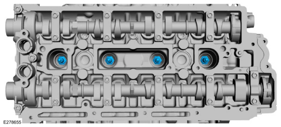
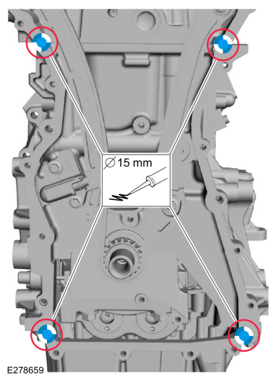
-
NOTE:
The engine front cover must be secured within 10 minutes
of Silicone Gasket and Sealant application. If the engine front cover
is not secured within 10 minutes, the sealant must be removed and the
sealing area cleaned.
Apply a 15 mm (0.59 in) drop of silicone sealant at the
cylinder head-to-cylinder block and cylinder block-to-oil pan joint
areas.
Material: Motorcraft® High Performance Engine RTV Silicone
/ TA-357
(WSE-M4G323-A6)
-
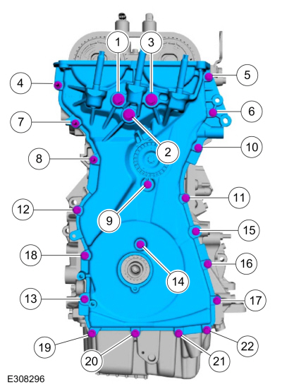
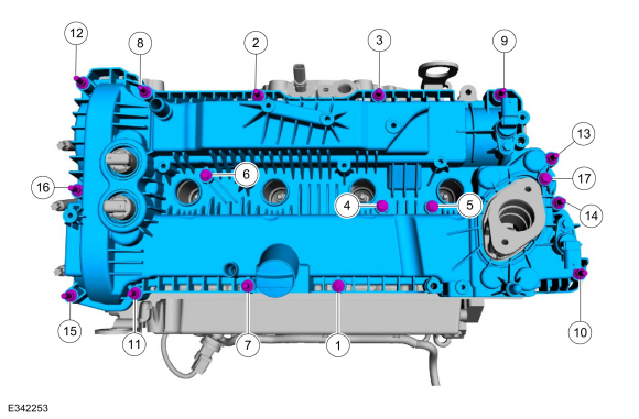
Install the engine front cover and the fasteners and tighten in the sequence shown.
Torque:
Bolts 1 - 3:
35 lb.ft (48 Nm)
Bolts 4 - 22:
97 lb.in (11 Nm)
-
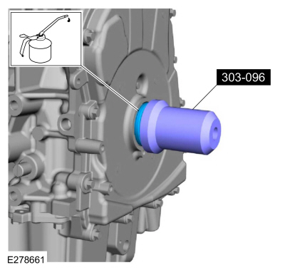
NOTE:
Remove the through-bolt from the Camshaft Front Oil Seal Installer.
Lubricate with clean engine oil and using the special tool, install the crankshaft front seal.
Use Special Service Tool: 303-096
(T74P-6150-A)
Installer, Camshaft Front Oil Seal.
-
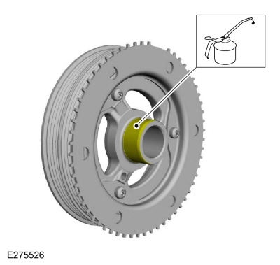
Lubricate the crankshaft pulley with clean engine oil.
-
Install the crankshaft pulley as shown.
-
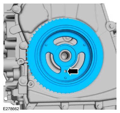
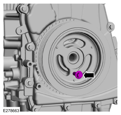
NOTE:
This step will correctly align the crankshaft pulley to the crankshaft.
Install an M6 bolt.
-
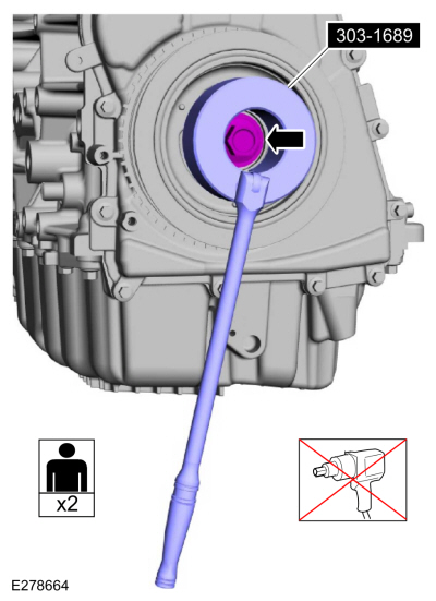
NOTICE:
The crankshaft must remain in the TDC
position during installation of the pulley bolt or damage to the
engine can occur. Therefore, the crankshaft pulley must be held in place
with the crank damper holding tool and the bolt should be installed
using hand tools only.
Using the special tool and breaker bar, tighten the crankshaft pulley.
Use Special Service Tool: 303-1689
Holding Tool, Crank Damper.
Use the General Equipment: Strap Wrench
Torque:
Stage 1:
74 lb.ft (100 Nm)
Stage 2:
90°
-
Remove the M6 bolt.
-
NOTE:
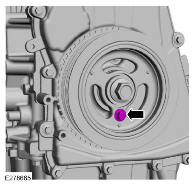
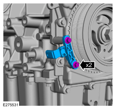
Do not tighten the CKP sensor bolts at this time.
Install the CKP sensor and the bolts finger-tight.
-
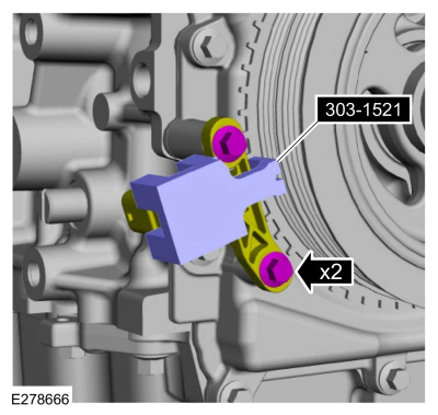
Install the Special Tool onto the CKP sensor and the tooth of the crankshaft pulley trigger wheel.
Use Special Service Tool: 303-1521
Alignment Tool, Crankshaft Position Sensor.
Torque:
97 lb.in (11 Nm)
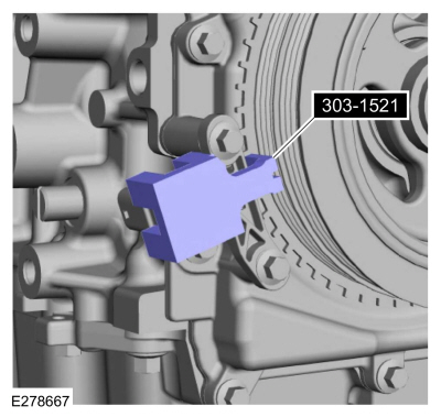
-
Remove Special Service Tool: 303-1521
Alignment Tool, Crankshaft Position Sensor.
-
Remove Special Service Tool: 303-507
Timing Peg, Crankshaft TDC.
-
Install the engine plug bolt.
Torque:
177 lb.in (20 Nm)
-
Remove Special Service Tool: 303-1685
Alignment Tool, Camshaft.
-
Install the high-pressure fuel pump drive unit and the bolts.
Torque:
97 lb.in (11 Nm)
-
-
Install the exhaust manifold heat shield on the new CHT sensor.
-
Install the CHT sensor.
Torque:
97 lb.in (11 Nm)
-
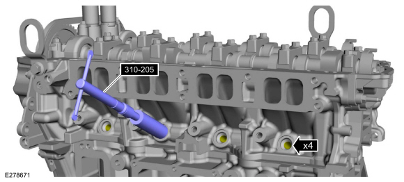
NOTICE:
Do not use compressed air or the Fuel Injector Brush to
clean the tip of the fuel injectors. Failure to follow this instruction
may result in damage to the fuel injectors.
NOTE:
Make sure to thoroughly clean any residual fuel or
foreign material from the cylinder head, block and the general
surrounding area of the fuel rails and injectors.
Using the special tool, clean the fuel injector bores.
Use Special Service Tool: 310-205
Fuel Injector Brush.
 |
|
-
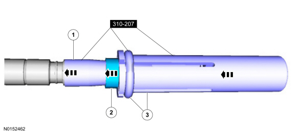
NOTICE:
Do not lubricate the new lower Teflon® fuel injector seals.
-
Install the Teflon® Seal Guide onto the fuel injector tip.
Install Special Service Tool: 310-207
Installer, Fuel Injector Seal Assembly.
-
NOTICE:
Once the Teflon® seal is installed on the Teflon®
Seal Guide, it should immediately be installed onto the fuel injector to
avoid excessive expansion of the Teflon® seal.
NOTE:
Make sure that new lower fuel injector Teflon® seals are installed.
Install the new Teflon® seals onto the Teflon® Seal
Guide, using the Pusher Tool, slide the Teflon® seals along the Teflon®
Seal Guide
-
Using the Pusher Tool, slide the Teflon® seals off of
the Teflon® Seal Guide and into the groove on the fuel injectors.
-
Remove the special tool.
Use Special Service Tool: 310-207
Installer, Fuel Injector Seal Assembly.
 |
|
-
NOTE:
Make sure the Teflon® seal is fully seated in the groove on the fuel injector before sizing the Teflon® seal.
-
Massage and warm the Teflon® seal with your fingers
before the Teflon® seal sizer tool is installed. This will aid in
installing the Teflon® seal sizer tool.
-
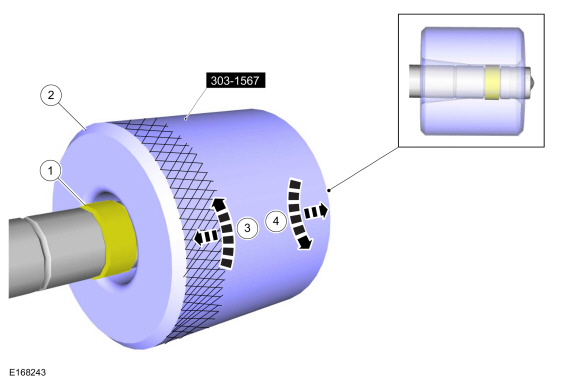
NOTE:
The beveled opening of the Teflon® seal sizer tool goes away from the seal.
Position the Teflon® seal sizer tool with the larger
opening towards the Teflon® seal. Push while turning the Teflon® seal
sizer tool 180 degrees.
Use Special Service Tool: 303-1567
Sizer, Teflon Seal.
-
Once the Teflon® seal sizer tool is installed, check and
make sure the Teflon® seal is in the sizing portion of the Teflon® seal
sizer tool. After one minute, turn the Teflon® seal sizer tool back 180
degrees and remove.
-
After one minute, turn the Teflon® seal sizer tool back 180 degrees and remove.
 |
|
-
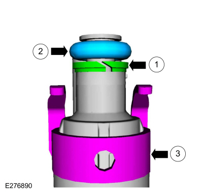
NOTICE:
The new the fuel injector support rings must be
installed in the correct orientation with the wide surface area facing
up against the fuel injector O-ring seals. Improperly installed support
rings may cause the fuel system to leak.
NOTE:
Make sure that new fuel injector support rings and new fuel injector O-ring seals are installed.
-
Install the new the fuel injector support rings.
-
NOTE:
Do not lubricate the new lower Teflon® fuel injector seals.
Install the new fuel injector O-rings.
-
Install the new the fuel injector clips.
-
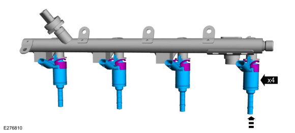
NOTICE:
The FRP sensor must be replaced if it is removed from the fuel rail.
NOTE:
The anti-rotation finger of the fuel injector clip must slip into the groove of the fuel rail cup.
Install the fuel injectors in the fuel rail.
-
NOTE:
Do not lubricate the new lower Teflon® fuel injector seals.
NOTE:
Make sure that new fuel rail bolts are installed.
-
Install the fuel rail by push down on the fuel rail above the injectors.
-
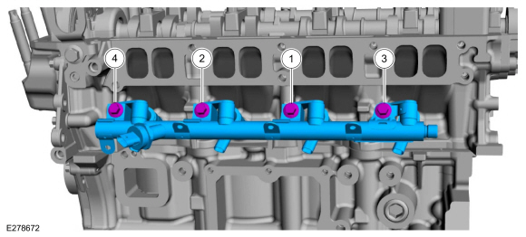
Install the bolts and tighten in sequence shown in 5 stages.
Torque:
Stage 1:
Tighten to:
89 lb.in (10 Nm)
Stage 2:
Back off to:
0 lb.in (0 Nm)
Stage 3:
Wait 5 seconds:
0 turn(s)
Stage 4:
Tighten to:
124 lb.in (14 Nm)
Stage 5:
Tighten an additional:
30°
-
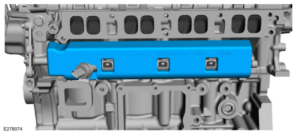
Install the fuel rail insulator.
-
-
Install the harness and attach the fuel rail wiring harness retainers.
-
Connect the fuel rail wiring harness electrical connectors.
-
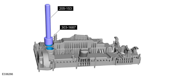
NOTE:
Installation of new seals is only required if damaged seals were removed during disassembly of the engine.
If removed, using the special tools, install the VCT seals.
Use Special Service Tool: 205-153
(T80T-4000-W)
Handle.
, 303-1687
Installer, VCT Solenoid Seal.
-
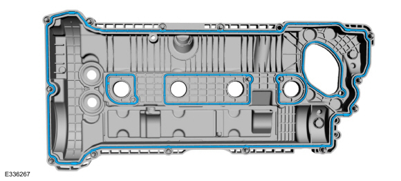
Install new valve cover gaskets.
-
Apply a 5.5 mm bead of silicone sealant.
Material: Motorcraft® High Performance Engine RTV Silicone
/ TA-357
(WSE-M4G323-A6)
-
NOTE:
The valve cover must be secured within 10 minutes of
silicone gasket application. If the valve cover is not secured within 10
minutes, the silicone sealant must be removed and the sealing area
cleaned.
Install the valve cover and tighten the fasteners in the sequence shown.
Torque:
97 lb.in (11 Nm)
-
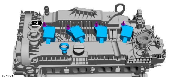
Inspect and replace any ignition coil-on-plug rubber boots with cracks, rips or tears.
-
-
Install the ignition coil-on-plugs and the fasteners.
Torque:
97 lb.in (11 Nm)
-
Install the oil level indicator.
-
Install the fuel tube bracket and the nut.
Torque:
80 lb.in (9 Nm)
-
Inspect and replace if damaged.
-
Install the coolant outlet, stud bolt and the bolts.
Torque:
97 lb.in (11 Nm)
-
Install the CAC pipe bracket and the nuts.
Torque:
44 lb.in (5 Nm)
-
-
If removed, install the studs.
Torque:
159 lb.in (18 Nm)
-
Install a coolant outlet tube seal and lubricate with clean engine coolant.
-
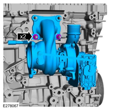
Install the turbocharger and the nuts finger tight.
-
Install the coolant outlet tube O-ring seal and lubricate with clean engine oil.
-
Install the coolant outlet tube and the bolt.
Torque:
35 lb.ft (48 Nm)
-
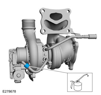
Install the oil supply filter and O-ring seals and lubricate the O-ring seals with clean engine oil.
-
NOTICE:
The oil supply pipe must be seated prior to fastener rundown or damage to the oil supply pipe may occur.
Install the new cylinder block-to-turbocharger oil supply pipe and the bolts.
Torque:
97 lb.in (11 Nm)
-
Tighten the turbocharger nuts.
Torque:
39 lb.ft (53 Nm)
-
Install the heat shield, nuts and the bolt finger-tight.
-
-
Tighten the nuts.
Torque:
39 lb.ft (53 Nm)
-
Tighten the bolt.
Torque:
97 lb.in (11 Nm)
-
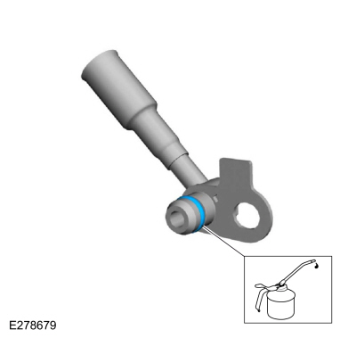
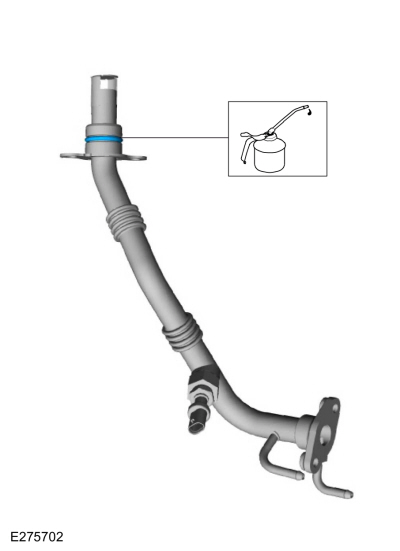
Lubricate the O-ring seal with clean engine oil.
-
NOTE:
The oil drain hose must be fully seated prior to fastener rundown.
Install the new .turbocharger-to-cylinder block oil return pipe and the bolts.
Torque:
97 lb.in (11 Nm)
-
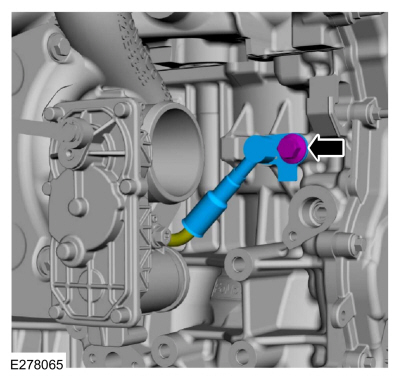
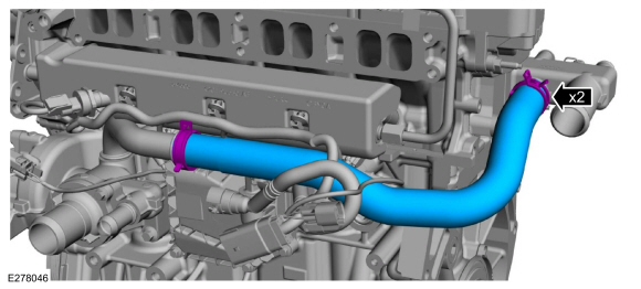
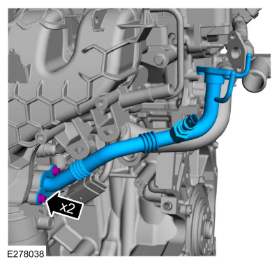
Install the turbocharger coolant inlet tube seals and lubricate with clean engine oil.
-
Install the turbocharger coolant inlet tube and the bolt.
Torque:
97 lb.in (11 Nm)
-
Install coolant hose bracket and the bolt.
Torque:
97 lb.in (11 Nm)
-
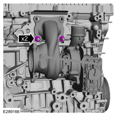
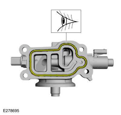
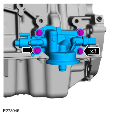
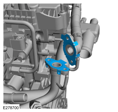
Install a new coolant pump adapter assembly gasket.
-
Install the coolant pump adapter assembly and the bolts.
Torque:
Stage 1:
18 lb.ft (25 Nm)
Stage 2:
45°
-
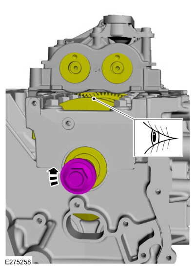
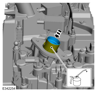
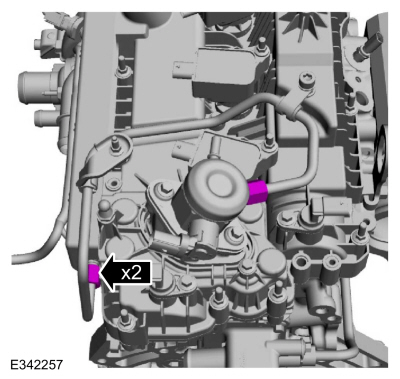
NOTICE:
The high-pressure fuel pump tappet cam lobe must be
positioned at zero lift before installing the high-pressure fuel pump
drive unit.
Rotate the crankshaft to position the camshaft at zero lift.
-
Inspect the high-pressure fuel pump tappet for flat spots or
scoring, especially in the indicated areas. If any damage is found,
inspect the high-pressure fuel pump and the high-pressure fuel pump
tappet drive lobe. Install new components as necessary.
-
Lubricate with clean engine oil and install the high-pressure fuel pump tappet.
-
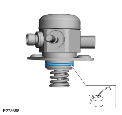
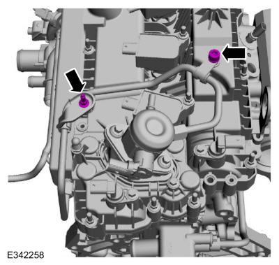
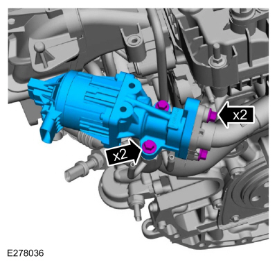
Install a new high-pressure fuel pump O-ring seal.
-
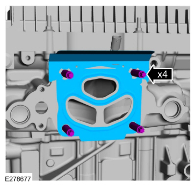
NOTE:
Install new bolts.
Install the high-pressure fuel pump, mounting plate and
alternately tighten each new bolt one complete revolution until seated
in 2 stages.
Torque:
Stage 1:
115 lb.in (13 Nm)
Stage 2:
45°
-
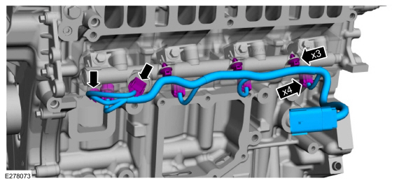
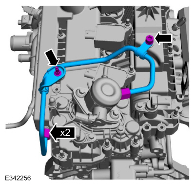
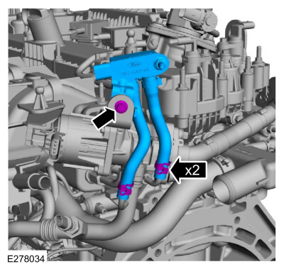
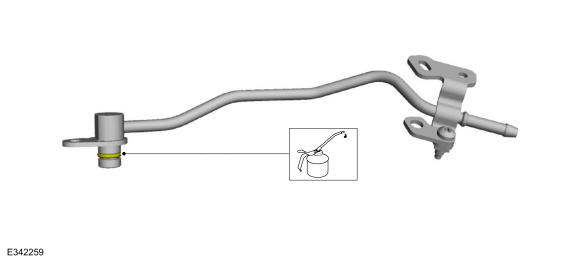
NOTE:
Install a new fuel tube.
-
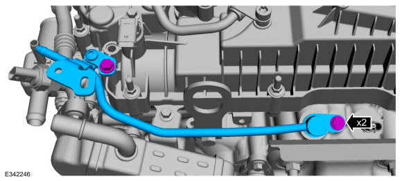
Install the fuel tube and the bolts finger-tight.
-
Install the flare nuts finger-tight.
-
Tighten the flare nuts in 2 stages.
Torque:
Stage 1:
89 lb.in (10 Nm)
Stage 2:
38°
-
Tighten the bolts.
Torque:
97 lb.in (11 Nm)
-
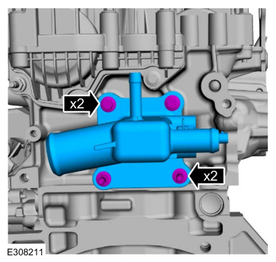
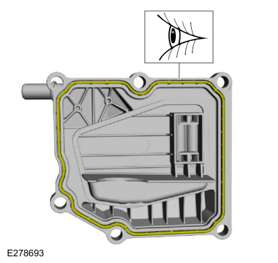
Inspect and replace the crankcase vent separator gasket, if damaged.
-
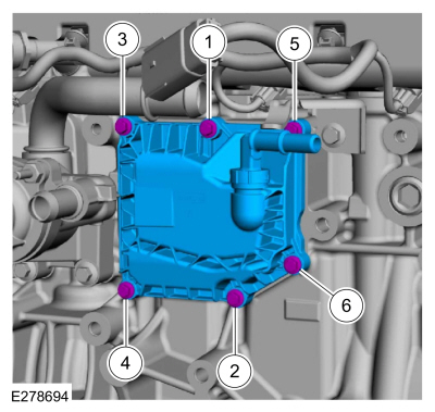
Install the crankcase vent separator and the bolts and tighten in sequence shown.
Torque:
97 lb.in (11 Nm)
-
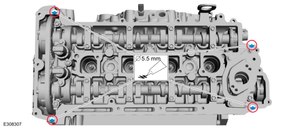
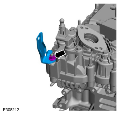
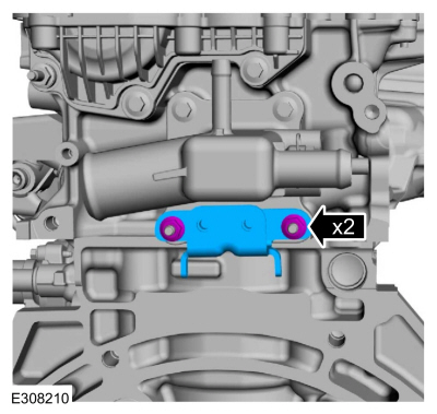
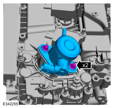
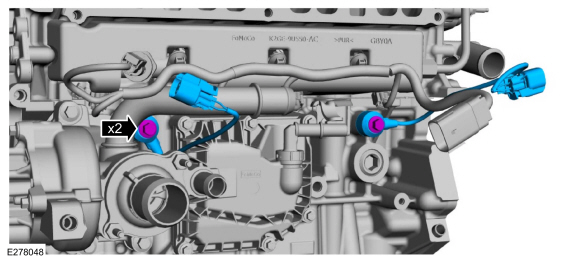
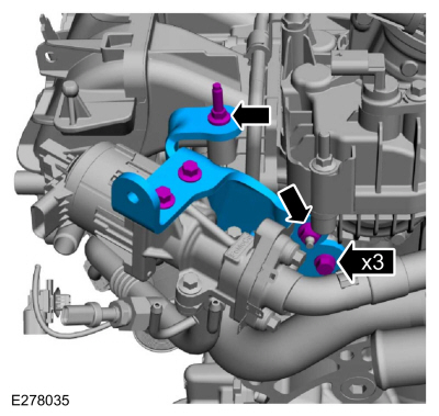
NOTICE:
The forward KS must be installed in the 5 o'clock position and the rearward KS
must be installed in the 3 o'clock position as shown in the graphic.
Failure to follow these instructions may result in damage to the engine.
Install the KS in their original position and install the bolts.
Torque:
18 lb.ft (25 Nm)
-
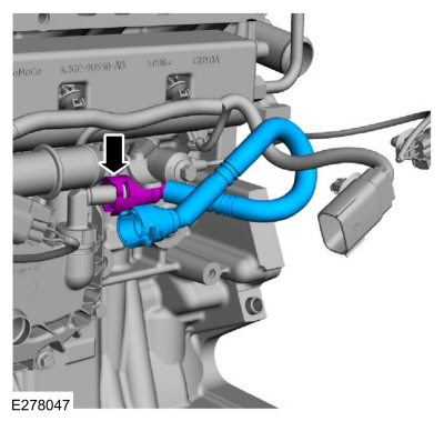
Connect the crankcase vent oil separator tube.
Refer to: Quick Release Coupling (310-00B Fuel System - General Information - 2.3L EcoBoost (199kW/270PS), General Procedures).
-
Install the coolant hose.
Use the General Equipment: Hose Clamp Remover/Installer
-
Inspect and replace if damaged.
-
Install the oil filter adapter and the bolts.
Torque:
18 lb.ft (25 Nm)
-
NOTICE:
If the engine is repaired or replaced because of upper
engine failure, typically including valve or piston damage, check the
intake manifold for metal debris. If metal debris is found, install a
new intake manifold. Failure to follow these instructions can result in
engine damage.
-
Visually inspect the intake manifold for metal debris.
-
-
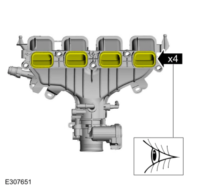
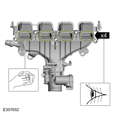
Visually inspect the intake manifold gaskets for nicks,
cuts and abrasions. If these conditions are not present, the gaskets may
be reused.
-
Clean and inspect all of the sealing surfaces of the intake manifold.
-
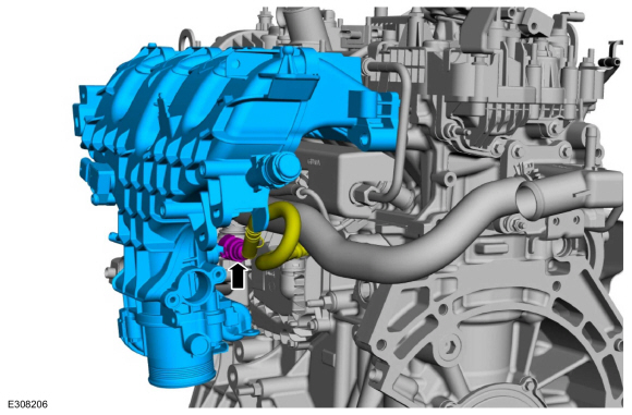
Install the intake manifold and connect the crankcase vent oil separator tube.
Refer to: Quick Release Coupling (310-00B Fuel System - General Information - 2.3L EcoBoost (199kW/270PS), General Procedures).
-
Position the intake manifold and install the bolts.
Torque:
18 lb.ft (25 Nm)
-
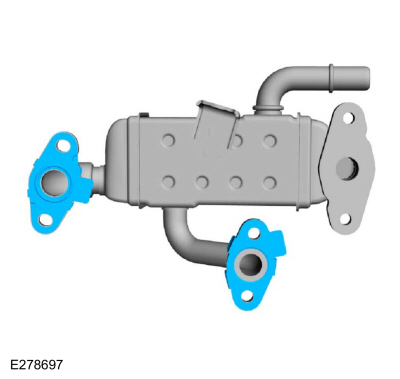
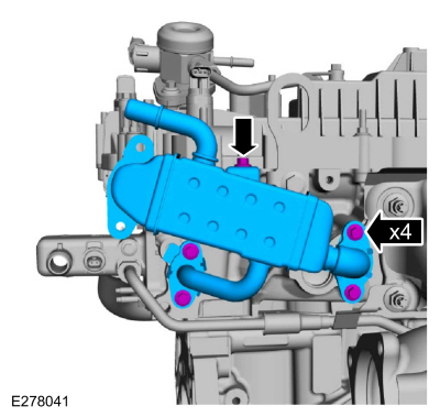
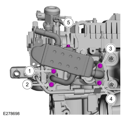
Install new EGR cooler gaskets.
-
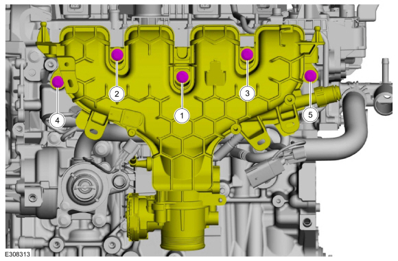
Install the EGR cooler and the bolts finger tight.
-
-
Tighten bolts 1 and 2.
Torque:
97 lb.in (11 Nm)
-
Retighten bolt 1.
Torque:
97 lb.in (11 Nm)
-
Tighten bolts 3 and 4.
Torque:
97 lb.in (11 Nm)
-
Retighten bolt 3.
Torque:
97 lb.in (11 Nm)
-
Tighten bolt 5.
Torque:
97 lb.in (11 Nm)
-
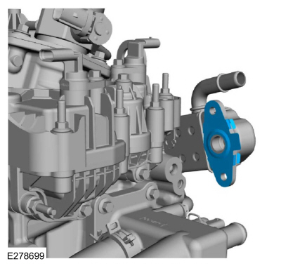
Install a new EGR inlet tube gasket.
-
Install the EGR inlet tube assembly and the bolts, stud bolt finger tight.
-
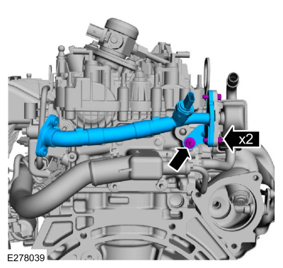
Install a new EGR outlet tube assembly O-ring seal and lubricate with clean engine oil.
-
Install the EGR outlet tube assembly and the bolts finger tight.
-
Install new EGR valve gaskets.
-
Install the EGR valve and bolts finger tight.
-
Install the EGR bracket the stud bolt, nut, bolts finger tight.
-
-
Tighten the stud bolt.
Torque:
97 lb.in (11 Nm)
-
Tighten the nut.
Torque:
97 lb.in (11 Nm)
-
Tighten the bolt.
Torque:
97 lb.in (11 Nm)
-
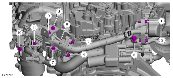
Tighten the bolts and stud bolt in sequence shown.
Torque:
Stage 1:
Tighten bolts 1 through 4 to:
97 lb.in (11 Nm)
Stage 2:
Tighten stud bolt 5 to:
18 lb.ft (25 Nm)
Stage 3:
Tighten bolts 6 through 11 to:
97 lb.in (11 Nm)
-
-
Install the EGR transducer assembly and the bolt.
Torque:
97 lb.in (11 Nm)
-
Install the EGR transducer hoses.
-
Attach the wiring connector retainers to the intake manifold.
-
Install the ground cable and the bolt.
Torque:
133 lb.in (15 Nm)
-
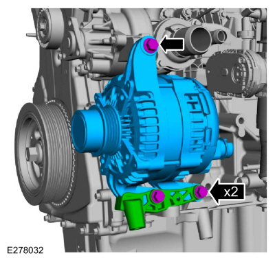
Install the generator, oil pan bracket and the bolts.
Torque:
18 lb.ft (25 Nm)
-
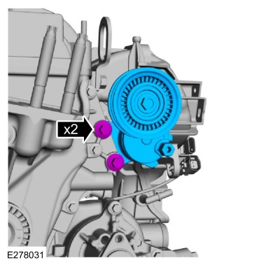
Install the accessory drive belt tensioner and the bolts.
Torque:
18 lb.ft (25 Nm)
-
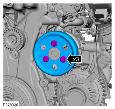
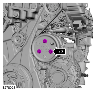
Install the coolant pump pulley and the bolts finger-tight.
-
-
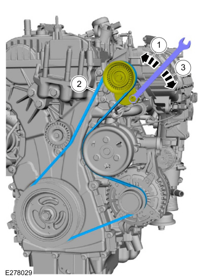
Install tool and release the tension on the accessory drive belt tensioner.
-
Install the accessory drive belt.
-
Release the tool and remove.
-
Tighten the coolant pump pulley bolts.
Torque:
18 lb.ft (25 Nm)
-
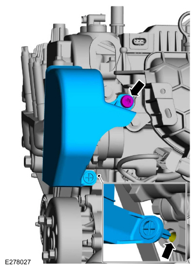
NOTE:
Make sure the molded pin goes into the boss on the engine front cover.
Install the shield and the bolt (Enhanced Hexalobular or
TORX PLUS ® Acument Intellectual Properties, LLC as the owner).
Torque:
18 lb.ft (25 Nm)
-
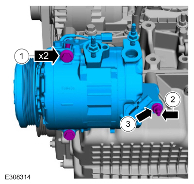
-
Install the A/C compressor and the bolts.
Torque:
18 lb.ft (25 Nm)
-
Install the A/C compressor stud.
Torque:
80 lb.in (9 Nm)
-
Install the A/C compressor nut.
Torque:
18 lb.ft (25 Nm)
-
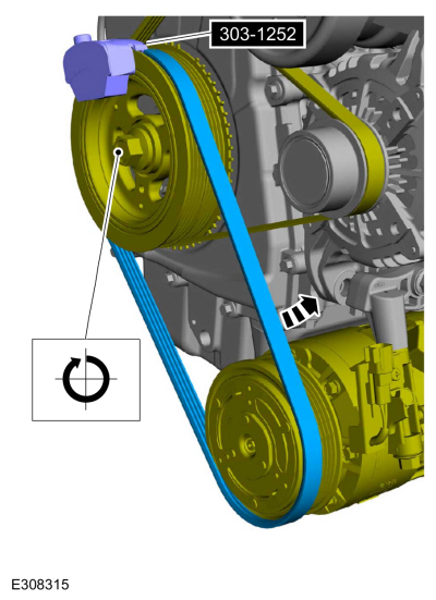
Using the special tool, install the A/C compressor belt.
Use Special Service Tool: 303-1252
Stretchy Belt Remover/ Installer Tool.
-
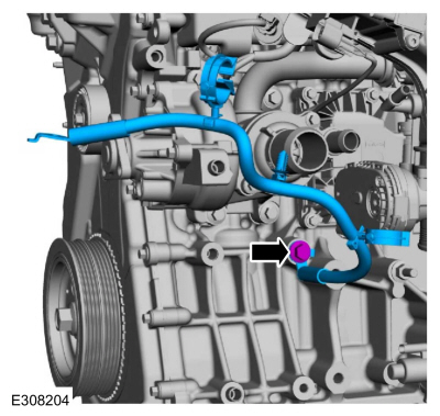
Lubricate the coolant tube O-ring seal with clean engine coolant.
-
NOTE:
The coolant tube must be fully seated prior to tighten the bolt.
Install the coolant tube and the bolts.
Torque:
97 lb.in (11 Nm)
-
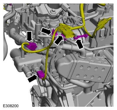
-
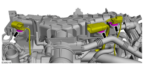
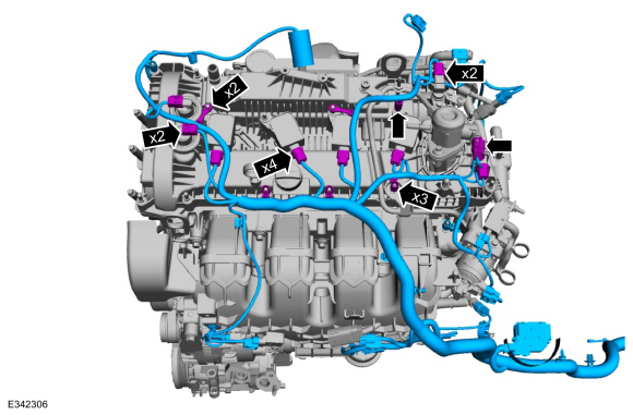
Install the engine wiring harness and attach the wiring harness retainers.
-
Connect the wiring harness electrical connectors.
-
-
Attach the wiring harness retainers.
-
Connect the wiring harness electrical connectors.
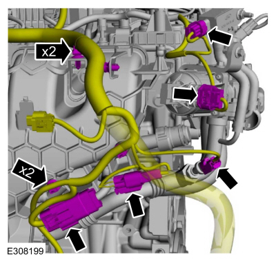
-
-
Attach the wiring harness retainers.
-
Connect the wiring harness electrical connectors.
-
-
Attach the wiring harness retainers.
-
Connect the wiring harness electrical connectors.
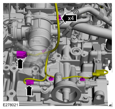
-
-
Attach the wiring harness retainers.
-
Connect the wiring harness electrical connectors.
-
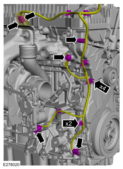
-
Attach the wiring harness retainers.
-
Connect the wiring harness electrical connectors.
-
Install the ground and the bolt.
Torque:
177 lb.in (20 Nm)
-
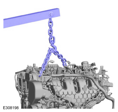
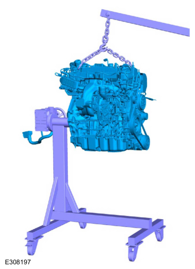
Install the engine lift equipment.
-
Remove engine from the mounting stand.
Use the General Equipment: Mounting Stand
-
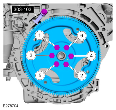
-
Install Special Service Tool: 303-103
(T74P-6375-A)
Holding Tool, Flywheel.
-
Tighten the bolts in sequence shown in 3 stages.
Torque:
Stage 1:
37 lb.ft (50 Nm)
Stage 2:
59 lb.ft (80 Nm)
Stage 3:
83 lb.ft (112 Nm)
DISASSEMBLY
NOTE:
If the piston and connecting rod are to be reinstalled, they
must be assembled in the same orientation. Mark the piston orientation
to the connecting rod reassembly...
Special Tool(s) /
General Equipment
307-566Retainer, Torque ConverterTKIT-2006C-FFMFLMTKIT-2006C-LMTKIT-2006C-ROW
Magnetic Socket
Floor Crane
Adjustable Mounting Arm
Hose Clamp Remover/Installer
Materials
Name
Specification
Motorcraft® Multi-Purpose Grease SprayXL-5-A
ESB-M1C93-B
Motorcraft® Threadlock and SealerTA-25-B
-
NOTIC..
Other information:
Overview
The
windshield wiper/washer system is activated by the wiper/washer switch.
The wiper/washer switch is mounted to the right side of the SCCM . The
following functions/ features of the windshield wiper/washer system are:
Mist wipe
Windshield wash (includes front camera wash, if equipped)
Courtesy wipe
Windshield wipers (low/high speed)
Intermittent wipers
..
Removal
NOTE:
Removal steps in this procedure may contain installation details.
Remove the retainers and the hood insulation.
Detach the windshield washer hose coupling.
Detach the retainers and position the windshield washer hose from the hood.
On both sides.
Index-mark the hood hinge location ..


 Disassembly and Assembly of Subassemblies - Piston
 Installation - Engine