Lincoln Corsair: Engine - 2.0L EcoBoost (177kW/240PS) – MI4 / Installation - Engine
Special Tool(s) /
General Equipment
 |
307-566
Retainer, Torque Converter
TKIT-2006C-FFMFLM
TKIT-2006C-LM
TKIT-2006C-ROW |
| Magnetic Socket |
| Floor Crane |
| Adjustable Mounting Arm |
| Hose Clamp Remover/Installer |
Materials
| Name |
Specification |
Motorcraft® Multi-Purpose Grease Spray
XL-5-A |
ESB-M1C93-B
|
Motorcraft® Threadlock and Sealer
TA-25-B |
-
|
NOTICE:
The turbocharger compressor vanes can be damaged by even the
smallest particles. When removing any turbocharger or engine air intake
system component, ensure that no debris enters the system. Failure to do
so may result in damage to the turbocharger.
LHD AWD/LHD FWD
-
Inspect the turbocharger or engine air intake system components and clean, if necessary.
-
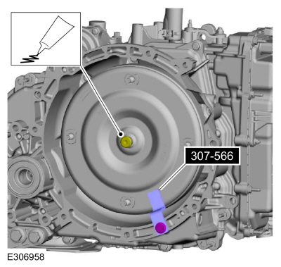
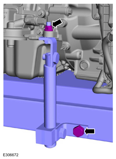
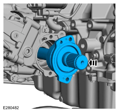
Lubricate the torque converter hub with multi-purpose grease.
Remove Special Service Tool: 307-566
Retainer, Torque Converter.
Material: Motorcraft® Multi-Purpose Grease Spray
/ XL-5-A
(ESB-M1C93-B)
-
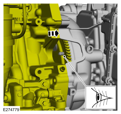
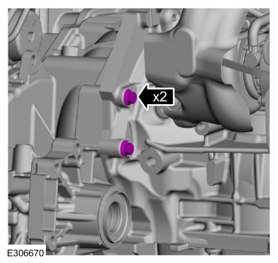
Inspect the engine block dowels. If the dowels are damaged or missing, install new engine block dowels.
-
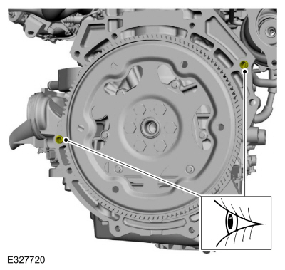
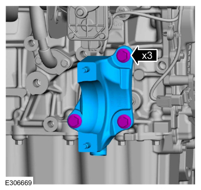
Align the torque converter stud marked during removal with the flexplate.
-
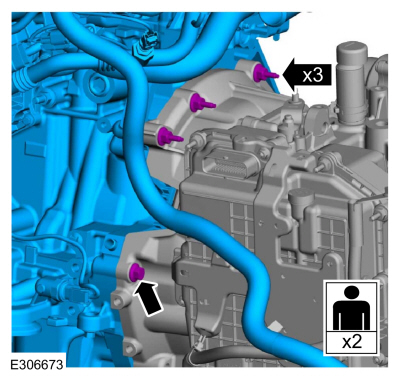
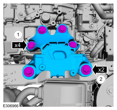
With the aid of an assistant, install engine to the transmission and install the bolts.
Torque:
35 lb.ft (48 Nm)
-
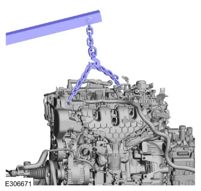
Install the adjustable mounting arm.
Use the General Equipment: Adjustable Mounting Arm
-
Remove the engine lift equipment.
Use the General Equipment: Floor Crane
LHD FWD
-
Install the engine-to-transmission bolts.
Torque:
35 lb.ft (48 Nm)
-
Install the halfshaft support bracket and the bolts.
Torque:
35 lb.ft (48 Nm)
LHD AWD
-
Install the engine-to-transmission bolts.
Torque:
35 lb.ft (48 Nm)
-
Install a new transfer case compression seal.
-
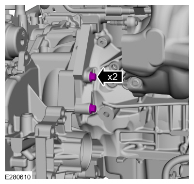
Install the transfer case and the bolts.
Torque:
76 lb.ft (103 Nm)
-
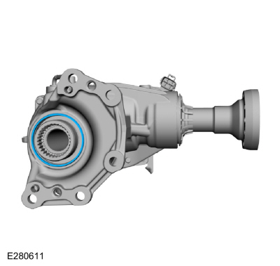
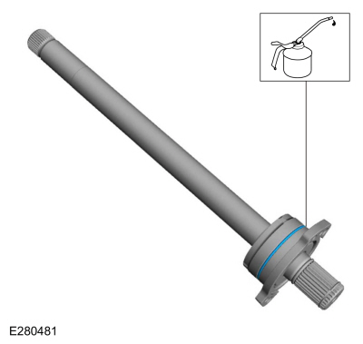
Install and lubricate the new transfer case axle shaft seal.
-
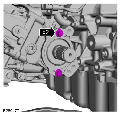
Install the transfer case axle shaft.
-
Install the bolts for the transfer case axle shaft.
Torque:
18 lb.ft (25 Nm)
-
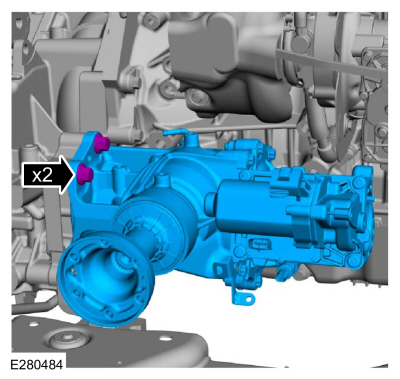
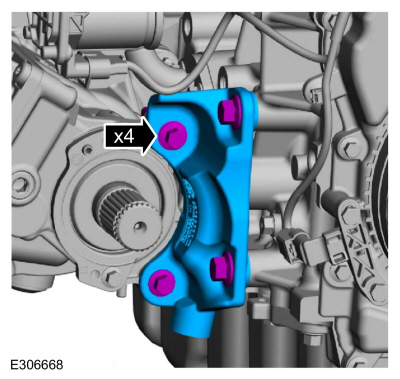
Install the transfer case support bracket and the bolts.
Torque:
35 lb.ft (48 Nm)
-
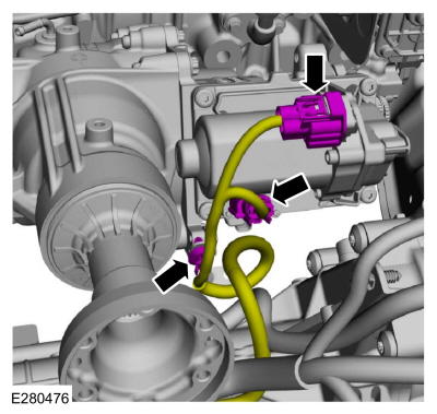
Connect the upper transfer case wiring harness electrical connectors and retainer.
-
Install the transfer case heat shield and the bolts.
Torque:
97 lb.in (11 Nm)
-
Connect the transfer case vent tube.
LHD AWD/LHD FWD
-
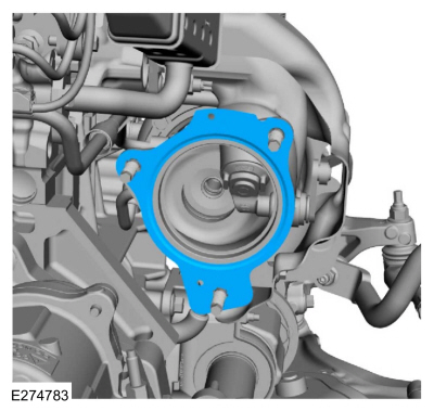
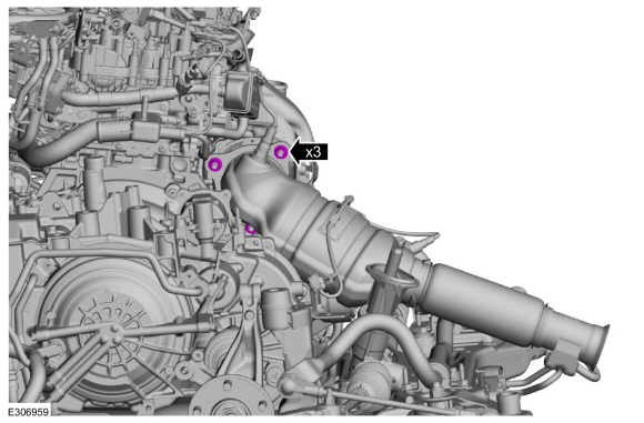
Install a new catalytic converter gasket.
-
NOTE:
Do not tighten the new catalytic converter-to-turbocharger nuts at this time.
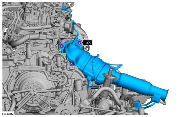
Install the catalytic converter and the new nuts finger-tight.
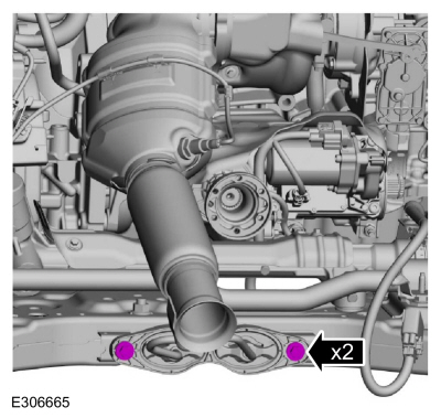
-
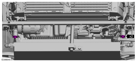
Install the catalytic converter support bracket-to-subframe bolts finger tight.
-
Tighten.
Torque:
35 lb.ft (48 Nm)
-
Tighten the catalytic converter support bracket-to-subframe bolts.
Torque:
18 lb.ft (25 Nm)
-
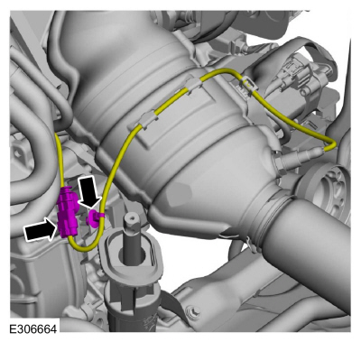
Connect the catalyst monitor sensor electrical connector and the retainer.
-
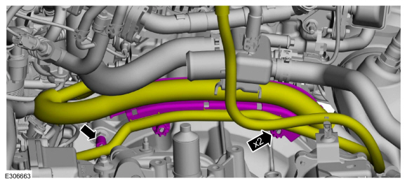
Attach the wiring harness retainers to transmission stud bolts.
-
Position the harness and attach the generator and A/C wiring harness retainers.
-
-
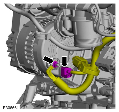
Connect the generator electrical connector.
-
Install the B+ cable and the nut.
Torque:
106 lb.in (12 Nm)
-
-
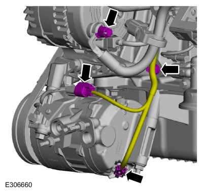
Connect the A/C compressor electrical connectors and the retainer.
-
Install the generator B+ cable nut cover.
-
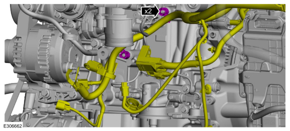
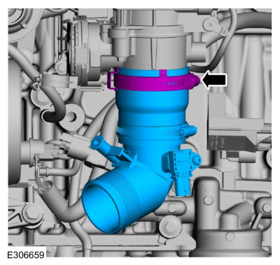
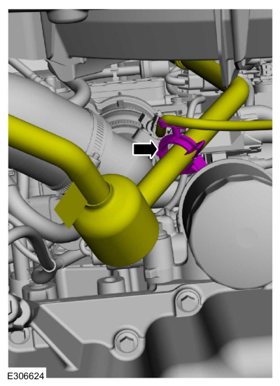
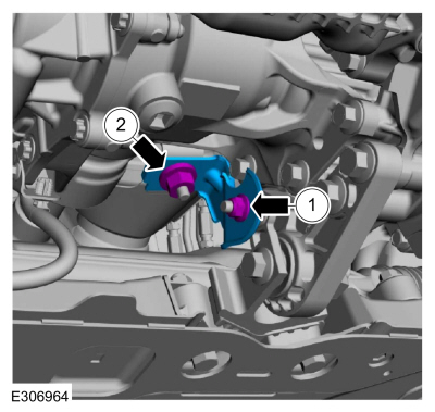
Install the CAC outlet pipe and tighten the clamp.
Torque:
44 lb.in (5 Nm)
-
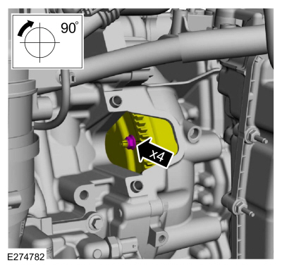
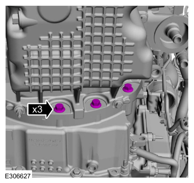
NOTE:
Only rotate the crankshaft in a clockwise direction.
Install the torque converter nuts.
Use the General Equipment: Magnetic Socket
Torque:
35 lb.ft (48 Nm)
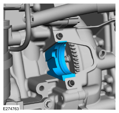
-
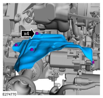
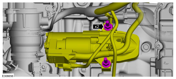
Install the stater motor isolator.
-
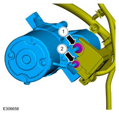
-
Install the battery cable harness and install the battery positive cable nut.
Torque:
106 lb.in (12 Nm)
-
Install the starter motor control wire nut.
Torque:
53 lb.in (6 Nm)
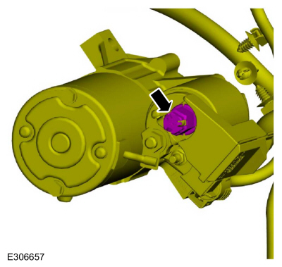
-
Install the battery positive cable nut cover.
-
Position the starter motor and install the stud bolts.
Torque:
35 lb.ft (48 Nm)
-
-
Install the starter motor bracket and the nuts.
Torque:
97 lb.in (11 Nm)
-
Attach the wiring harness retainers.
-
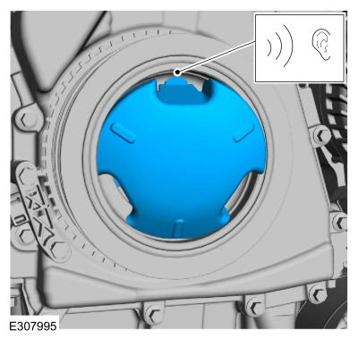
If equipped.
-
Align and insert 2 tabs of the crankshaft pulley
cover into the open spaces between the ribs of the crankcase pulley.
-
Press the third tab firmly into position until a snap is heard or felt.
-
Verify that the crankshaft pulley cover is securely in place.
-
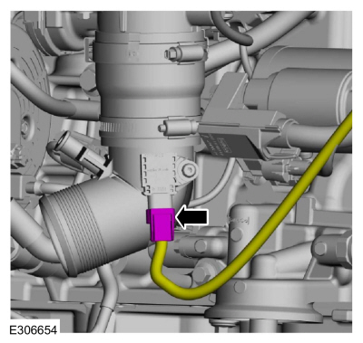
Connect the pressure sensor electrical connector.
-
Connect the transmission wiring harness connector and attach the retainers.
-
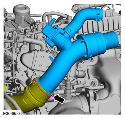
Connect the coolant hose to the thermostat housing and attach wiring harness retainer.
Use the General Equipment: Hose Clamp Remover/Installer
-
Install the CAC pipe, nut and the bolts.
Torque:
44 lb.in (5 Nm)
-
Install the CAC pipe and the clip.
-
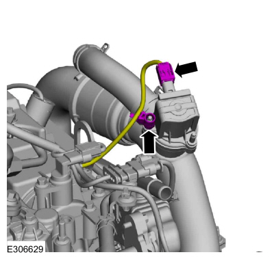
Connect the HO2S electrical connector and the retainer.
-
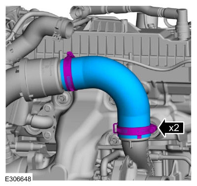
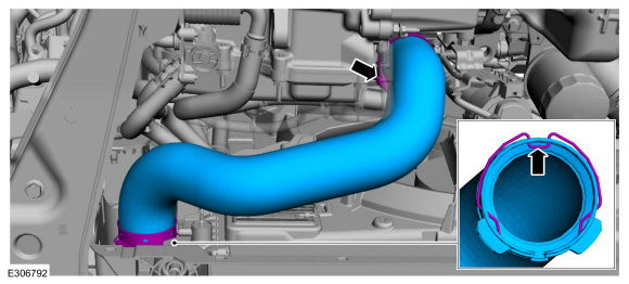
Install the CAC tube and tighten the clamps.
Torque:
44 lb.in (5 Nm)
-
Connect the CAC tube bypass valve electrical connector and wire retainer.
-
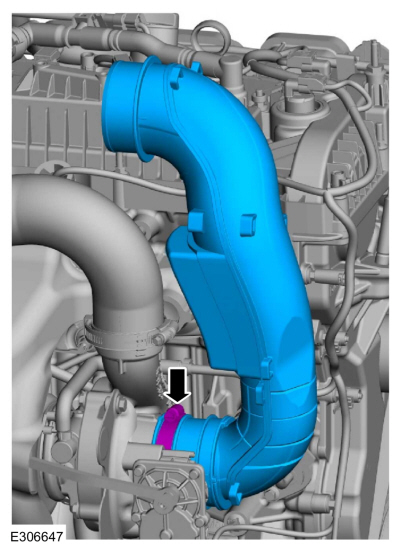
Install the CAC pipe and tighten the clamp.
Torque:
27 lb.in (3 Nm)
-
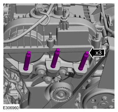
Tighten the engine mount studs.
Torque:
106 lb.in (12 Nm)
-
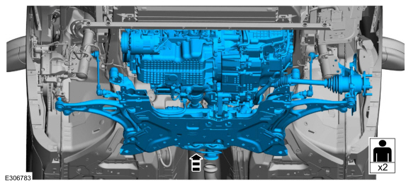
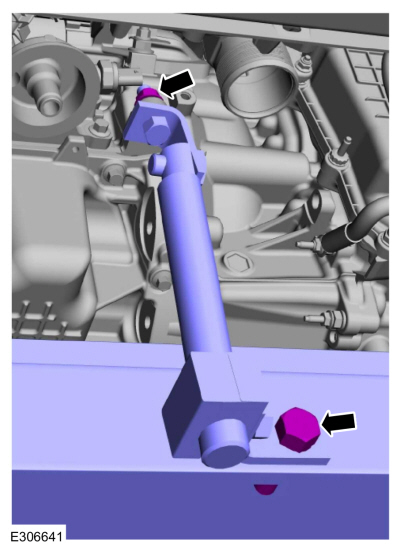
With the aid of an assistant and using the powertrain jack, raise the powertrain and subframe as an assembly.
-
-
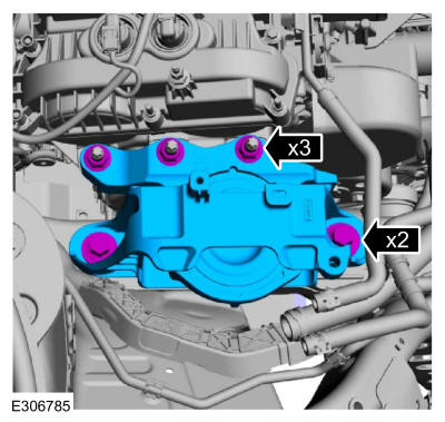
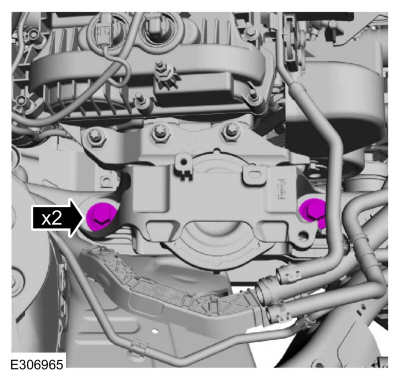
Install the engine mount and the new nuts.
Torque:
81 lb.ft (110 Nm)
-
Install the new bolts finger tight.
-
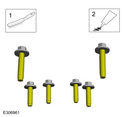
-
Clean the transmission support insulator bolts using a wire brush.
-
Apply Motorcraft® Threadlock and Sealer to the threads.
Material: Motorcraft® Threadlock and Sealer
/ TA-25-B
-
Install the transmission support insulator and the bolts finger tight.
-
Tighten the transmission support insulator-to-transmission bolts.
Torque:
129 lb.ft (175 Nm)
-
Tighten the transmission support insulator-to-frame rail bolts.
Torque:
184 lb.ft (250 Nm)
-
Install the new forward subframe bolts finger tight.
-
-
Install the subframe brackets and the new rearward subframe bolts finger tight.
-
Install the new subframe bracket bolts finger tight.
-
Tighten the forward subframe bolts.
Torque:
85 lb.ft (115 Nm)
-
-
Tighten.
Torque:
Stage 1:
159 lb.ft (215 Nm)
Stage 2:
60°
-
Tighten.
Torque:
46 lb.ft (63 Nm)
-
Remove the adjustable mounting arm and the lift table.
-
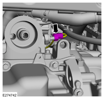
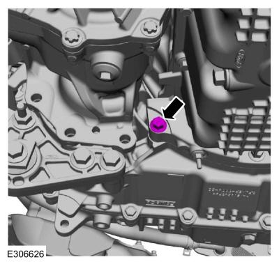
Connect the EOP sensor electrical connector.
-
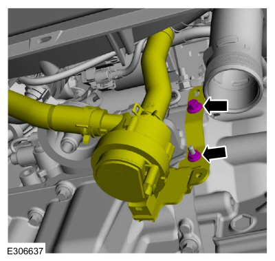
Position the auxiliary coolant pump and install the nut and bolt.
Torque:
80 lb.in (9 Nm)
-
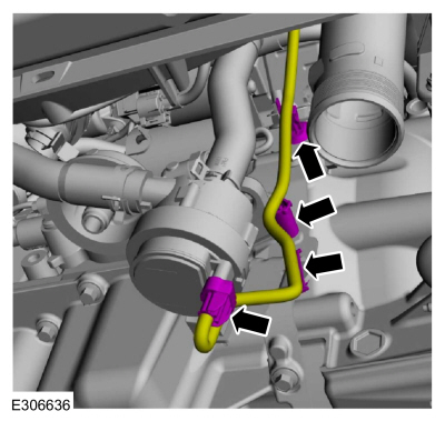
Connect the auxiliary coolant pump electrical connector and attach the wiring harness retainers.
-
Connect the steering gear electrical connector behind the RH side of subframe.
-
-
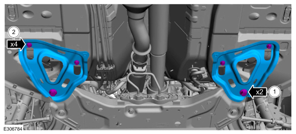
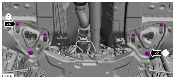
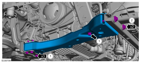
Install the RH subframe support bracket and the new bolts.
Torque:
22 lb.ft (30 Nm)
-
Install the subframe support bracket bolts.
Torque:
22 lb.ft (30 Nm)
-
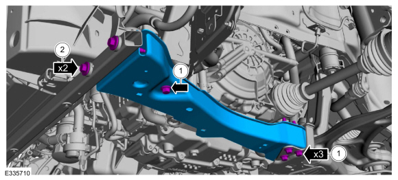
-
Install the LH subframe support bracket and the new bolts.
Torque:
22 lb.ft (30 Nm)
-
Install the subframe support bracket bolts.
Torque:
22 lb.ft (30 Nm)
-
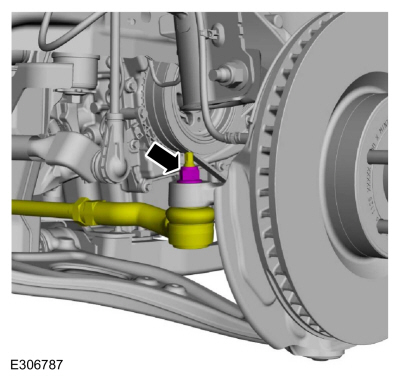
Install the RH tie rod to the wheel knuckle and install the nut.
Torque:
35 lb.ft (48 Nm)
-
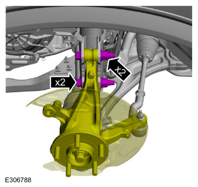
Install the new bolts and nuts for the LH strut.
Torque:
Stage 1:
103 lb.ft (140 Nm)
Stage 2:
120°
-
Install the LH front brake disc.
Refer to: Brake Disc (206-03 Front Disc Brake, Removal and Installation).
-
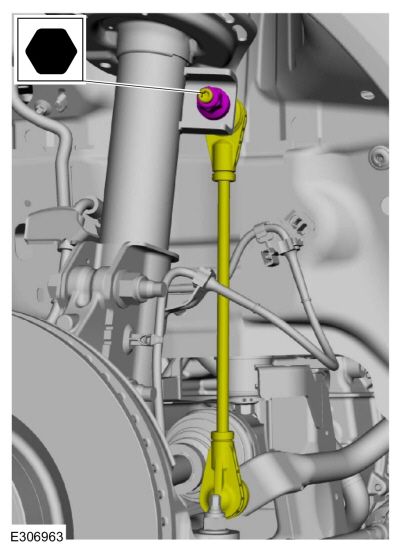
NOTICE:
Use the internal or external hex-holding feature to
prevent the ball and stud from turning while removing or installing the
stabilizer bar link nuts. The link boot seal must not be allowed to
twist while tightening the link nuts or damage to the boot seal will
occur.
Position the RH sway bar link and install the new nut.
Torque:
81 lb.ft (110 Nm)
-
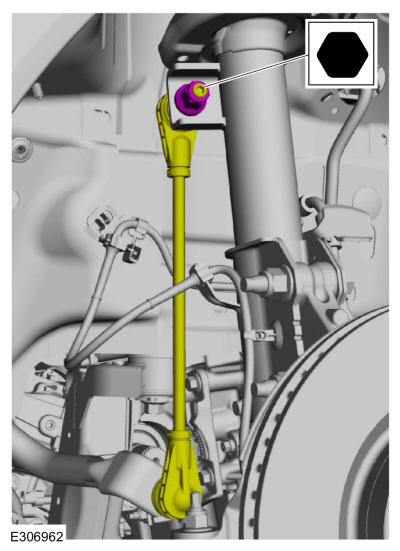
NOTICE:
Use the internal or external hex-holding feature to
prevent the ball and stud from turning while removing or installing the
stabilizer bar link nuts. The link boot seal must not be allowed to
twist while tightening the link nuts or damage to the boot seal will
occur.
Position the LH sway bar link and install the new nut.
Torque:
81 lb.ft (110 Nm)
-
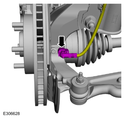
Connect the LH anti-lock sensor.
-
Install the transmission-to-engine bolts.
Torque:
35 lb.ft (48 Nm)
-
Install the oil pan-to-transmission bolt.
Torque:
35 lb.ft (48 Nm)
-
-
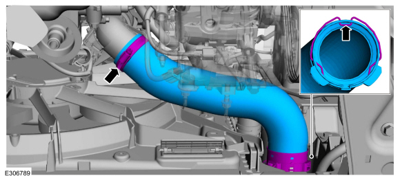
Install the intake CAC pipe and tighten the clamp.
Torque:
48 lb.in (5.4 Nm)
-
Install the CAC pipe clip.
-
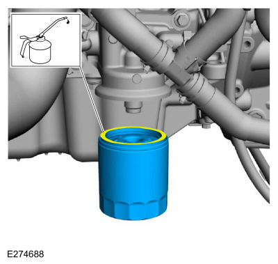
Lubricate the oil filter sealing surface and install.
Torque:
Stage 1:
71 lb.in (8 Nm)
Stage 2:
180°
-
Attach the wiring harness retainer to A/C line.
-
NOTICE:
During the removal of components, cap, tape or
otherwise appropriately protect all openings to prevent the ingress of
dirt or other contamination. Remove protective materials prior to
installation.
-
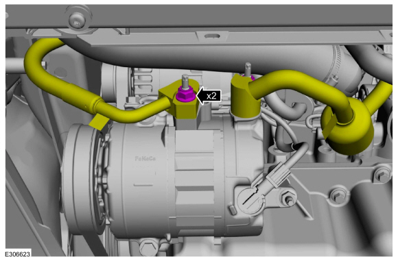
Install new the O-ring seals and gasket seals.
-
Install A/C compressor and connect the A/C lines.
Torque:
159 lb.in (18 Nm)
-
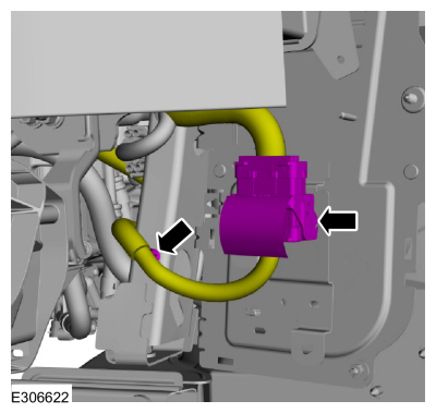
Connect the engine harness electrical connector and the wiring harness retainer.
-
-
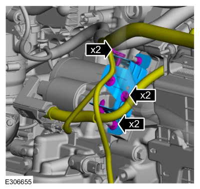
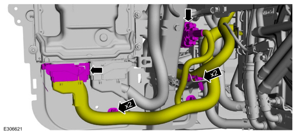
Connect the PCM electrical connector and the retainers.
-
Connect the engine harness electrical connector and retainers.
-
Install the PCM cover and the bolts.
Torque:
28 lb.in (3.2 Nm)
LHD AWD
-
Install the new bottom transfer case bolts.
Torque:
76 lb.ft (103 Nm)
-
Connect the lower transfer case wiring harness electrical connector and retainer.
-
Install the following items:
-
Install the rear driveshaft.
Refer to: Rear Driveshaft (205-01 Driveshaft, Removal and Installation).
-
Install the AWD RH halfshaft.
Refer to: Front Halfshaft RH - AWD (205-04 Front Drive Halfshafts, Removal and Installation).
LHD FWD
-
Install the FWD RH halfshaft.
Refer to: Front Halfshaft RH - 2.0L EcoBoost (177kW/240PS) – MI4, FWD
(205-04 Front Drive Halfshafts, Removal and Installation).
-
Position the exhaust and install the new clamp and tighten.
Torque:
17 lb.ft (23 Nm)
LHD AWD/LHD FWD
-
-
Install the catalytic converter support bracket and the nut.
Torque:
35 lb.ft (48 Nm)
-
Install the catalytic converter support bracket nut.
Torque:
41 lb.ft (55 Nm)
-
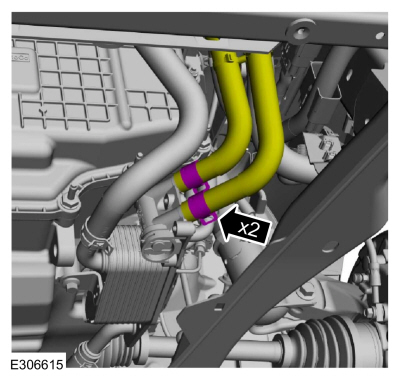
Connect the transmission fluid cooler tubes.
Use the General Equipment: Hose Clamp Remover/Installer
-
-
Install the outlet CAC pipe and tighten the clamp.
Torque:
48 lb.in (5.4 Nm)
-
Install the CAC pipe clip.
-
Install the following items:
-
Install the front bumper cover.
Refer to: Front Bumper Cover (501-19 Bumpers, Removal and Installation).
-
Install the RH and LH fender splash shields.
Refer to: Fender Splash Shield (501-02 Front End Body Panels, Removal and Installation).
-
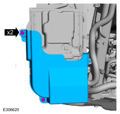
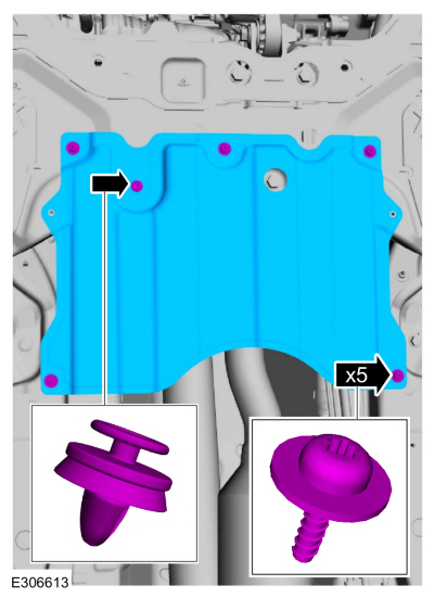
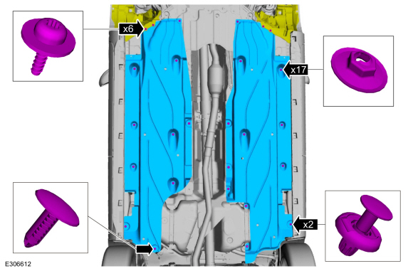
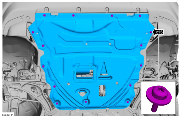
Install the underbody shield and the retainers.
Torque:
22 lb.in (2.5 Nm)
-
Install the underbody shields and the retainers.
Torque:
22 lb.in (2.5 Nm)
-
Install the following items:
-
Install the RH and LH front suspension height sensors.
Refer to: Front Suspension Height Sensor (204-05 Vehicle Dynamic Suspension, Removal and Installation).
-
Install the front wheels and tires.
Refer to: Wheel and Tire (204-04A Wheels and Tires, Removal and Installation).
-
Tighten the engine mount bolts.
Torque:
129 lb.ft (175 Nm)
-
-
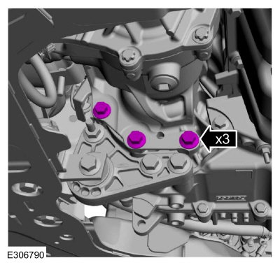
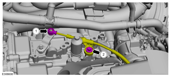
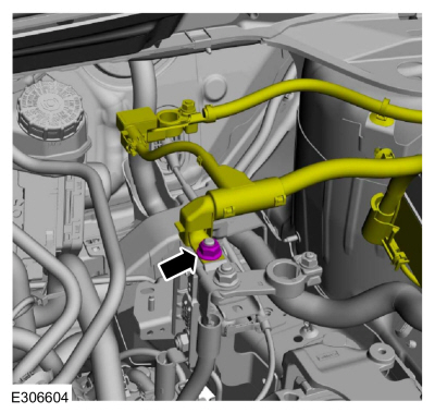
Install the fuel tube and connect the fuel tube spring lock couplings.
-
Attach the fuel tube retainer.
-
NOTE:
When installing the high-pressure fuel pump noise
insulator, spreading the openings will reduce the risk of damage.
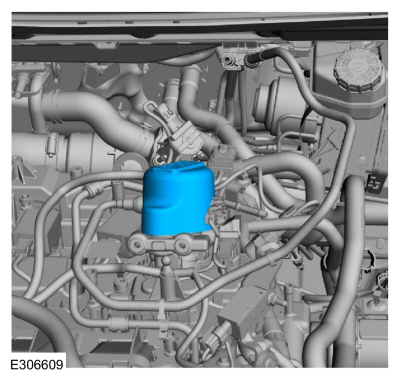
Install the high-pressure fuel pump noise insulator.
-
-
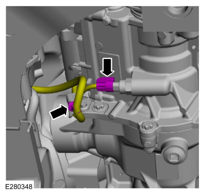
Position back the manual park release cable and install the bolt.
Torque:
177 lb.in (20 Nm)
-
Connect the manual park release cable to the manual control lever.
-
-
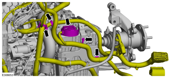
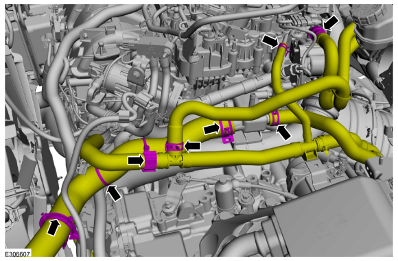
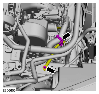
Connect the coolant hoses.
Use the General Equipment: Hose Clamp Remover/Installer
-
Connect heater hose to the EGR cooler.
-
Attach the coolant hose retainers.
-
-
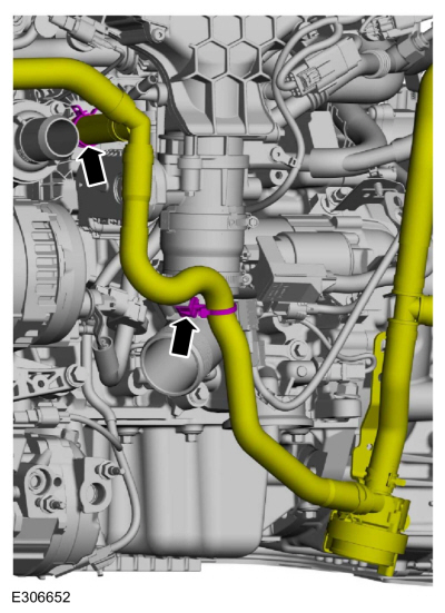
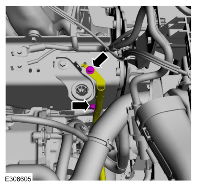
Install the degas bottle coolant hose and the clamp.
Use the General Equipment: Hose Clamp Remover/Installer
-
Attach the degas bottle coolant hose retainers.
-
Position the ground wire, attach the retainer and install the bolt.
Torque:
22 lb.ft (30 Nm)
-
Position the battery feed cable to the positive battery cable and install the nut.
Torque:
133 lb.in (15 Nm)
-
Position the ground wire, attach the retainer and install the bolt.
Torque:
97 lb.in (11 Nm)
-
Position the A/C line bracket and install the bolt.
Torque:
80 lb.in (9 Nm)
-
-
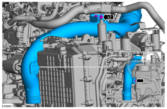
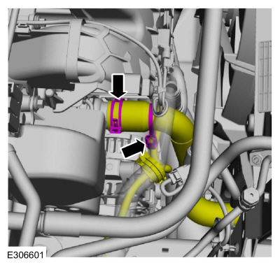
Connect the lower radiator hose to the thermostat housing.
Use the General Equipment: Hose Clamp Remover/Installer
-
Connect the lower radiator hose retainer.
-
-
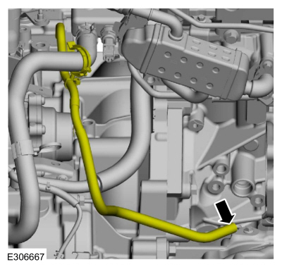
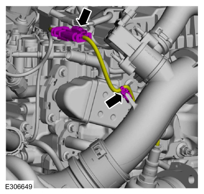
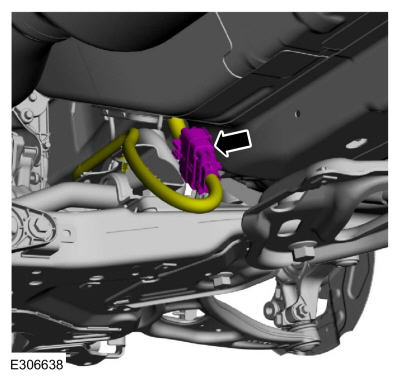
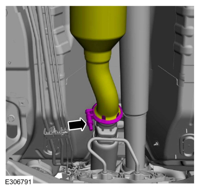
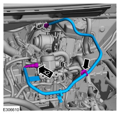
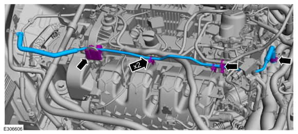
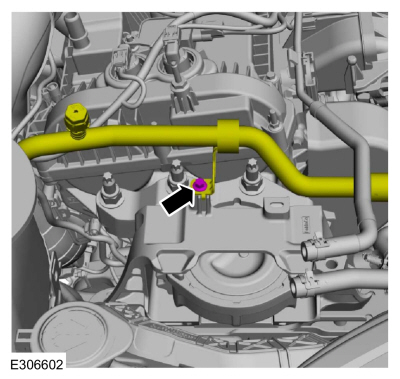
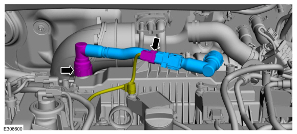
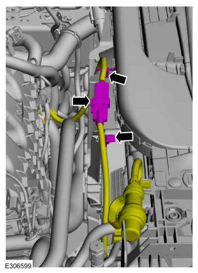
Install the new crankcase vent tube.
-
If the replacement crankcase vent tube part comes with no crankcase pressure sensor, reprogram the PCM .
Refer to: Module Programming (418-01 Module Configuration, General Procedures).
-
If the replacement crankcase vent tube came without a
crankcase pressure sensor, tape the wiring harness electrical connector
back to the wiring harness.
-
If the replacement crankcase vent tube comes with a
crankcase pressure sensor, connect the wiring harness electrical
connector.
-
If equipped, connect the block heater electrical connector and attach the wiring harness retainers.
-
Install the following items:
-
Install the EVAP canister purge valve.
Refer to: Evaporative Emission Canister Purge Valve (303-13A
Evaporative Emissions - 2.0L EcoBoost (177kW/240PS) – MI4, Removal and
Installation).
-
Install the battery tray.
Refer to: Battery Tray - 2.0L EcoBoost (177kW/240PS) – MI4/2.3L
EcoBoost (199kW/270PS) (414-01 Battery, Mounting and Cables, Removal and
Installation).
-
Install the air cleaner.
Refer to: Air Cleaner (303-12A Intake Air Distribution and Filtering -
2.0L EcoBoost (177kW/240PS) – MI4, Removal and Installation).
-
Install the air cleaner outlet pipe.
Refer to: Air Cleaner Outlet Pipe (303-12A Intake Air Distribution and
Filtering - 2.0L EcoBoost (177kW/240PS) – MI4, Removal and
Installation).
-
Install the degas bottle.
Refer to: Degas Bottle (303-03A Engine Cooling - 2.0L EcoBoost (177kW/240PS) – MI4, Removal and Installation).
-
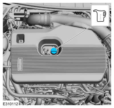
Fill the engine with clean engine oil.
Refer to: Specifications (303-01A Engine - 2.0L EcoBoost (177kW/240PS) – MI4, Specifications).
-
Fill the cooling system.
Refer to: Engine Cooling System Draining, Vacuum Filling and Bleeding
(303-03A Engine Cooling - 2.0L EcoBoost (177kW/240PS) – MI4, General
Procedures).
-
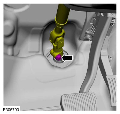
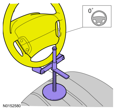
Position steering column shaft and install a new bolt.
Torque:
46 lb.ft (63 Nm)
-
Remove the holding device.
-
Charge the A/C system.
Refer to: Air Conditioning (A/C) System Recovery,
Evacuation and Charging - Vehicles With: R1234YF Refrigerant (412-00
Climate Control System - General Information)
.
Refer to: Air Conditioning (A/C) System Recovery,
Evacuation and Charging - Vehicles With: R1234YF Refrigerant (412-00
Climate Control System - General Information)
.
-
Check the transmission fluid level.
Refer to: Transmission Fluid Level Check (307-01A Automatic
Transmission - 8-Speed Automatic Transmission – 8F35/8F40, General
Procedures).
-
If equipped with AWD , check the transfer case fluid level.
-
Install the underbody shield and the retainers.
Torque:
13 lb.in (1.5 Nm)
-
Pressurize the fuel system.
Refer to: Fuel System Pressure Release (310-00A Fuel System - General
Information - 2.0L EcoBoost (177kW/240PS) – MI4, General Procedures).
-
Start and check the exhaust system for leaks.
-
Use the Powertrain Control Module (PCM) Misfire Monitor Profile Correction routine in the diagnostic scan tool.
Other information:
Lubricants, Fluids, Sealants and Adhesives Vehicles Built On Or Before: 31-December-2019
NAME
SPECIFICATION
FILL CAPACITY
Motorcraft® Orange Concentrated Antifreeze/Coolant / VC-3-B
WSS-M97B44-D
8.7 qt (8.2L)
Motorcraft® Orange Prediluted Antifreeze/Coolant / VC-3DIL-B
WSS-M97B44-D2
8.7 qt (8.2L)
..
Special Tool(s) /
General Equipment
Hose Clamp Remover/Installer
Removal
NOTICE:
During engine repair procedures, cleanliness is extremely
important. All parts must be thoroughly cleaned and any foreign
material, including any material created while cleaning gasket surfaces,
that enters the oil passages, coolant passages or the oil pan, can
cause engine failure.
NOTICE:
Th..