Lincoln Corsair: Electronic Engine Controls - 2.0L EcoBoost (177kW/240PS) – MI4 / Removal and Installation - Turbocharger Bypass Valve
Lincoln Corsair 2020-2026 Service Manual / Powertrain / Engine / Electronic Engine Controls - 2.0L EcoBoost (177kW/240PS) – MI4 / Removal and Installation - Turbocharger Bypass Valve
Materials
| Name | Specification |
|---|---|
| Motorcraft® Silicone Brake Caliper Grease and Dielectric Compound XG-3-A |
ESA-M1C200-A ESE-M1C171-A |
Removal
NOTE: Removal steps in this procedure may contain installation details.
-
NOTICE: Do not pull the engine appearance cover forward or sideways to remove. Failure to press straight upward on the underside of the cover at the attachment points may result in damage to the cover or engine components.
-
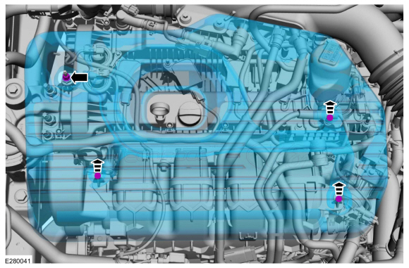
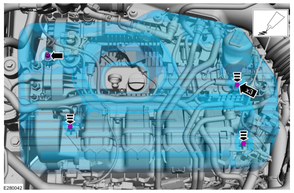
Remove the engine appearance cover nut.
-
Place your hand under the engine appearance cover at
each grommet location and pull straight up to release each grommet from
the studs.
-
After all of the grommets have been released from the studs, remove the appearance cover from the engine.
-
Remove the engine appearance cover nut.
 |
-
-
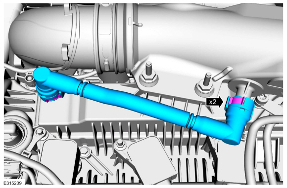
Remove the crankcase vent tube.
Refer to: Quick Release Coupling (310-00 Fuel System - General Information - 2.0L EcoBoost (177kW/240PS) - MI4) .
-
Remove the crankcase vent tube.
 |
-
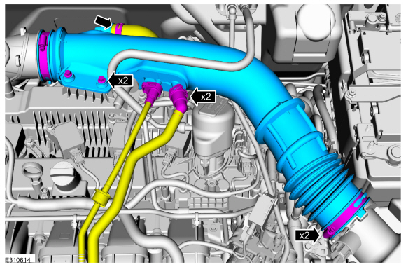
Remove the air cleaner outlet pipe.
-
Disconnect the vent tubes.
Refer to: Quick Release Coupling (310-00 Fuel System - General Information - 2.0L EcoBoost (177kW/240PS) - MI4) .
-
Loosen the clamps.
Torque: 44 lb.in (5 Nm)
-
Remove the bolts and the air cleaner outlet tube.
Torque: 62 lb.in (7 Nm)
-
Disconnect the vent tubes.
 |
-
-
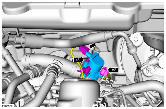
Disconnect the electrical connector and harness retainers.
-
Remove the bolts and the turbocharger bypass valve.
Torque: 71 lb.in (8 Nm)
-
Disconnect the electrical connector and harness retainers.
 |
Installation
-
To install, reverse the removal procedure.
-
-
NOTE: Lubricating the grommets with silicone grease will aid in the installation of the engine appearance cover, and any future removal and installation of the cover.
Lubricate each grommet with silicone grease.
Material: Motorcraft® Silicone Brake Caliper Grease and Dielectric Compound / XG-3-A (ESA-M1C200-A) (ESE-M1C171-A)
-
Position the engine appearance cover onto engine with the grommets aligned with the studs.
-
Press down on the engine appearance cover at each grommet location to attach the grommets onto the studs.
-
Install the engine appearance cover nut.
Torque: 44 lb.in (5 Nm)
-
If the engine appearance cover stud bolt is loosened
or removed, it must be installed/tightened into the valve cover.
Torque: 62 lb.in (7 Nm)
-
 |
 Removal and Installation - Powertrain Control Module (PCM)
Special Tool(s) /
General Equipment
Ford Diagnostic Equipment
Removal
NOTE:
Removal steps in this procedure may contain installation details...
 Removal and Installation - Variable Camshaft Timing (VCT) Oil Control Solenoid
Removal
NOTE:
Removal steps in this procedure may contain installation details.
Remove the valve cover.
Refer to: Valve Cover (303-01A Engine - 2...
Other information:
Lincoln Corsair 2020-2026 Service Manual: Removal and Installation - Rear Head Restraint Guide Sleeve
Special Tool(s) / General Equipment Flat Headed Screw Driver Removal Outboard head restraint guide sleeves Push the rear seat outboard head restraint release buttons. Remove the rear seat outboard head restraint...
Lincoln Corsair 2020-2026 Service Manual: Description and Operation - Auto-Start-Stop Accumulator
Auto-Start-Stop Accumulator components Item Description 1 Bolts (2 required) 2 Studbolt 3 Auto-Start-Stop accumulator 4 Seal 5 O-ring seal (2 required) 6 Solenoid 7 Transmission case Mechanical Operation When the engine is running, line pressu..
Categories
- Manuals Home
- 1st Generation Lincoln Corsair Owners Manual
- 1st Generation Lincoln Corsair Service Manual
- Memory Function
- Auto Hold (IF EQUIPPED)
- Technical Specifications
- New on site
- Most important about car
Selecting a Drive Mode. DRIVE MODES
Selecting a Drive Mode
Note: Drive mode changes may not be available when the ignition is off.
Copyright © 2026 www.licorsair.com