Lincoln Corsair: Fuel Charging and Controls - Turbocharger - 2.0L EcoBoost (177kW/240PS) – MI4 / Removal and Installation - Turbocharger
Materials
| Name | Specification |
|---|---|
| Motorcraft® Metal Brake Parts Cleaner PM-4-A, PM-4-B, APM-4-C |
- |
Removal
NOTICE: The turbocharger compressor vanes can be damaged by even the smallest particles. When removing any turbocharger or engine air intake system component, ensure that no debris enters the system. Failure to do so may result in damage to the turbocharger.
NOTICE: Special attention needs to be given to the sealing ports for the oil supply, the oil return, and the coolant tubes, on turbocharged engines. The sealing ports must be totally clean and free from O-ring residue, have no damage to the sealing surface and the tubes to ensure that there are no leaks or repeat repairs.
All vehicles
-
Drain the cooling system.
Refer to: Engine Cooling System Draining, Vacuum Filling and Bleeding (303-03A Engine Cooling - 2.0L EcoBoost (177kW/240PS) – MI4, General Procedures).
AWD (all-wheel drive) vehicles
-
Remove the power transfer unit.
Refer to: Power Transfer Unit - Vehicles With: Power Transfer Unit Oil-to-Coolant Cooler (307-07B Power Transfer Unit - 2.0L EcoBoost (177kW/240PS) – MI4, Removal).
Refer to: Power Transfer Unit - Vehicles With: Power Transfer Unit Oil-to-Coolant Cooler (307-07B Power Transfer Unit - 2.0L EcoBoost (177kW/240PS) – MI4, Installation).
FWD (front wheel drive) vehicles
-
Remove the right front wheel and tire.
Refer to: Wheel and Tire (204-04A Wheels and Tires, Removal and Installation).
All vehicles
-
Remove the upper air cleaner outlet pipe.
Refer to: Air Cleaner Outlet Pipe (303-12A Intake Air Distribution and Filtering - 2.0L EcoBoost (177kW/240PS) – MI4, Removal and Installation).
-
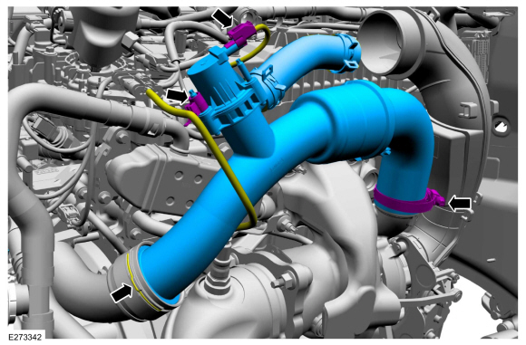
Disconnect the turbocharger bypass valve electrical
connector, then detach the harness retainer from the stud bolt. Release
the charge air cooler upper inlet pipe retaining clip. Loosen the charge
air cooler upper inlet pipe clamp, then remove the charge air cooler
upper inlet pipe.
 |
-
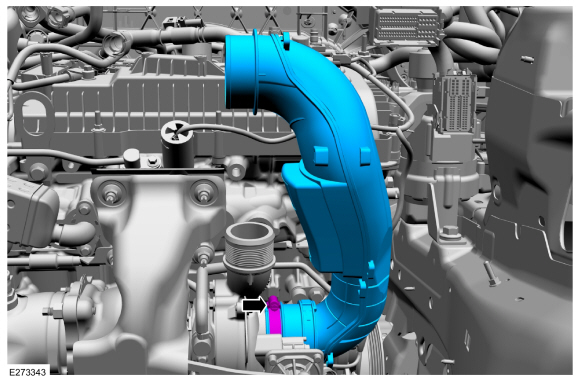
Loosen the lower air cleaner outlet pipe clamp, then remove the lower air cleaner outlet pipe.
 |
FWD (front wheel drive) vehicles
-
Remove the catalytic converter.
Refer to: Catalytic Converter (309-00A Exhaust System - 2.0L EcoBoost (177kW/240PS) – MI4, Removal and Installation).
Refer to: Catalytic Converter (309-00A Exhaust System - 2.0L EcoBoost (177kW/240PS) – MI4, Removal and Installation).
AWD (all-wheel drive) vehicles
-
Remove the battery tray.
Refer to: Battery Tray - 2.0L EcoBoost (177kW/240PS) – MI4/2.3L EcoBoost (199kW/270PS) (414-01 Battery, Mounting and Cables, Removal and Installation).
-
Remove and discard the catalytic converter nuts, then move the catalytic converter out of the way.
 |
-
Remove and discard the gasket.
 |
All vehicles
-
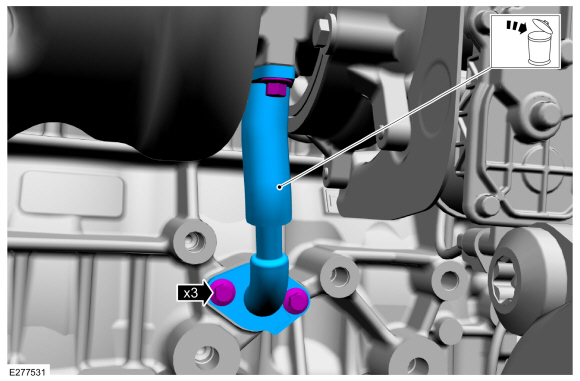
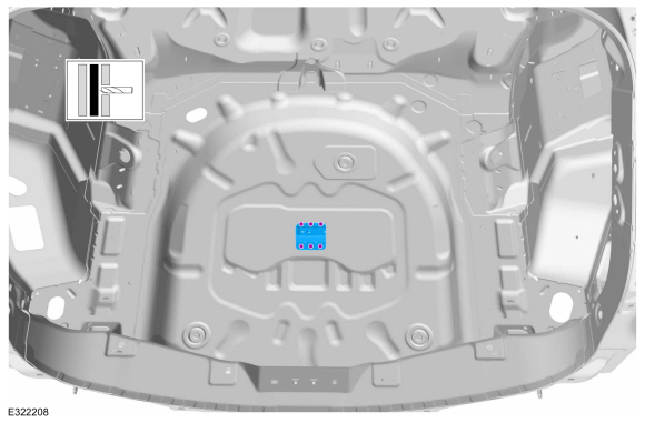
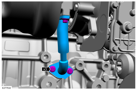
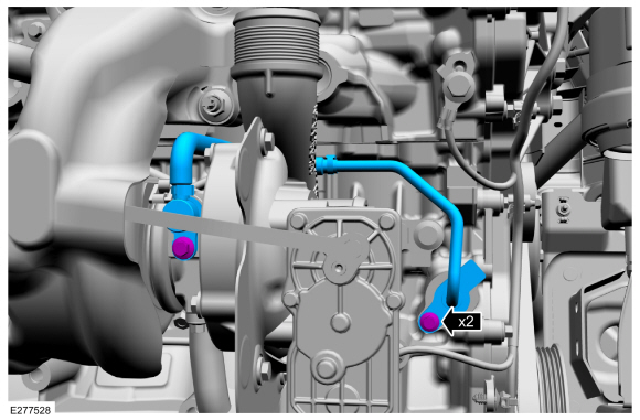
Remove the bolts, then remove and discard the
turbocharger oil supply tube.
 |
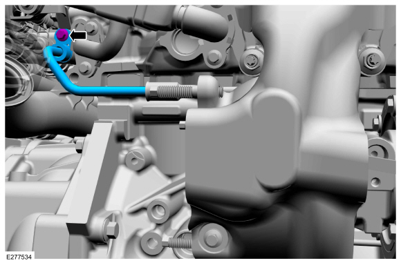
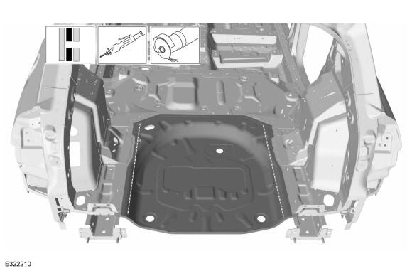
-
Remove the bolts, then remove and discard the turbocharger oil return tube.
 |
-
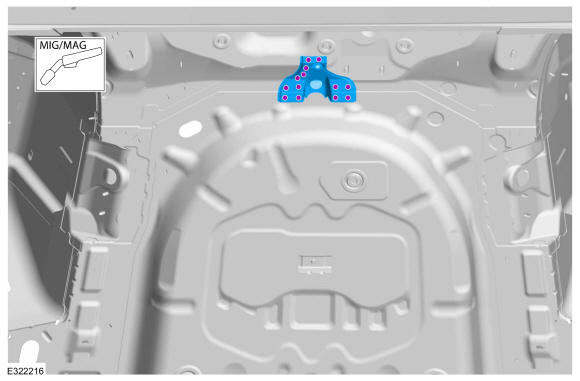
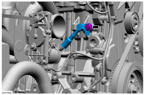
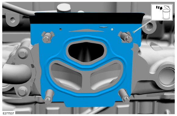
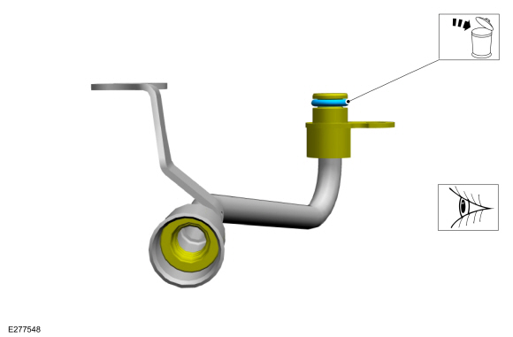
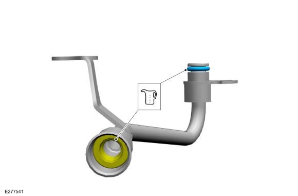
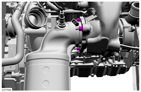
Remove the bolt, then remove the outer half of the turbocharger coolant return tube.
 |
-
-
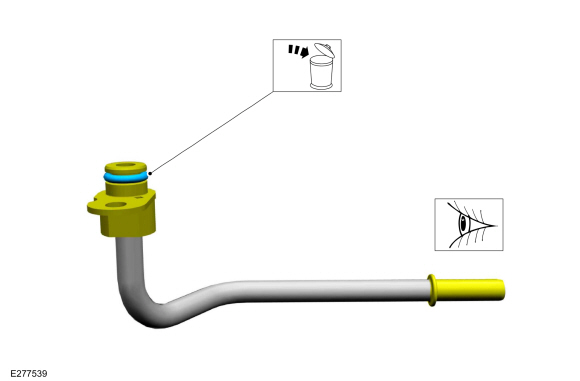
Remove and discard the turbocharger coolant tube O-ring seal.
Material: Motorcraft® Metal Brake Parts Cleaner / PM-4-A, PM-4-B, APM-4-C
-
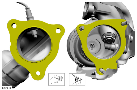
NOTICE: Do not use a metal brush, damage to sealing area will result in leaks.
Use brake cleaner and a nylon brush to clean. Clean the turbocharger coolant tube sealing surfaces. Inspect the sealing surfaces for debris or damage, make sure the retaining bracket is not bent, check for squareness of the O-ring area. Install new components if needed.
-
Remove and discard the turbocharger coolant tube O-ring seal.
 |
-
Remove the bolt, then remove the outer half of the turbocharger coolant supply tube.
 |
-
-
Remove and discard the turbocharger coolant tube O-ring seal.
-
NOTICE: Do not use a metal brush, damage to sealing area will result in leaks.
Use brake cleaner and a nylon brush to clean. Clean the turbocharger coolant tube sealing surfaces. Inspect the sealing surfaces for debris or damage, make sure the retaining bracket is not bent, check for squareness of the O-ring area. Inspect the rubber gasket. Install new components if needed.
Material: Motorcraft® Metal Brake Parts Cleaner / PM-4-A, PM-4-B, APM-4-C
-
Remove and discard the turbocharger coolant tube O-ring seal.
 |
-
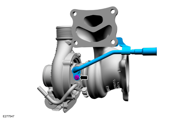
Disconnect the turbocharger electrical connector.
 |
-
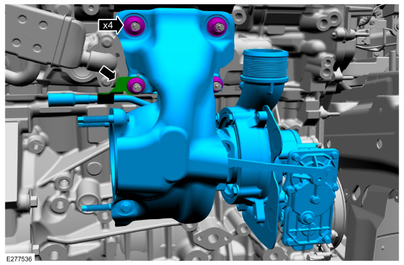
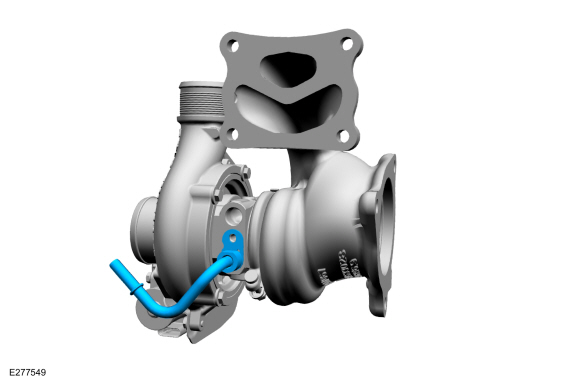
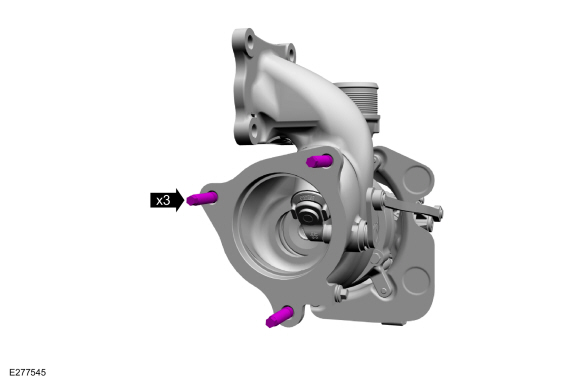
NOTE: The coolant tube bracket is retained by the left lower turbocharger stud and nut.
Remove the turbocharger mounting nuts, detach the coolant tube bracket, then remove the turbocharger.
 |
-
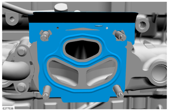
Remove and discard the turbocharger gasket.
 |
-
Remove the turbocharger mounting studs, if they need to be removed.
 |
-
Remove and discard the turbocharger exhaust flange studs.
 |
-
If needed, remove the turbocharger coolant tube bolt, then remove the turbocharger coolant return tube.
 |
-
-
NOTE: This sub-step is only needed if the component was removed.
Remove and discard the turbocharger coolant tube O-ring seal.
-
NOTICE: Do not use a metal brush, damage to sealing area will result in leaks.
NOTE: This sub-step is only needed if the component was removed.
Use brake cleaner and a nylon brush to clean. Clean the turbocharger coolant tube sealing surfaces. Inspect the sealing surfaces for debris or damage and make sure the retaining bracket is not bent, check for squareness of the O-ring area. Inspect the rubber gasket. Install new components if needed.
Material: Motorcraft® Metal Brake Parts Cleaner / PM-4-A, PM-4-B, APM-4-C
-
Inspect the rubber gasket. Install new components if needed.
-
 |
-
If needed, remove the turbocharger coolant supply tube.
 |
-
-
NOTE: This sub-step is only needed if the component was removed.
Remove and discard the turbocharger coolant tube O-ring seal.
-
NOTICE: Do not use a metal brush, damage to sealing area will result in leaks.
NOTE: This sub-step is only needed if the component was removed.
Use brake cleaner and a nylon brush to clean. Clean the turbocharger coolant tube sealing surfaces. Inspect the sealing surfaces for debris or damage, make sure the retaining bracket is not bent, check for squareness of the O-ring area. Install new components if needed.
Material: Motorcraft® Metal Brake Parts Cleaner / PM-4-A, PM-4-B, APM-4-C
-
Use brake cleaner and a nylon brush to clean.
Clean the turbocharger coolant tube gasket sealing surface. Install new
components if needed.
Material: Motorcraft® Metal Brake Parts Cleaner / PM-4-A, PM-4-B, APM-4-C
-
 |
Installation
All vehicles
-
-
NOTE: This sub-step is only needed if the component was removed.
Install a new turbocharger coolant tube O-ring seal.
-
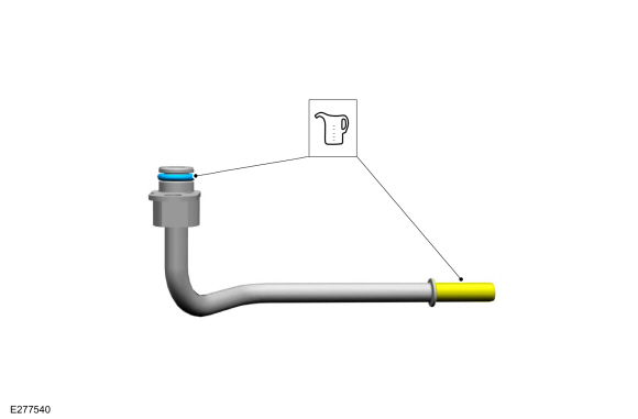
Lubricate the new O-ring seal and the tube sealing surface with clean engine coolant.
Refer to: Specifications (303-03A Engine Cooling - 2.0L EcoBoost (177kW/240PS) – MI4, Specifications).
-
 |
-
NOTICE: Do not use a metal brush, damage to sealing area will result in leaks.
NOTE: This step is only needed if the component was removed.
-
Carefully use a nylon brush to remove the old
O-ring residue, use brake cleaner to rinse the O-ring residue out of the
turbocharger tube O-ring bore. Inspect the area for deep scratches and
gouges. Install new components if needed.
Material: Motorcraft® Metal Brake Parts Cleaner / PM-4-A, PM-4-B, APM-4-C
-
If removed, fit the turbocharger coolant supply
tube to the turbocharger. The lower coolant supply tube goes into the
turbocharger first.
-
Carefully use a nylon brush to remove the old
O-ring residue, use brake cleaner to rinse the O-ring residue out of the
turbocharger tube O-ring bore. Inspect the area for deep scratches and
gouges. Install new components if needed.
|
-
-
NOTE: This sub-step is only needed if the component was removed.
If removed, install a new turbocharger coolant tube O-ring seal. Lubricate the turbocharger coolant tube O-ring seal with clean engine coolant.
Refer to: Specifications (303-03A Engine Cooling - 2.0L EcoBoost (177kW/240PS) – MI4, Specifications).
-
Lubricate the turbocharger coolant tube rubber gasket with clean engine coolant.
Refer to: Specifications (303-03A Engine Cooling - 2.0L EcoBoost (177kW/240PS) – MI4, Specifications).
-
 |
-
NOTICE: Do not use a metal brush, damage to sealing area will result in leaks.
NOTE: This step is only needed if the component was removed.
-
Carefully use a nylon brush to remove the old
O-ring residue, use brake cleaner to rinse the O-ring residue out of the
turbocharger tube O-ring bore. Inspect the area for deep scratches and
gouges. Install new components if needed.
Material: Motorcraft® Metal Brake Parts Cleaner / PM-4-A, PM-4-B, APM-4-C
-
If removed, fit the turbocharger coolant return
tube to the turbocharger. The lower coolant supply tube goes into the
turbocharger first.
-
If removed, install and tighten the turbocharger coolant tube bolt.
Torque: 97 lb.in (11 Nm)
-
Carefully use a nylon brush to remove the old
O-ring residue, use brake cleaner to rinse the O-ring residue out of the
turbocharger tube O-ring bore. Inspect the area for deep scratches and
gouges. Install new components if needed.
|
-
Install and tighten the turbocharger exhaust flange studs.
Torque: 30 lb.ft (40 Nm)
 |
-
If removed install and tighten the turbocharger mounting studs.
Torque: 159 lb.in (18 Nm)
|
-
Install the new turbocharger gasket.
 |
-
NOTE: The coolant tube bracket is retained by the left lower turbocharger stud and nut.
Install the turbocharger, attach the coolant tube bracket, then install and tighten the turbocharger mounting nuts.
Torque: 39 lb.ft (53 Nm)
|
-
Connect the turbocharger electrical connector.
|
-
Install a new turbocharger coolant tube O-ring seal.
Lubricate the turbocharger coolant tube O-ring seal and rubber gasket
with clean engine coolant.
Refer to: Specifications (303-03A Engine Cooling - 2.0L EcoBoost (177kW/240PS) – MI4, Specifications).
 |
-
-
NOTICE: Do not use a metal brush damage to sealing area will result in leaks.
Carefully use a nylon brush to remove the old O-ring residue, use brake cleaner to rinse the O-ring residue out of the turbocharger tube to engine O-ring bore. Inspect the area for deep scratches and gouges. Install new components if needed.
Material: Motorcraft® Metal Brake Parts Cleaner / PM-4-A, PM-4-B, APM-4-C
-
Install the outer half of the turbocharger
coolant supply tube, then install and tighten the turbocharger coolant
supply tube bolt.
Torque: 35 lb.ft (48 Nm)
-
|
-
Install a new turbocharger coolant tube O-ring seal.
Lubricate the new O-ring seal and the tube sealing surface with clean
engine coolant.
Refer to: Specifications (303-03A Engine Cooling - 2.0L EcoBoost (177kW/240PS) – MI4, Specifications).
 |
-
-
NOTICE: Do not use a metal brush damage to sealing area will result in leaks.
Carefully use a nylon brush to remove the old O-ring residue, use brake cleaner to rinse the O-ring residue out of the turbocharger tube to engine O-ring bore. Inspect the area for deep scratches and gouges. Install new components if needed.
Material: Motorcraft® Metal Brake Parts Cleaner / PM-4-A, PM-4-B, APM-4-C
-
Install the outer half of the turbocharger
coolant return tube, then install and tighten the turbocharger coolant
return tube bolt.
Torque: 97 lb.in (11 Nm)
-
|
-
NOTICE: Ensure that a new turbocharger oil return tube O-ring and gasket are used.
Install a new turbocharger oil return tube O-ring seal and a new turbocharger oil return tube gasket if not already installed. Lubricate the new turbocharger oil return tube O-ring seal with clean engine oil.
Refer to: Specifications (303-01A Engine - 2.0L EcoBoost (177kW/240PS) – MI4, Specifications).
 |
-
NOTICE: Do not use a metal brush, damage to sealing area will result in leaks.
NOTE: The oil return tube must be fully seated prior to fastener rundown.
-
Carefully use a nylon brush to remove the old
O-ring residue, use brake cleaner to rinse the O-ring residue out of the
turbocharger tube O-ring bore. Inspect the area for deep scratches and
gouges. Install new components if needed.
-
Install the turbocharger oil return tube, then
install and tighten the turbocharger oil return tube bolts.
Material: Motorcraft® Metal Brake Parts Cleaner / PM-4-A, PM-4-B, APM-4-C
Torque: 97 lb.in (11 Nm)
-
Carefully use a nylon brush to remove the old
O-ring residue, use brake cleaner to rinse the O-ring residue out of the
turbocharger tube O-ring bore. Inspect the area for deep scratches and
gouges. Install new components if needed.
 |
-
NOTICE: Do not reuse the turbocharger oil filter, a new turbocharger oil filter must be used.
NOTICE: Ensure that new turbocharger oil supply tube O-rings and gaskets are used.
Install the new turbocharger oil supply tube O-rings, gaskets and oil filter if not already installed. Lubricate the O-ring seals with clean engine oil.
Refer to: Specifications (303-01A Engine - 2.0L EcoBoost (177kW/240PS) – MI4, Specifications).
 |
-
NOTE: The oil supply tube must be fully seated prior to fastener tightening.
-
NOTICE: Do not use a metal brush, damage to sealing area will result in leaks.
Carefully use a nylon brush to remove the old O-ring residue, use brake cleaner to rinse the O-ring residue out of the turbocharger and engine O-ring bores. Inspect the area for deep scratches and gouges. Install new components if needed.
Material: Motorcraft® Metal Brake Parts Cleaner / PM-4-A, PM-4-B, APM-4-C
-
Install and fully seat the turbocharger oil supply tube, then install and tighten the bolts.
Torque: 97 lb.in (11 Nm)
-
 |
AWD (all-wheel drive) vehicles
-
Clean and Inspect the gasket surfaces.
 |
-
Install a new gasket.
 |
-
Install the catalytic converter, then install the new nuts finger tight at this stage.
 |
-
Tighten the catalytic converter nuts.
Torque: 30 lb.ft (40 Nm)
 |
-
Install the battery tray.
Refer to: Battery Tray - 2.0L EcoBoost (177kW/240PS) – MI4/2.3L EcoBoost (199kW/270PS) (414-01 Battery, Mounting and Cables, Removal and Installation).
FWD (front wheel drive) vehicles
-
Install the catalytic converter.
Refer to: Catalytic Converter (309-00A Exhaust System - 2.0L EcoBoost (177kW/240PS) – MI4, Removal and Installation).
Refer to: Catalytic Converter (309-00A Exhaust System - 2.0L EcoBoost (177kW/240PS) – MI4, Removal and Installation).
All vehicles
-
Install the lower air cleaner outlet pipe, then tighten the lower air cleaner outlet pipe clamp.
Torque: 44 lb.in (5 Nm)
|
-
Install the charge air cooler upper inlet pipe, then
tighten the clamp. Engage the charge air cooler upper intake pipe
retaining clip. Attach the harness retainer to the stud bolt, then
connect the turbocharger bypass valve electrical connector.
Torque: 44 lb.in (5 Nm)
|
-
Install the upper air cleaner outlet pipe.
Refer to: Air Cleaner Outlet Pipe (303-12A Intake Air Distribution and Filtering - 2.0L EcoBoost (177kW/240PS) – MI4, Removal and Installation).
FWD (front wheel drive) vehicles
-
Install the right front wheel and tire.
Refer to: Wheel and Tire (204-04A Wheels and Tires, Removal and Installation).
AWD (all-wheel drive) vehicles
-
Install the power transfer unit.
Refer to: Power Transfer Unit - Vehicles Without: Power Transfer Unit Oil-to-Coolant Cooler (307-07B Power Transfer Unit - 2.0L EcoBoost (177kW/240PS) – MI4, Installation).
Refer to: Power Transfer Unit - Vehicles With: Power Transfer Unit Oil-to-Coolant Cooler (307-07B Power Transfer Unit - 2.0L EcoBoost (177kW/240PS) – MI4, Installation).
All vehicles
-
Check the engine oil level and fill as needed.
Refer to: Specifications (303-01A Engine - 2.0L EcoBoost (177kW/240PS) – MI4, Specifications).
-
Fill the cooling system.
Refer to: Engine Cooling System Draining, Vacuum Filling and Bleeding (303-03A Engine Cooling - 2.0L EcoBoost (177kW/240PS) – MI4, General Procedures).
 Diagnosis and Testing - Turbocharger Controls
Diagnostic Trouble Code (DTC) Chart
Diagnostics in this manual assume a certain skill level and knowledge of Ford-specific diagnostic practices. REFER to: Diagnostic Methods (100-00 General Information, Description and Operation)...
 Removal and Installation - Turbocharger Coolant Return Tube
Removal and Installation
NOTICE:
The turbocharger compressor vanes can be damaged by even the
smallest particles. When removing any turbocharger or engine air intake
system component, ensure that no debris enters the system...
Other information:
Lincoln Corsair 2020-2026 Owners Manual: Trailer Sway Control. Recommended Towing Weights
Trailer Sway Control WARNING: Turning off trailer sway control increases the risk of loss of vehicle control, serious injury or death. Ford does not recommend disabling this feature except in situations where speed reduction may be detrimental (such as hill climbing), the driver has significant trailer towing experience, and can control trailer sway and maintain safe operation...
Lincoln Corsair 2020-2026 Service Manual: Removal and Installation - High-Pressure Fuel Pump Drive Unit
Removal Remove the valve cover. Refer to: Valve Cover (303-01A Engine - 2.0L EcoBoost (177kW/240PS) – MI4, Removal and Installation). Remove the high-pressure fuel pump drive unit bolts, then remove the high-pressure fuel pump drive unit...
Categories
- Manuals Home
- 1st Generation Lincoln Corsair Owners Manual
- 1st Generation Lincoln Corsair Service Manual
- General Procedures - Brake Service Mode Activation and Deactivation
- Auto-Start-Stop
- Opening and Closing the Hood
- New on site
- Most important about car
Creating a Vehicle Wi-Fi Hotspot
You can create a Wi-Fi hotspot in your vehicle and allow devices to connect to it for access to the Internet.
 Select the settings option on
the
feature bar.
Select the settings option on
the
feature bar.