Lincoln Corsair: Automatic Transmission - Automatic Transmission – HF45 / Removal and Installation - Roll Restrictor RH
Special Tool(s) /
General Equipment
Removal
-
With the vehicle in NEUTRAL, position it on a hoist.
Refer to: Roll Restrictor RH (307-01B Automatic Transmission - Automatic Transmission – HF45, Removal and Installation).
-
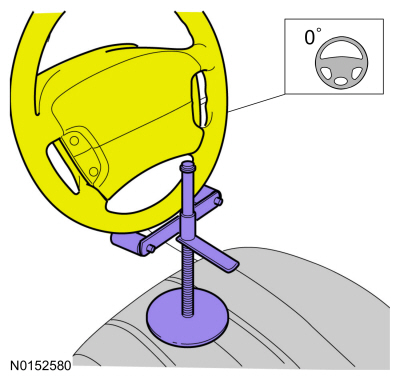
Using a holding device, hold the steering wheel in the straight-ahead position.
-
-
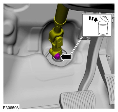
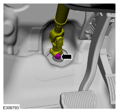
Remove the bolt and discard.
-
Position steering column shaft aside.
-
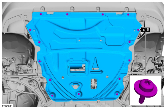
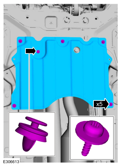
Remove the retainers and the underbody shield.
-
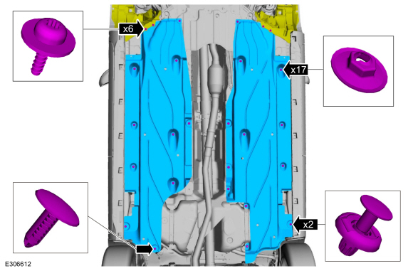
Remove the retainers and the underbody shields.
-
Remove the retainers and the underbody shield.
-
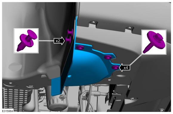
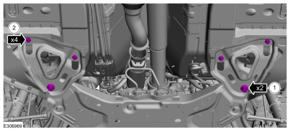
On both sides, remove the retainers and the front underbody shield.
-
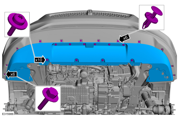
Remove the retainers and the front underbody shield.
-
Remove the nuts and the bracket.
-
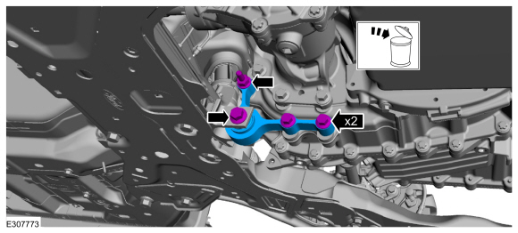
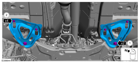
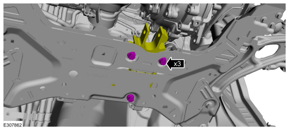
Remove and discard the roll restrictor bracket bolts and remove the bracket.
-
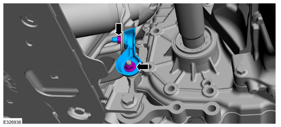
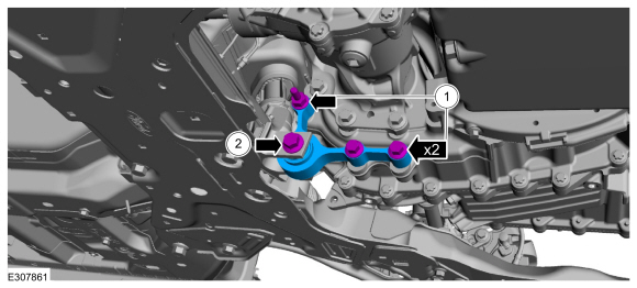
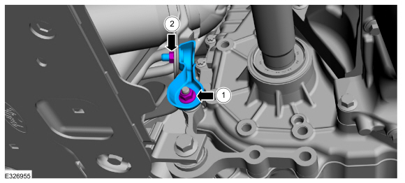
Remove and discard the roll restrictor bolts.
-
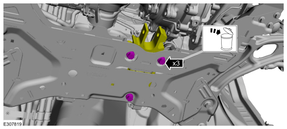
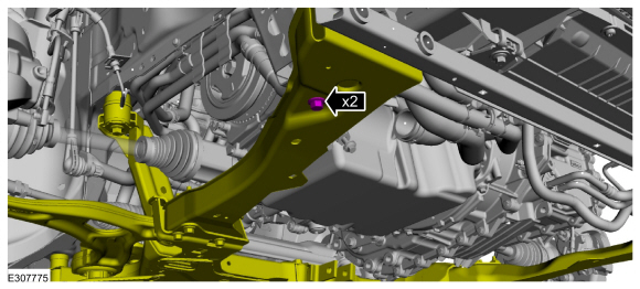
Remove the subframe support bracket bolts.
-
-
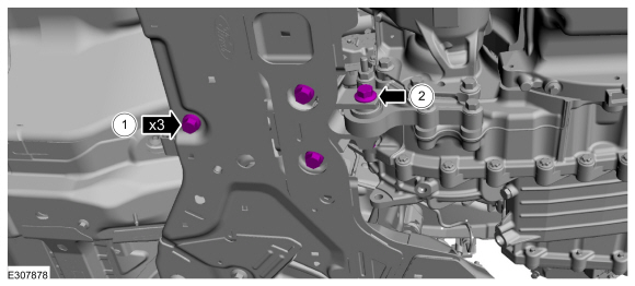
Remove and discard the rearward subframe bolts.
-
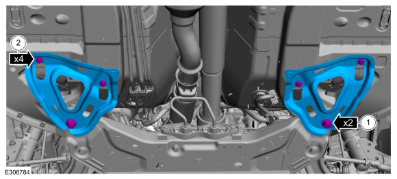
Remove the bolts and the subframe brackets.
-
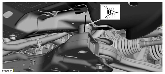
On both sides, index-mark the subframe to the body.
-
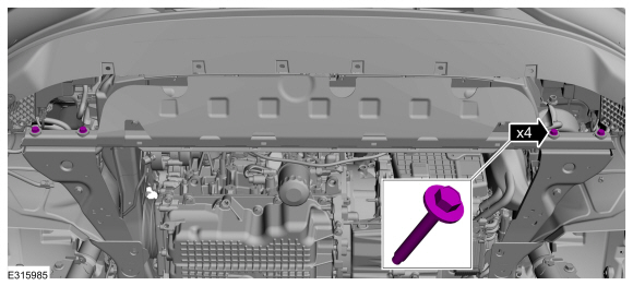
On both sides, remove the front subframe bolts.
-
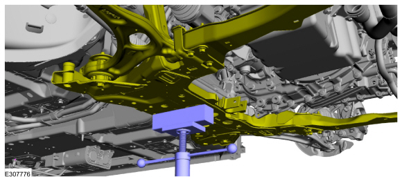
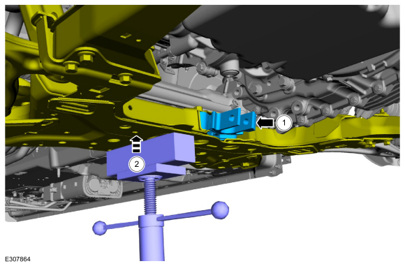
Support the subframe with a screw jack.
Use the General Equipment: Wooden Block
-
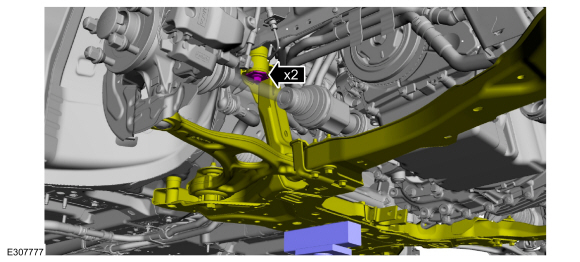
NOTE:
Do not remove the bolts.
On both sides, loosen the subframe bolts.
-
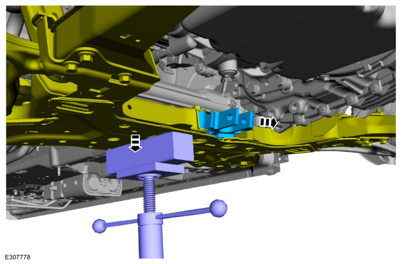
NOTE:
Lower the subframe far enough to remove the roll restrictor without interference from the transmission.
Using a screw jack, lower the subframe and remove the roll restrictor.
Use the General Equipment: Wooden Block
Installation
-
-
Install the roll restrictor.
-
Raise the subframe.
-
On both sides, install the front subframe bolts finger tight.
-
-
Install the subframe brackets and the new rearward subframe bolts finger tight.
-
Install the subframe bracket bolts finger tight.
-
On both sides, align index-mark made during removal.
-
On both sides, tighten the subframe bolts.
Torque:
85 lb.ft (115 Nm)
-
On both sides, tighten the front subframe bolts.
Torque:
85 lb.ft (115 Nm)
-
-
Tighten the subframe bolts in two stages.
Torque:
Stage 1:
159 lb.ft (215 Nm)
Stage 2:
60°
-
Tighten the subframe bracket bolts.
Torque:
46 lb.ft (63 Nm)
-
Install the subframe support bracket bolts.
Torque:
22 lb.ft (30 Nm)
-
Install new roll restrictor bolts finger tight.
-
-
Install the roll restrictor bracket, new bolts and studbolt.
Torque:
81 lb.ft (110 Nm)
-
Install a new roll restrictor bolt finger tight.
-
-
Tighten the roll restrictor bolts.
Torque:
52 lb.ft (70 Nm)
-
Tighten the roll restrictor bolt.
Torque:
129 lb.ft (175 Nm)
-
Install the bracket and the nuts.
Torque:
1:
35 lb.ft (47 Nm)
2:
18 lb.ft (25 Nm)
-
Install the retainers and the front underbody shield.
-
On both sides, install the retainers and the front fender air deflector.
-
Install the underbody shield and the retainers.
Torque:
22 lb.in (2.5 Nm)
-
Install the underbody shields and the retainers.
Torque:
22 lb.in (2.5 Nm)
-
Install the underbody shield and the retainers.
Torque:
13 lb.in (1.5 Nm)
-
Position steering column shaft and install a new bolt.
Torque:
46 lb.ft (63 Nm)
-
Remove the holding device.
Removal
To remove the ISC (inverter system controller).
Refer to: Inverter System Controller [SOBDMC] (303-14D Electric Powertrain Control, Removal and Installation)...
Special Tool(s) /
General Equipment
307-805Alignment Pins (2)
Ford Diagnostic Equipment
Removal
NOTE:
This step is only necessary when installing a new transmission or ISC (Inverter System Controller)...
Other information:
Regularly plug in your vehicle to get optimal
electric-only range capability from the high
voltage battery. Charging your vehicle adds
electrical energy. This energy propels the
vehicle.
Estimated electric-only driving range shows
in blue next to the gasoline range on the
information display...
Diagnostic Trouble Code (DTC) Chart
Diagnostics in this manual assume a certain skill level and knowledge of Ford-specific diagnostic practices. REFER to: Diagnostic Methods (100-00 General Information, Description and Operation).
Module
DTC
Description
Action
PCM
P0111:00
Intake Air Temperature Sensor 1 Circuit Range/Performance (Bank 1): No Sub Type Information
GO to Pinpoint ..

 Removal and Installation - Inverter System Controller
 Removal and Installation - Transmission