Lincoln Corsair: Engine - 2.0L EcoBoost (177kW/240PS) – MI4 / Removal and Installation - Oil Pump
Special Tool(s) /
General Equipment
 |
100-002
(TOOL-4201-C)
Holding Fixture with Dial Indicator Gauge |
 |
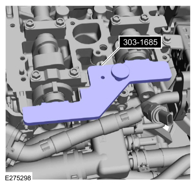
303-1685
Alignment Tool, Camshaft |
 |
303-1688
Preload Tool, Balance Shaft |
 |
303-507
Timing Peg, Crankshaft TDC
TKIT-2001N-FLM
TKIT-2001N-ROW |
Removal
-
Remove the oil pan.
Refer to: Oil Pan (303-01A Engine - 2.0L EcoBoost (177kW/240PS) – MI4, Removal and Installation).
-
Mark the balancer unit and shafts on the top for reference that the balancer unit is at TDC .
-
Remove the bolts and the oil screen and pickup tube.
-
Remove and discard the oil screen and pickup tube O-ring seal.
-
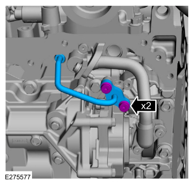
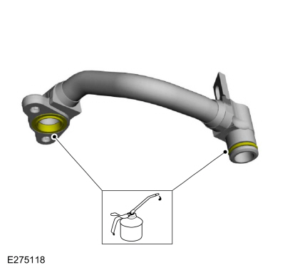
Remove the bolts and the oil outlet tube.
-
Inspect the oil outlet tube O-ring seal and replace if damaged.
-
-
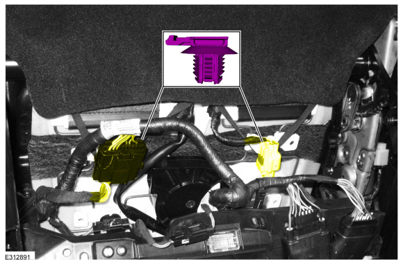
Remove the oil inlet tube-to-bracket bolt.
-
Remove the bolt and the oil inlet tube bracket.
-
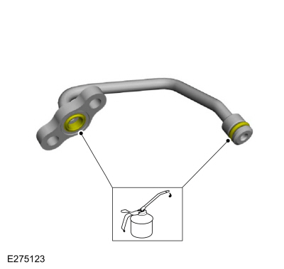
Remove the bolts and the oil inlet tube.
-
Inspect the oil inlet tube O-ring seal and replace if damaged.
-
NOTE:
Due to the precision interior construction of the balancer unit, it should not be disassembled.
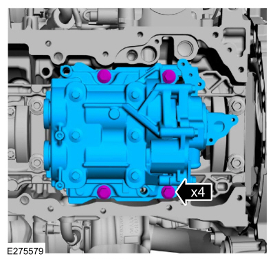
Remove the bolts and the balance unit.
-
Remove the adjustment shims from the seat faces of the balancer unit.
Installation
-
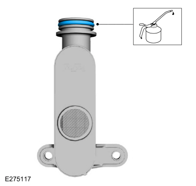
Prime the oil pump. Add 2 tablespoons of clean engine oil to the oil pump and rotate the oil pump by hand.
Refer to: Specifications (303-01A Engine - 2.0L EcoBoost (177kW/240PS) – MI4, Specifications).
-
Install the master adjustment shims (No. 50) on the seat faces of the balancer unit.
-
With the balancer unit shaft marks at the TDC
position, slowly install the balancer unit to the cylinder block to
avoid interference between the crankshaft drive gear and the balancer
unit driven gear.
-
Install the bolts and tighten in sequence shown.
Torque:
Stage 1:
27 lb.ft (36 Nm)
Stage 2:
60°
-
Loosen the bolts.
-
Tighten the bolts in sequence shown.
Torque:
Stage 1:
133 lb.in (15 Nm)
Stage 2:
45°
-
Remove Special Service Tool: 303-507
Timing Peg, Crankshaft TDC.
-
NOTE:
Once the special tool is removed the valves will go
into a neutral position and crankshaft and pistons can now freely be
rotated.
Remove Special Service Tool: 303-1685
Alignment Tool, Camshaft.
-
NOTICE:
Do not remove the spark plugs when the engine is hot
or cold soaked. Spark plug thread or cylinder head damage can occur.
Make sure that the engine is warm (hand touch after cooling down) prior
to spark plug removal.
NOTICE:
If a spark plug is dropped, internal damage may
result and the spark plug must be discarded. The use of a damaged spark
plug may cause cylinder misfire resulting in engine damage.
-
Use compressed air to remove any foreign material in the spark plug well before removing the spark plugs.
-
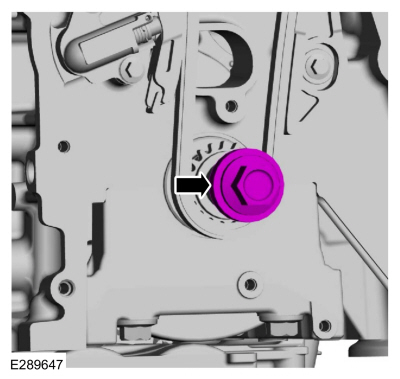
Install the crankshaft pulley bolt and rotate the
crankshaft to confirm that there are no meshing problems between the
balancer unit gear and the crankshaft gear.
-
Install the special tool and rotate the crankshaft
slowly clockwise until the crankshaft balance weight is up against the
Crankshaft TDC Timing Peg. The engine is now at TDC .
Use Special Service Tool: 303-507
Timing Peg, Crankshaft TDC.
-
Remove Special Service Tool: 303-507
Timing Peg, Crankshaft TDC.
 |
|
-
NOTE:
Measure the backlash and verify that it is within
specified range at all of the following 6 positions: 10 degrees, 30
degrees, 100 degrees, 190 degrees, 210 degrees and 280 degrees. It will
be necessary to reset the measuring equipment between measurements.
NOTE:
The measurement must be taken with the Dial
Indicator Gauge with Holding Fixture, a 5-mm Allen wrench and worm clamp
set up as shown. Mark the Allen wrench with a file 20 mm (0.79 in)
above the driven gear top surface. Make sure the worm clamp and Allen
wrench are not touching the balance shaft housing.
-
Mark the Allen wrench with a file 20 mm (0.79 in) above the driven gear top surface.
-
Install the balance shaft preload tool and bolts as shown.
Use Special Service Tool: 303-1688
Preload Tool, Balance Shaft.
-
Install and position the dial indicator gauge with
holding fixture on the Allen wrench 20 mm (0.79 in) as shown.
Use Special Service Tool: 100-002
(TOOL-4201-C)
Holding Fixture with Dial Indicator Gauge.
-
Rotate the crankshaft clockwise and measure the
backlash at all of the following 6 positions: 10 degrees, 30 degrees,
100 degrees, 190 degrees, 210 degrees and 280 degrees.
 |
|
-
Using the backlash measurement, select the proper shims from the Adjustment Shim Selection Table.
-
Backlash
-
Selection shim (No.)
-
Shim thickness
-
Remove the bolts and the balance unit.
-
Remove the master adjustment shims (No. 50) from the balancer unit.
-
Install the selected adjustment shims on the seat faces of the balancer unit.
-
Install the special tool and rotate the crankshaft
slowly clockwise until the crankshaft balance weight is up against the
Crankshaft TDC Timing Peg. The engine is now at TDC .
Use Special Service Tool: 303-507
Timing Peg, Crankshaft TDC.
-
With the balancer unit shaft marks at the TDC
position, slowly install the balancer unit to the cylinder block to
avoid interference between the crankshaft drive gear and the balancer
unit driven gear.
-
Install the bolts and tighten in sequence shown.
Torque:
Stage 1:
133 lb.in (15 Nm)
Stage 2:
45°
-
Remove Special Service Tool: 303-507
Timing Peg, Crankshaft TDC.
|
|
-
NOTE:
Measure the backlash and verify that it is within
specified range at all of the following 6 positions: 10 degrees, 30
degrees, 100 degrees, 190 degrees, 210 degrees and 280 degrees. It will
be necessary to reset the measuring equipment between measurements.
NOTE:
The measurement must be taken with the Dial
Indicator Gauge with Holding Fixture, a 5-mm Allen wrench and worm clamp
set up as shown. Mark the Allen wrench with a file 20 mm (0.79 in)
above the driven gear top surface. Make sure the worm clamp and Allen
wrench are not touching the balance shaft housing.
-
Mark the Allen wrench with a file 20 mm (0.79 in) above the driven gear top surface.
-
Install the balance shaft preload tool and bolts as shown.
Use Special Service Tool: 303-1688
Preload Tool, Balance Shaft.
-
Install and position the dial indicator gauge with
holding fixture on the Allen wrench 20 mm (0.79 in) as shown.
Use Special Service Tool: 100-002
(TOOL-4201-C)
Holding Fixture with Dial Indicator Gauge.
-
Rotate the crankshaft clockwise and measure the
backlash at all of the following 6 positions: 10 degrees, 30 degrees,
100 degrees, 190 degrees, 210 degrees and 280 degrees.
-
If the backlash exceeds the specified range of 0.040
to 0.140 mm (0.00157 to 0.0055 in), install a new balancer unit and
repeat the procedure.
-
After the special tools are removed, remove the worm clamp and Allen wrench.
Remove Special Service Tool: 100-002
(TOOL-4201-C)
Holding Fixture with Dial Indicator Gauge.
, 303-1688
Preload Tool, Balance Shaft.
|
|
-
Lubricate the oil inlet tube O-ring seal with clean engine oil.
Refer to: Specifications (303-01A Engine - 2.0L EcoBoost (177kW/240PS) – MI4, Specifications).
-
-
Install the oil inlet tube and the bolts.
Torque:
97 lb.in (11 Nm)
-
Install the oil inlet tube bracket and the bolt.
Torque:
97 lb.in (11 Nm)
-
Install the oil inlet tube-to-bracket bolt.
Torque:
97 lb.in (11 Nm)
-
Lubricate the oil outlet tube O-ring seals with clean engine oil.
Refer to: Specifications (303-01A Engine - 2.0L EcoBoost (177kW/240PS) – MI4, Specifications).
-
Install the oil outlet tube and the bolts.
Torque:
97 lb.in (11 Nm)
-
Install a new O-ring seal and lubricate with clean engine oil.
Refer to: Specifications (303-01A Engine - 2.0L EcoBoost (177kW/240PS) – MI4, Specifications).
-
Install the oil screen and pickup tube and the bolts.
Torque:
97 lb.in (11 Nm)
-
NOTICE:
If a spark plug is dropped, internal damage may
result and the spark plug must be discarded. The use of a damaged spark
plug may cause cylinder misfire resulting in engine damage.
Install the spark plugs.
Torque:
106 lb.in (12 Nm)
-
Install the special tool and rotate the crankshaft
slowly clockwise until the crankshaft balance weight is up against the
Crankshaft TDC Timing Peg. The engine is now at TDC .
Use Special Service Tool: 303-507
Timing Peg, Crankshaft TDC.
-
NOTICE:
The Camshaft Alignment Tool is for camshaft
alignment only. Using this tool to prevent engine rotation can result in
engine damage.
NOTE:
The camshaft timing slots are offset. If the
Camshaft Alignment Tool cannot be installed, remove the TDC Timing Peg
and rotate the crankshaft three-fourths of a revolution clockwise and
repeat the previous step of this procedure.
Install Special Service Tool: 303-1685
Alignment Tool, Camshaft.
-
Remove the crankshaft pulley bolt.
-
Install the oil pan.
Refer to: Oil Pan (303-01A Engine - 2.0L EcoBoost (177kW/240PS) – MI4, Removal and Installation).
Removal
NOTICE:
Do not loosen or remove the crankshaft pulley bolt without
first installing the special tools as instructed in this procedure. The
crankshaft pulley and the crankshaft timing sprocket are not keyed to
the crankshaft...
Other information:
Starting System
The starting system controls the cranking of the engine. The PCM
energizes the starter relay when it receives inputs from the ignition
switch, automatic transmission, and the BCM . When the starter relay is
energized, it applies power to the starter motor which cranks the
engine...
Removal
Remove the liftgate trim panel.
Refer to: Liftgate Trim Panel (501-05 Interior Trim and Ornamentation, Removal and Installation).
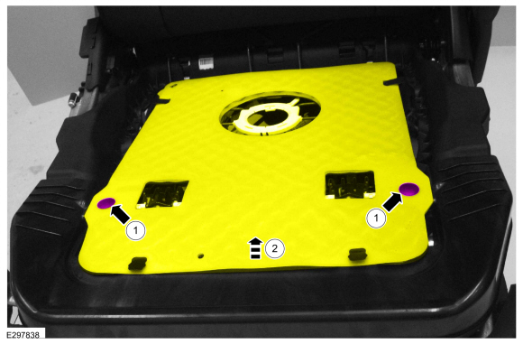
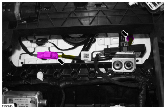
Remove the keyless entry rear antenna.
Disconnect the keyless entry rear antenna electrical connector...

 Removal and Installation - Timing Chain