Lincoln Corsair: Engine - 2.0L EcoBoost (177kW/240PS) – MI4 / Removal and Installation - Oil Pan
Special Tool(s) /
General Equipment
 |
303-290B-20
Adapter, Car-Bar
TKIT-2014D-ROW3
TKIT-2014D-FL_ROW |
 |
303-F070
Support Bar, Engine
TKIT-1999A-F/LT
TKIT-1999A-FM/FLM |
 |
303-F072
Support Bar, Engine |
| Oil Drain Equipment |
| Trolley Jack |
| Wooden Block |
Materials
| Name |
Specification |
Motorcraft® High Performance Engine RTV Silicone
TA-357 |
WSE-M4G323-A6
|
Removal
-
With the vehicle in NEUTRAL, position it on a hoist.
Refer to: Jacking and Lifting - Overview (100-02 Jacking and Lifting, Description and Operation).
-
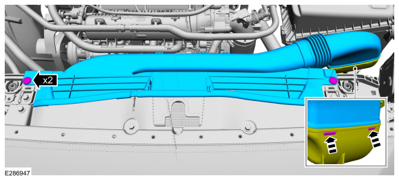
Remove the cowl panel grille.
Refer to: Cowl Panel Grille (501-02 Front End Body Panels, Removal and Installation).
-
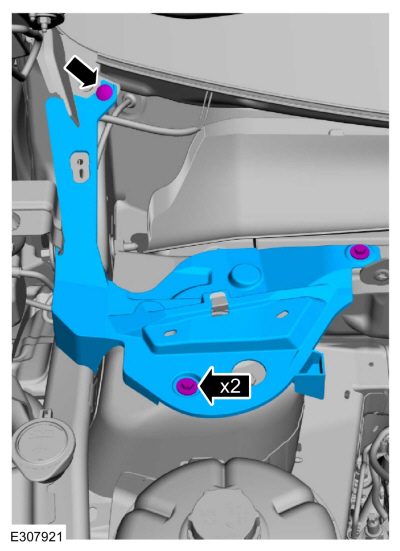
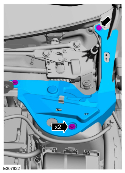
Remove the bolts, pin-type retainer and the RH cowl cover.
-
If equipped, remove the pin-type retainers and the RH fender trim cover.
-
-
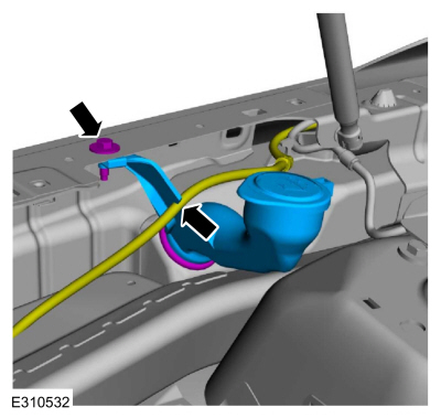
Remove the bolt and the washer bottle filler tube.
-
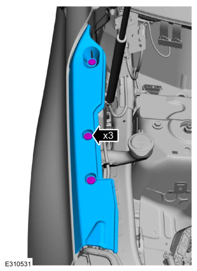
Remove the bolts, pin-type retainer and the LH cowl cover.
-
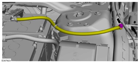
Remove the bolt and position the ground cable aside.
-
Remove the engine front cover.
Refer to: Engine Front Cover (303-01A Engine - 2.0L EcoBoost (177kW/240PS) – MI4, Removal and Installation).
-
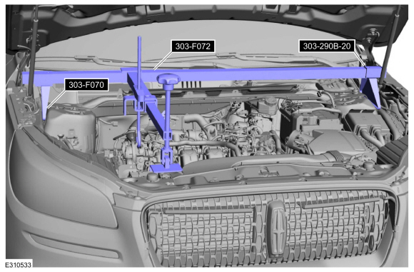
-
Using the feet from 303-F070 and the car bar
adapters 303-290B-20 assemble them on the 303-F072 engine support bar.
Install Special Service Tool: 303-F070
Support Bar, Engine.
, 303-290B-20
Adapter, Car-Bar.
, 303-F072
Support Bar, Engine.
-
Using the special tools, support the engine.
-
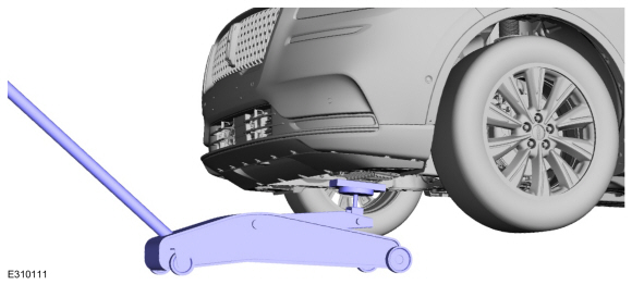
Remove the jack and wooden block.
Use the General Equipment: Trolley Jack
Use the General Equipment: Wooden Block
-
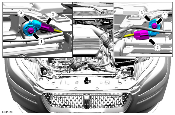
-
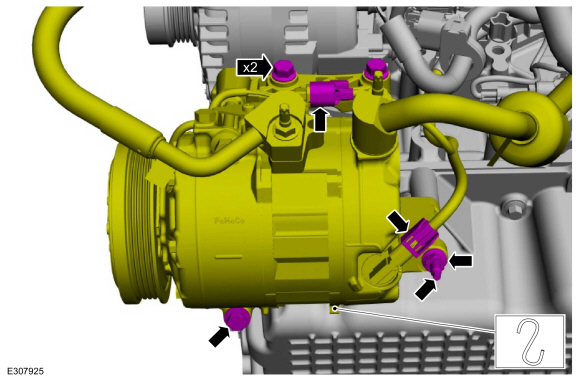
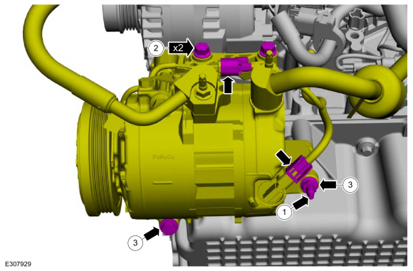
Disconnect the electrical connectors.
-
Remove the A/C compressor bolt.
-
Remove the A/C compressor bracket bolts and position the A/C compressor aside and support.
-
-
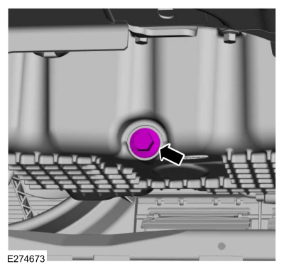
Remove the oil pan drain bolt and drain the engine oil.
Use the General Equipment: Oil Drain Equipment
-
Install the oil pan drain bolt.
Torque:
20 lb.ft (27 Nm)
-
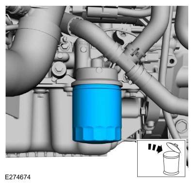
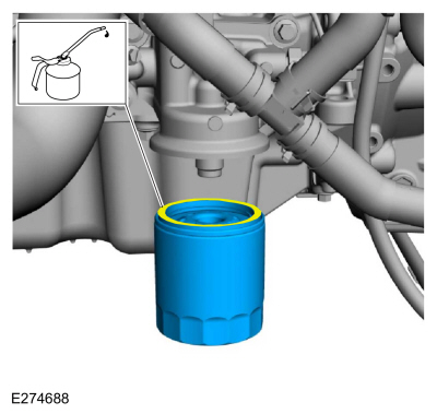
Remove and discard the engine oil filter.
Use the General Equipment: Oil Drain Equipment
-
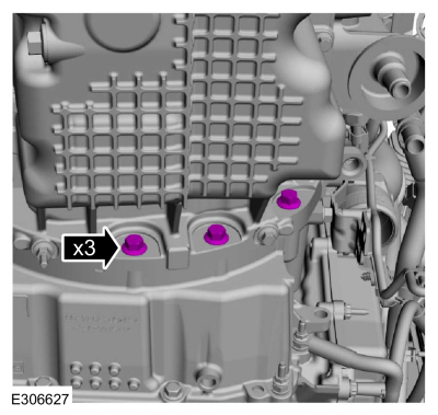
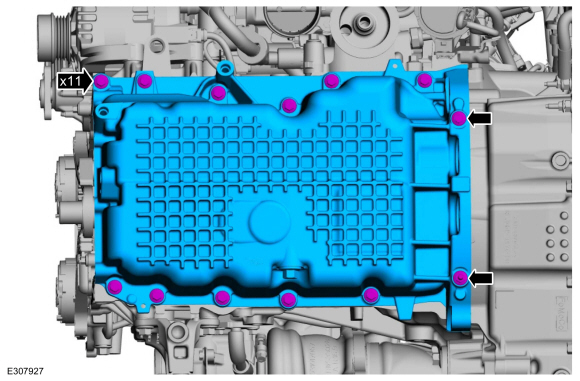
Remove the oil pan-to-transmission bolt.
-
Remove the oil pan-to-transmission bolts.
-
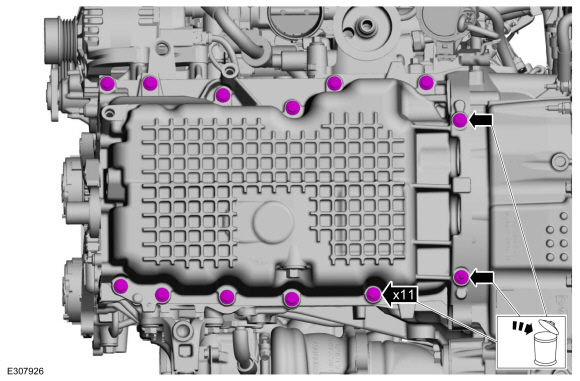
Remove and discard the oil pan bolts.
-
NOTICE:
Do not strike the oil pan sideways to remove, the
oil pan is doweled and will damage the oil pan and engine block.
Using the pry pads, remove the oil pan.
-
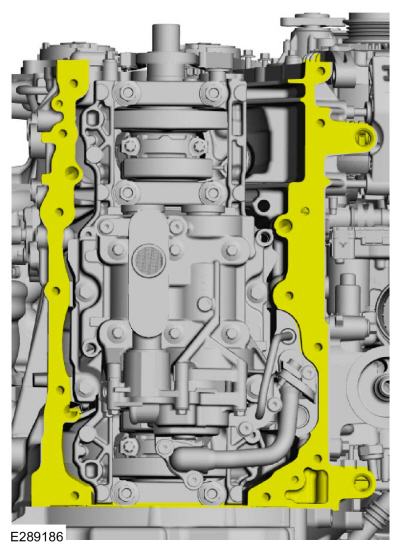
Clean and prepare the RTV sealing surface.
Refer to: RTV Sealing Surface Cleaning and Preparation (303-00 Engine System - General Information, General Procedures).
-
Clean and prepare the RTV sealing surface.
Refer to: RTV Sealing Surface Cleaning and Preparation (303-00 Engine System - General Information, General Procedures).
Installation
-
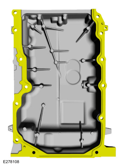
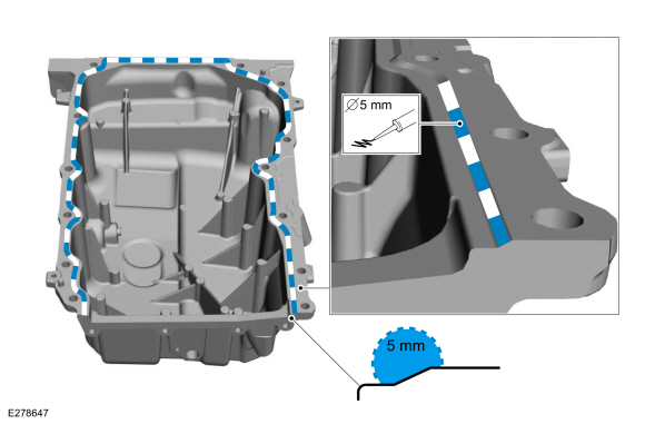
NOTE:
If the oil pan is not secured within 10 minutes of
silicone sealant application, the silicone sealant must be removed and
the sealing area cleaned. Allow to dry until there is no sign of
wetness, or 10 minutes, whichever is longer. Failure to follow this
procedure can cause future oil leakage.
Apply a 5 mm (0.19 in) bead of silicone sealant on the chamfer, as shown.
Material: Motorcraft® High Performance Engine RTV Silicone
/ TA-357
(WSE-M4G323-A6)
-
Install the oil pan and the new bolts finger-tight.
-
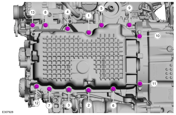
Tighten the bolts in sequence shown.
Torque:
18 lb.ft (25 Nm)
-
Install the oil pan-to-transmission bolt.
Torque:
35 lb.ft (48 Nm)
-
Install the oil pan bolts.
Torque:
35 lb.ft (48 Nm)
-
Lubricate the oil filter seal with clean engine oil and install.
Torque:
Stage 1:
71 lb.in (8 Nm)
Stage 2:
180°
-
-
Position the A/C compressor and install the stud.
Torque:
80 lb.in (9 Nm)
-
Install the A/C compressor bracket bolts.
Torque:
18 lb.ft (25 Nm)
-
Install the A/C compressor bolt and nut.
Torque:
18 lb.ft (25 Nm)
-
Connect the electrical connectors.
-
Install the jack and wooden block.
Use the General Equipment: Trolley Jack
Use the General Equipment: Wooden Block
-
Remove the special tools.
Remove Special Service Tool: 303-F070
Support Bar, Engine.
, 303-290B-20
Adapter, Car-Bar.
, 303-F072
Support Bar, Engine.
-
Install the engine front cover.
Refer to: Engine Front Cover (303-01A Engine - 2.0L EcoBoost (177kW/240PS) – MI4, Removal and Installation).
-
Position the ground cable and install the bolt.
Torque:
26 lb.ft (35 Nm)
-
Install the LH cowl cover, bolts and the pin-type retainer.
Torque:
22 lb.in (2.5 Nm)
-
-
Install the washer bottle filler tube and the bolt.
Torque:
13 lb.in (1.5 Nm)
-
If equipped, install the RH fender trim cover and the pin-type retainers.
-
Install the RH cowl cover, bolts and the pin-type retainer.
Torque:
22 lb.in (2.5 Nm)
-
Install the cowl panel grille.
Refer to: Cowl Panel Grille (501-02 Front End Body Panels, Removal and Installation).
-
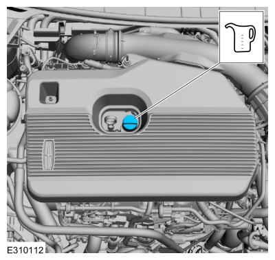
Fill the engine with clean engine oil.
Refer to: Specifications (303-01A Engine - 2.0L EcoBoost (177kW/240PS) – MI4, Specifications).
Removal
NOTICE:
The turbocharger compressor vanes can be damaged by even the
smallest particles. When removing any turbocharger or engine air intake
system component, ensure that no debris enters the system...
Special Tool(s) /
General Equipment
100-002
(TOOL-4201-C)
Holding Fixture with Dial Indicator Gauge
303-1685Alignment Tool, Camshaft
303-1688Preload Tool, Balance Shaft
303-507Timing Peg, Crankshaft TDCTKIT-2001N-FLMTKIT-2001N-ROW
Removal
Remove the oil pan...
Other information:
Diagnostic Trouble Code (DTC) Chart
Diagnostics in this manual assume a certain skill level and knowledge of Ford-specific diagnostic practices. REFER to: Diagnostic Methods (100-00 General Information, Description and Operation).
Module
DTC
Description
Action
PCM
P0034:00
Turbocharger/Supercharger Bypass Valve 'A' Control Circuit Low: No Sub Type Information
GO to Pinpoint Test..
Special Tool(s) /
General Equipment
100-002
(TOOL-4201-C)
Holding Fixture with Dial Indicator Gauge
205-153
(T80T-4000-W)
Handle
205-199
(T83T-3132-A1)
Installer, Spindle/Axle ShaftT83-4000-ATKIT-1983-FTKIT-1983-FLMTKIT-1983-FX
307-003
(T57L-500-B)
Holding Fixture, Transmission
307-091Handle, Torque ConverterTKIT-2009TC-F
307-300Gauge Bar, Shim Sel..
 Removal and Installation - Intake Manifold
 Removal and Installation - Oil Pump