Lincoln Corsair: Electronic Engine Controls - 2.0L EcoBoost (177kW/240PS) – MI4 / Removal and Installation - Knock Sensor (KS)
Materials
| Name | Specification |
|---|---|
| Motorcraft® Silicone Brake Caliper Grease and Dielectric Compound XG-3-A |
ESA-M1C200-A ESE-M1C171-A |
Removal
NOTE: Removal steps in this procedure may contain installation details.
-
NOTICE: Do not pull the engine appearance cover forward or sideways to remove. Failure to press straight upward on the underside of the cover at the attachment points may result in damage to the cover or engine components.
-
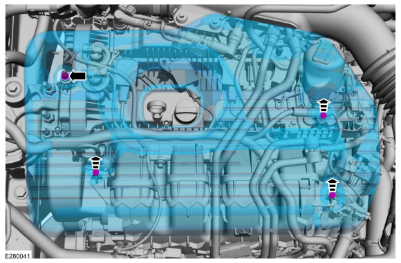
Remove the engine appearance cover nut.
-
Place your hand under the engine appearance cover at
each grommet location and pull straight up to release each grommet from
the studs.
-
After all of the grommets have been released from the studs, remove the appearance cover from the engine.
-
Remove the engine appearance cover nut.
 |
-
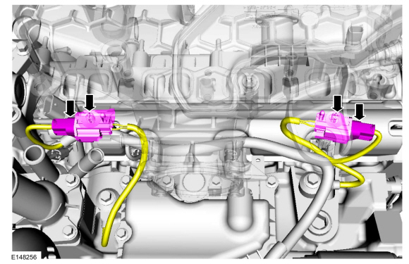
Disconnect the KS and release the connectors from the intake manifold.
 |
-
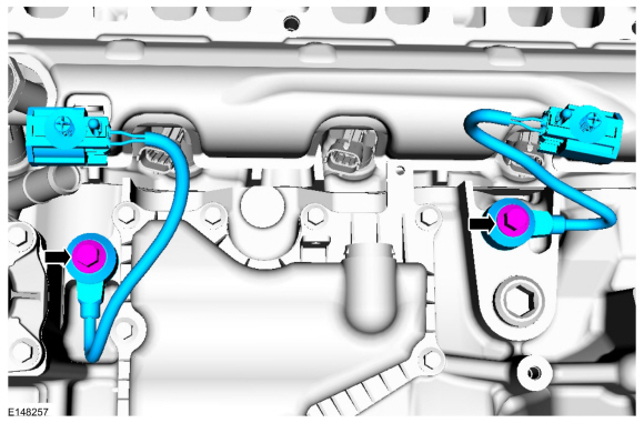
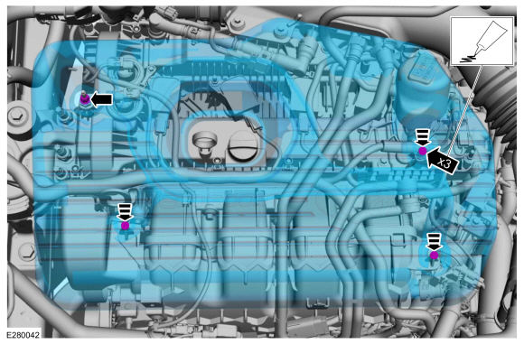
NOTE: Note the position of the components before removal.
Remove the KS .
Torque: 18 lb.ft (25 Nm)
 |
Installation
-
NOTE: Make sure that the components are installed to the position noted before removal.
To install, reverse the removal procedure.
-
-
NOTE: Lubricating the grommets with silicone grease will aid in the installation of the engine appearance cover, and any future removal and installation of the cover.
Lubricate each grommet with silicone grease.
Material: Motorcraft® Silicone Brake Caliper Grease and Dielectric Compound / XG-3-A (ESA-M1C200-A) (ESE-M1C171-A)
-
Position the engine appearance cover onto engine with the grommets aligned with the studs.
-
Press down on the engine appearance cover at each grommet location to attach the grommets onto the studs.
-
Install the engine appearance cover nut.
Torque: 44 lb.in (5 Nm)
-
If the engine appearance cover stud bolt is loosened
or removed, it must be installed/tightened into the valve cover.
Torque: 62 lb.in (7 Nm)
-
 |
 Removal and Installation - Intake Air Temperature (IAT) Sensor
Removal
NOTE:
Removal steps in this procedure may contain installation details.
Disconnect the IAT electrical connector.
Remove the IAT sensor...
 Removal and Installation - Manifold Absolute Pressure and Temperature (MAPT) Sensor
Materials
Name
Specification
Motorcraft® Silicone Brake Caliper Grease and Dielectric CompoundXG-3-A
ESA-M1C200-AESE-M1C171-A
Removal
NOTE:
Removal steps in this procedure may contain installation details...
Other information:
Lincoln Corsair 2020-2024 Service Manual: Description and Operation - Parking Brake - System Operation and Component Description
System Operation System Diagram Item Description 1 ABS module 2 LH parking brake actuator motor 3 GWM 4 RCM 5 PCM 6 BCM 7 IPC 8 Parking brake control switch 9 RH parking brake actuator motor Network Message Chart ABS Module Electronic Parking Brake Network Input Me..
Lincoln Corsair 2020-2024 Owners Manual: Under Hood Overview - 2.0L/2.3L
Windshield washer fluid reservoir. See Washer Fluid Check A. Engine coolant reservoir. See Engine Coolant Check. Engine oil dipstick. See Engine Oil Dipstick. Engine oil filler cap. See Engine Oil Check D. Brake fluid reservoir. See Brake Fluid Check. Battery. See Changing the 12V Battery. Power distribution box. See Fuse Specification Chart. Air filter assembly. See Changing the Engine ..
Categories
- Manuals Home
- 1st Generation Lincoln Corsair Owners Manual
- 1st Generation Lincoln Corsair Service Manual
- Auto Hold (IF EQUIPPED)
- Interior Lamps
- Opening and Closing the Hood
- New on site
- Most important about car
360 Degree Camera Cameras
Locating the Rear View Camera

The rear view camera is on the tailgate.
Locating the Front View Camera