Lincoln Corsair: Electronic Engine Controls - 2.0L EcoBoost (177kW/240PS) – MI4 / Removal and Installation - Manifold Absolute Pressure and Temperature (MAPT) Sensor
Materials
| Name | Specification |
|---|---|
| Motorcraft® Silicone Brake Caliper Grease and Dielectric Compound XG-3-A |
ESA-M1C200-A ESE-M1C171-A |
Removal
NOTE: Removal steps in this procedure may contain installation details.
-
NOTICE: Do not pull the engine appearance cover forward or sideways to remove. Failure to press straight upward on the underside of the cover at the attachment points may result in damage to the cover or engine components.
-
Remove the engine appearance cover nut.
-
Place your hand under the engine appearance cover at
each grommet location and pull straight up to release each grommet from
the studs.
-
After all of the grommets have been released from the studs, remove the appearance cover from the engine.
-
Remove the engine appearance cover nut.
 |
-
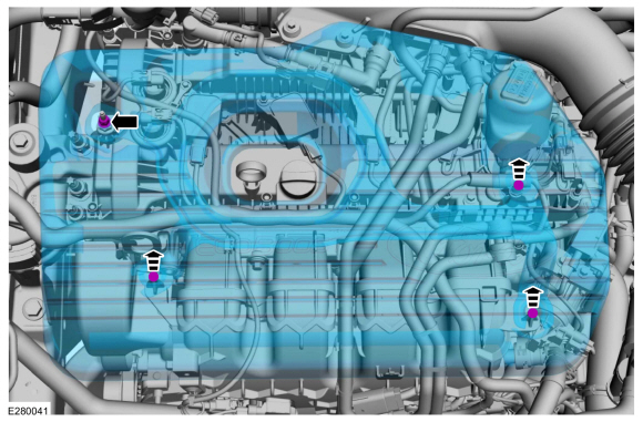
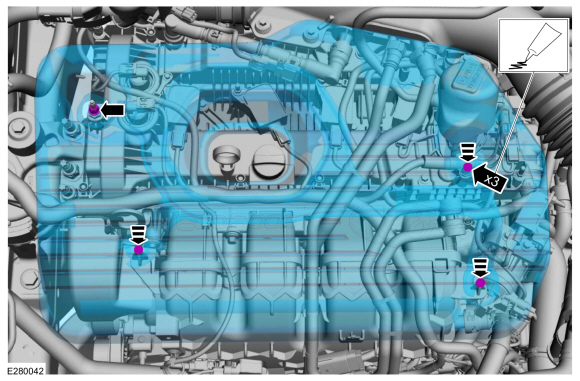
Disconnect the electrical connector. Remove the retainer and the MAPT sensor.
Torque: 55 lb.in (6.2 Nm)
 |
Installation
-
To install, reverse the removal procedure.
-
-
NOTE: Lubricating the grommets with silicone grease will aid in the installation of the engine appearance cover, and any future removal and installation of the cover.
Lubricate each grommet with silicone grease.
Material: Motorcraft® Silicone Brake Caliper Grease and Dielectric Compound / XG-3-A (ESA-M1C200-A) (ESE-M1C171-A)
-
Position the engine appearance cover onto engine with the grommets aligned with the studs.
-
Press down on the engine appearance cover at each grommet location to attach the grommets onto the studs.
-
Install the engine appearance cover nut.
Torque: 44 lb.in (5 Nm)
-
If the engine appearance cover stud bolt is loosened
or removed, it must be installed/tightened into the valve cover.
Torque: 62 lb.in (7 Nm)
-
 |
 Removal and Installation - Knock Sensor (KS)
Materials
Name
Specification
Motorcraft® Silicone Brake Caliper Grease and Dielectric CompoundXG-3-A
ESA-M1C200-AESE-M1C171-A
Removal
NOTE:
Removal steps in this procedure may contain installation details...
 Removal and Installation - Oil Pressure Control Solenoid
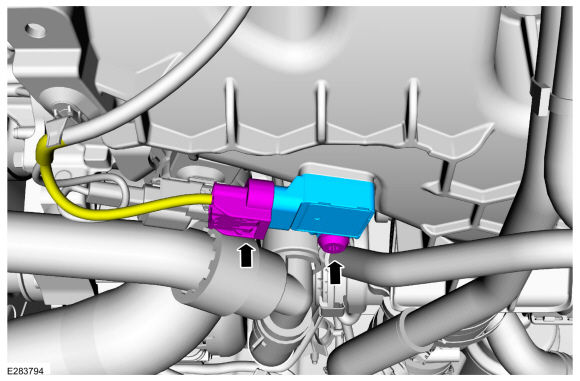
Removal
NOTE:
Removal steps in this procedure may contain installation details.
With the vehicle in NEUTRAL, position it on a hoist.
Refer to: Jacking and Lifting - Overview (100-02 Jacking and Lifting, Description and Operation)...
Other information:
Lincoln Corsair 2020-2024 Owners Manual: Waxing
Regular waxing is necessary to protect your car's paint from the elements. We recommend that you wash and wax the painted surface once or twice a year. When washing and waxing, park your vehicle in a shaded area out of direct sunlight. Always wash your vehicle before applying wax...
Lincoln Corsair 2020-2024 Service Manual: Removal and Installation - Occupant Classification System (OCS) Sensor - Vehicles With: Multi-Contour Seats
Special Tool(s) / General Equipment Flat Headed Screw Driver Removal WARNING: The following procedure prescribes critical repair steps required for correct restraint system operation during a crash. Follow all notes and steps carefully...
Categories
- Manuals Home
- 1st Generation Lincoln Corsair Owners Manual
- 1st Generation Lincoln Corsair Service Manual
- Normal Scheduled Maintenance
- Child Safety Locks
- Selecting a Drive Mode. DRIVE MODES
- New on site
- Most important about car
Keyless Starting
Note: The keyless starting system may not function if the key is close to metal objects or electronic devices such as cellular phones.
Note: A valid key must be located inside your vehicle to switch the ignition on and start the engine.
Ignition Modes