Lincoln Corsair: Parking Brake and Actuation / Description and Operation - Parking Brake - System Operation and Component Description
System Operation
System Diagram
| Item | Description |
|---|---|
| 1 | ABS module |
| 2 | LH parking brake actuator motor |
| 3 | GWM |
| 4 | RCM |
| 5 | PCM |
| 6 | BCM |
| 7 | IPC |
| 8 | Parking brake control switch |
| 9 | RH parking brake actuator motor |
Network Message Chart
ABS Module Electronic Parking Brake Network Input Messages
| Broadcast Message | Originating Module | Message Purpose |
|---|---|---|
| Accelerator pedal position | PCM | This message is sent to the GWM and then to the ABS module. This message informs the ABS module of the current position of the accelerator pedal, 0-100%. |
| Brake pedal applied | PCM | This message is sent to the GWM and then to the ABS module. This message informs the ABS module the driver has pressed the brake pedal. |
| Driven wheel propulsion torque | PCM | This message is sent to the GWM and then to the ABS module. This message provides the ABS module of the current amount of propelling torque being applied to the driven wheels by the engine or electric motor. |
| Driver door ajar status | BCM | This message is sent to the GWM and then to the ABS module. This message informs the ABS module the driver door status, closed or open. |
| Driver seat belt buckle status | RCM | This message informs the ABS module of the current status of the driver seat belt buckle; belted, unbelted, faulty or unknown. |
| Engine RPM | PCM | This message is sent to the GWM and then to the ABS module. This message informs the ABS module of the current engine RPM . |
| Gear lever position | PCM | This message is sent to the GWM and then to the ABS module. This message informs the ABS module of the current gear selector lever position. |
| Ignition status | BCM | This message is sent to the GWM and then to the ABS module. This message informs the ABS module of the current ignition status; off, accessory, run, start, invalid or unknown. |
| Longitudinal acceleration | RCM | The ABS module uses this message to confirm forward or rearward vehicle movement. |
| Transmission in REVERSE | PCM | This message is sent to the GWM and then to the ABS module. This message informs the ABS module of the current reverse gear status; inactive or active. |
| Vehicle configuration data | BCM | This message is sent to the GWM and then to the ABS module. This message provides the ABS module with the current optional and configured items such as tire size, axle ratio, keyless entry and VIN . |
Parking Brake and Actuation
The ABS module monitors and controls the parking brake system. The ABS module sends a reference voltage to the parking brake switch. When the driver moves the parking brake switch to the APPLY position, the reference voltage is sent back to the ABS module indicating an APPLY request. The ABS module then determines from sensor inputs if the parking brakes can be applied and sends voltage to the parking brake actuator motors. Once the parking brakes are fully applied, the ABS module sends a message to the IPC which illuminates the red BRAKE warning indicator. If the red BRAKE warning indicator is already illuminated due to a non-parking brake concern, the IPC displays PARK BRAKE APPLIED in the message center. When the driver moves the parking brake switch to the RELEASE position, the reference voltage is sent back to the ABS module indicating a RELEASE request. The ABS module then determines from sensor inputs and CAN messages (ignition state and brake pedal input) if the parking brakes can be released and sends voltage to the parking brake actuator motors. Once the parking brakes are fully released, the ABS module sends a message to the IPC which extinguishes the red BRAKE warning indicator. If the red BRAKE warning indicator cannot be extinguished due to a non-parking brake concern, the IPC displays PARK BRAKE RELEASED in the message center.
Automatic Release
The parking brake is designed to automatically release under the following circumstances:
- the driver door must be closed.
- the engine must be running.
- the transmission must be in any forward gear or REVERSE.
Once all the conditions have been met, the parking brake releases automatically when the accelerator pedal is pressed. A vehicle driving away up an incline requires more accelerator pedal input than a vehicle driving away down an incline.
Service Mode
Service mode is also known as maintenance mode. The parking brake system must be placed in service mode to service the rear brake pads or when removing rear brake components to service other components. The system can be placed in service mode by using the diagnostic scan tool or by following the steps in the EPB Service Mode Activation and Deactivation procedure.
Once the system is placed in service mode, the message center will display MAINTENANCE MODE, the yellow parking brake indicator illuminates and the parking brake system is deactivated. The only way to reactivate the parking brake system is by correctly exiting service mode. Disconnecting the vehicle battery will not reset the system or exit service mode. If the vehicle is driven greater than 8 km/h (5 mph) while in service mode, the yellow parking brake warning indicator is illuminated, the red BRAKE warning indicator flashes and a warning chime sounds.
Red Brake Warning Indicator
The red BRAKE warning indicator notifies the driver of hydraulic
brake concerns, some ABS concerns and parking brake application. When a
hydraulic brake or ABS
concern is present, the warning indicator illuminates solidly. After
the parking brakes are fully applied, the red BRAKE warning indicator
illuminates and remains illuminated as long as the ignition is set to
ON. If the ignition is set to OFF after the parking brakes are applied
or if the parking brakes are applied after the ignition is set to OFF
the red BRAKE warning indicator illuminates for 10 seconds and is then
extinguished.
Refer to: Instrument Panel Cluster (IPC) - Overview
(413-01 Instrumentation, Message Center and Warning Chimes, Description
and Operation).
Yellow Parking Brake Indicator
The
yellow parking brake indicator is used in conjunction with the message
center to notify the driver of parking brake system concerns. When a
concern or DTC is present,
the indicator illuminates and a message is displayed in the message
center. The yellow parking brake indicator also illuminates when the
parking brake system is in service mode.
Refer to: Instrument Panel
Cluster (IPC) - Overview (413-01 Instrumentation, Message Center and
Warning Chimes, Description and Operation).
Component Description
Anti-Lock Brake System (ABS) Module
The ABS module is attached directly to the HCU and is the electronic
control unit for the parking brake system. The ABS module monitors all
switch inputs, sensor inputs and HS-CAN messages relating to the parking
brake system, then directly controls the parking brake actuator motors.
The ABS module also sets Diagnostic Trouble Codes (DTCs) in the event
that a system or component failure should occur.
Refer to: Anti-Lock
Brake System (ABS) and Stability Control (206-09 Anti-Lock Brake System
(ABS) and Stability Control, Diagnosis and Testing).
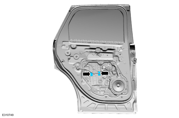
Parking Brake Actuator Motor
The parking brake actuator motors are single speed reversible electric motors mounted on the rear brake calipers. The motors can be serviced separately from the calipers.
Parking Brake Switch
The parking brake switch is a 3 position switch with 2 sets of 3 internal micro switches, one set is for APPLY and one set is for RELEASE. The 3 switch positions are APPLY (pulled up), NEUTRAL (at rest or static) and RELEASE (pushed down).
Whenever the parking brake switch is disconnected and then reconnected, a DTC sets in the ABS module and the ABS module disables the parking brake system. To restore parking brake system functionality and to clear the DTC , the parking brake switch must be moved through all 3 positions twice within 5 seconds pausing for approximately one-half second when the switch is in the NEUTRAL position between each apply and release.
 Description and Operation - Parking Brake - Overview
Overview
The
parking brake system uses 2 switch activated, Electronic Control Unit
(ECU) controlled motors to apply and release the rear brake calipers...
 Diagnosis and Testing - Parking Brake
Diagnostic Trouble Code (DTC) Chart
Diagnostics in this manual assume a certain skill level and knowledge of Ford-specific diagnostic practices. REFER to: Diagnostic Methods (100-00 General Information, Description and Operation)...
Other information:
Lincoln Corsair 2020-2024 Service Manual: Removal and Installation - Differential Pressure Feedback Exhaust Gas Recirculation (EGR) Sensor
Materials Name Specification Motorcraft® Silicone Brake Caliper Grease and Dielectric CompoundXG-3-A ESA-M1C200-AESE-M1C171-A Removal NOTE: Removal steps in this procedure may contain installation details. NOTE: Do not pull the engine appearance cover forward or sideways to remove...
Lincoln Corsair 2020-2024 Owners Manual: Vehicle Storage. Body Styling Kits
Vehicle Storage If you plan on storing your vehicle for 30 days or more, read the following maintenance recommendations to make sure your vehicle stays in good operating condition. We engineer and test all motor vehicles and their components for reliable, regular driving...
Categories
- Manuals Home
- 1st Generation Lincoln Corsair Owners Manual
- 1st Generation Lincoln Corsair Service Manual
- Interior Lamps
- Selecting a Drive Mode. DRIVE MODES
- Exterior Mirrors
- New on site
- Most important about car
Selecting a Drive Mode. DRIVE MODES
Selecting a Drive Mode
Note: Drive mode changes may not be available when the ignition is off.