Lincoln Corsair: Rear Drive Halfshafts / Removal and Installation - Intermediate Shaft
Lincoln Corsair 2020-2026 Service Manual / Chassis / Driveline / Rear Drive Halfshafts / Removal and Installation - Intermediate Shaft
Special Tool(s) / General Equipment
 |
100-001
(T50T-100-A)
Slide Hammer |
 |
205-1076 Link Shaft tool E-Drive Rear Axle |
 |
205-153
(T80T-4000-W)
Handle |
 |
303-D1665
(303-DS005)
Puller, Blind Hole |
Removal
-
Remove the rear halfshaft LH .
Refer to: Rear Halfshaft (205-05 Rear Drive Halfshafts, Removal and Installation).
-
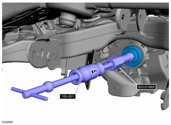
Using the special tools, remove the intermediate shaft.
Use Special Service Tool: 303-D1665 (303-DS005) Puller, Blind Hole. , 100-001 (T50T-100-A) Slide Hammer.
 |
-
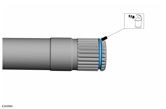
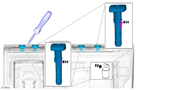
Remove and discard the intermediate shaft retaining circlip.
 |
-
Remove and discard the intermediate shaft dust cover.
 |
-
Remove and discard the intermediate shaft seal.
 |
-
Remove the intermediate shaft bearing.
 |
Installation
-
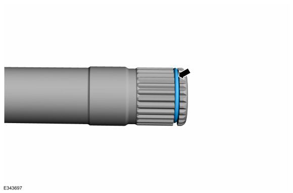
Install the new intermediate shaft retaining circlip.
 |
-
Install the intermediate shaft bearing.
 |
-
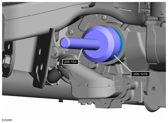
Install the intermediate shaft.
 |
-
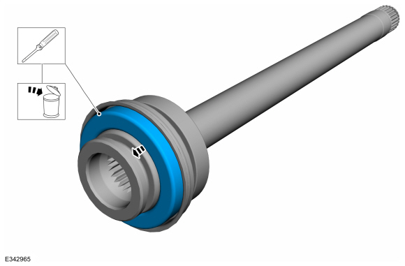
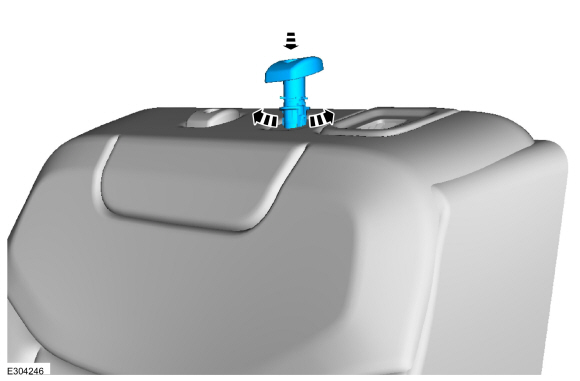
Install the intermediate shaft seal.
Use Special Service Tool: 205-1076 Link Shaft tool E-Drive Rear Axle. , 205-153 (T80T-4000-W) Handle.
 |
-
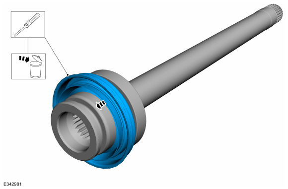
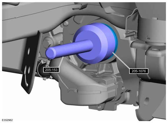
Install the intermediate shaft dust cover.
Use Special Service Tool: 205-1076 Link Shaft tool E-Drive Rear Axle. , 205-153 (T80T-4000-W) Handle.
 |
-
Install the rear halfshaft LH .
Refer to: Rear Halfshaft (205-05 Rear Drive Halfshafts, Removal and Installation).
-
Check and top off the rear electric drive assembly oil level.
Refer to: Drive Assembly Oil Draining and Filling (302-02 Rear Electric Drive Assembly, General Procedures).
 Diagnosis and Testing - Rear Drive Halfshafts
Preliminary Inspection
Visually inspect the CV joints, housing, boots, and clamps for obvious signs of mechanical damage.
If an obvious cause for an observed or reported concern is
found, correct the cause (if possible) before proceeding to the next
step
If the cause is not visually evident, verify the symptom and REFER to Symptom Chart: NVH...
 Removal and Installation - Rear Halfshaft
Special Tool(s) /
General Equipment
100-001
(T50T-100-A)
Slide Hammer
205-832Remover, HalfshaftTKIT-2006C-FFMFLMTKIT-2006C-LMTKIT-2006C-ROW
Removal
NOTICE:
Never pick up or hold the halfshaft by only the inner or
outer Constant Velocity (CV) joint...
Other information:
Lincoln Corsair 2020-2026 Service Manual: Removal and Installation - Solenoid
Materials Name Specification Motorcraft® MERCON® ULV Automatic Transmission FluidXT-12-QULV WSS-M2C949-A, MERCON® ULV Removal NOTICE: Failure to match the replacement solenoid service band to the original solenoid can cause damage to the transmission or erratic engagements and shifts...
Lincoln Corsair 2020-2026 Owners Manual: Daytime Running Lamps - Vehicles With: Configurable Daytime Running Lamps. Daytime Running Lamps - Vehicles With: Daytime Running Lamps (DRL)
Daytime Running Lamps - Vehicles With: Configurable Daytime Running Lamps WARNING: The daytime running lamps system does not activate the rear lamps and may not provide adequate lighting during low visibility driving conditions. Make sure you switch the headlamps on, as appropriate, during all low visibility conditions...
Categories
- Manuals Home
- 1st Generation Lincoln Corsair Owners Manual
- 1st Generation Lincoln Corsair Service Manual
- Refueling - Gasoline
- Programming the Garage Door Opener to Your Garage Door Opener Motor
- Memory Function
- New on site
- Most important about car
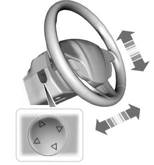
Adjusting the Steering Wheel - Vehicles With: Power Adjustable Steering Column
WARNING: Do not adjust the steering wheel when your vehicle is moving.
Note: Make sure that you are sitting in the correct position.
Copyright © 2026 www.licorsair.com