Lincoln Corsair: Rear Drive Halfshafts / Diagnosis and Testing - Rear Drive Halfshafts
Preliminary Inspection
-
Visually inspect the CV joints, housing, boots, and clamps for obvious signs of mechanical damage.
-
If an obvious cause for an observed or reported concern is
found, correct the cause (if possible) before proceeding to the next
step
-
If the cause is not visually evident, verify the symptom and REFER to Symptom Chart: NVH.
Symptom Chart(s)
Diagnostics in this manual assume a certain skill level and knowledge of Ford-specific diagnostic practices.
REFER to: Diagnostic Methods (100-00 General Information, Description and Operation).
Symptom Chart: NVH
Symptom Chart
| Condition | Actions |
|---|---|
| Driveline clunk - loud clunk when shifting from REVERSE to DRIVE | GO to Pinpoint Test A |
| Driveline clunk — occurs as the vehicle starts to move forward following a stop | GO to Pinpoint Test B |
| Grunting — normally associated with a shudder experienced during acceleration from a complete stop | GO to Pinpoint Test C |
| Driveline vibration - occurs at cruising speeds | GO to Pinpoint Test D |
Pinpoint Tests
 PINPOINT TEST A: DRIVELINE CLUNK- LOUD CLUNK WHEN SHIFTING FROM REVERSE TO DRIVE
|
Normal Operation and Fault Conditions Halfshafts transmit rotary motion through constant velocity joints in a uniform manner. The outer CV joints use balls, have no length compensation and engage in the wheel hubs. The inner CV joints use balls, have length compensation, and are locked in to the differential by a snap-ring. The inner CV joints use balls, have length compensation, and are locked in to the differential by a snap-ring. Possible Sources
|
||||
| A1 CHECK THE HUB NUT TORQUE | ||||
Is the hub nut loose?
|
||||
| A2 CHECK THE TORQUE ON SUSPENSION AND STEERING SYSTEM FASTENERS | ||||
Is the any of the suspension and steering fastener loose?
|
||||
| A3 CHECK THE CONSTANT VELOCITY (CV) BOOTS AND JOINTS FOR WEAR OR DAMAGE | ||||
Was damage found?
|
 PINPOINT TEST B: DRIVELINE CLUNK — OCCURS AS THE VEHICLE STARTS TO MOVE FORWARD FOLLOWING A STOP
 |
Normal Operation and Fault Conditions Halfshafts transmit rotary motion through constant velocity joints in a uniform manner. The outer CV joints use balls, have no length compensation and engage in the wheel hubs. The inner CV joints use balls, have length compensation, and are locked in to the differential by a snap-ring. The inner CV joints use balls, have length compensation, and are locked in to the differential by a snap-ring. Possible Sources
|
||||
| B1 CHECK FOR LOOSE HUB NUT | ||||
Are any hub nuts loose?
|
||||
| B2 CHECK THE TORQUE ON SUSPENSION AND STEERING SYSTEM FASTENERS | ||||
Is the any of the suspension and steering fastener loose?
|
||||
| B3 CHECK THE CONSTANT VELOCITY (CV) BOOTS AND JOINTS FOR WEAR OR DAMAGE | ||||
Was damage found?
|
 PINPOINT TEST C: GRUNTING — NORMALLY ASSOCIATED WITH A SHUDDER EXPERIENCED DURING ACCELERATION FROM A COMPLETE STOP
 |
Normal Operation and Fault Conditions Halfshafts transmit rotary motion through constant velocity joints in a uniform manner. The outer CV joints use balls, have no length compensation and engage in the wheel hubs. The inner CV joints use balls, have length compensation, and are locked in to the differential by a snap-ring. The inner CV joints use balls, have length compensation, and are locked in to the differential by a snap-ring. Possible Sources
|
||||
| C1 CHECK THE OUTER CONSTANT VELOCITY (CV) JOINT FOR CORRECT SEATING INTO THE HUB | ||||
Is the outer Constant Velocity (CV) joint seated correctly into the hub?
|
 PINPOINT TEST D: DRIVELINE VIBRATION - OCCURS AT CRUISING SPEEDS
 |
Normal Operation and Fault Conditions Halfshafts transmit rotary motion through constant velocity joints in a uniform manner. The outer CV joints use balls, have no length compensation and engage in the wheel hubs. The inner CV joints use balls, have length compensation, and are locked in to the differential by a snap-ring. The inner CV joints use balls, have length compensation, and are locked in to the differential by a snap-ring. Possible Sources
|
||||
| D1 CHECK THE OUTER CONSTANT VELOCITY (CV) JOINT FOR CORRECT SEATING INTO THE HUB | ||||
Is the outer Constant Velocity (CV) joint seated correctly into the hub?
|
Differential Seals
NOTICE: When installing shafts, do not allow splines to contact seals during installation or damage to the seals may occur.
Halfshaft seals are susceptible to the same types of damage as drive pinion seals if incorrectly installed. The seal bore must be clean and the lip handled carefully to avoid cutting or tearing it. The seal journal surface must be free of nicks, gouges and rough surface texture.
For information on differential seals,
REFER to: Rear Halfshaft Seal (205-02 Rear Drive Axle/Differential, Removal and Installation).
REFER to: Rear Halfshaft Seal (205-02 Rear Drive Axle/Differential, Removal and Installation).
 Removal and Installation - Intermediate Shaft
Special Tool(s) /
General Equipment
100-001
(T50T-100-A)
Slide Hammer
205-1076Link Shaft tool E-Drive Rear Axle
205-153
(T80T-4000-W)
Handle
303-D1665
(303-DS005)
Puller, Blind Hole
Removal
Remove the rear halfshaft LH ...
Other information:
Lincoln Corsair 2020-2026 Service Manual: Description and Operation - Transmission Cooling - Overview
Transmission Cooling This vehicle is equipped with an external transmission fluid cooler. The transmission fluid cooler is an oil-to-coolant fluid cooler which is mounted to the lower LH side of the transmission. The cooling system also consists of a coolant control valve mounted to the upper rear of the transmission...
Lincoln Corsair 2020-2026 Service Manual: General Procedures - Lead Terminal Repair
Materials Name Specification Motorcraft® Ultra-Clear Spray Glass CleanerZC-23 ESR-M14P5-A Repair Bring the vehicle up to at least the specified room temperature or above. NOTE: The new terminal covers the original terminal location, but it must be placed so the terminal conductive areas will be placed on a good conductive base...
Categories
- Manuals Home
- 1st Generation Lincoln Corsair Owners Manual
- 1st Generation Lincoln Corsair Service Manual
- Auto Hold (IF EQUIPPED)
- Automatic Transmission - 8-Speed Automatic Transmission – 8F35/8F40
- Capacities and Specifications - 2.0L
- New on site
- Most important about car
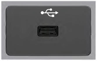
USB Port
WARNING: Driving while distracted can result in loss of vehicle control, crash and injury. We strongly recommend that you use extreme caution when using any device that may take your focus off the road. Your primary responsibility is the safe operation of your vehicle. We recommend against the use of any hand-held device while driving and encourage the use of voice-operated systems when possible. Make sure you are aware of all applicable local laws that may affect the use of electronic devices while driving.
USB A


 PINPOINT TEST A: DRIVELINE CLUNK- LOUD CLUNK WHEN SHIFTING FROM REVERSE TO DRIVE