Lincoln Corsair: Fuel Charging and Controls - 2.0L EcoBoost (177kW/240PS) – MI4 / Removal and Installation - High-Pressure Fuel Pump
Removal
NOTICE:
Do not loosen any fittings or plugs on the high-pressure fuel pump.
-
With the vehicle in NEUTRAL, position it on a hoist.
Refer to: Jacking and Lifting - Overview (100-02 Jacking and Lifting, Description and Operation).
-
Release the fuel system pressure.
Refer to: Fuel System Pressure Release (310-00A Fuel System - General
Information - 2.0L EcoBoost (177kW/240PS) – MI4, General Procedures).
-
Disconnect the battery.
Refer to: Battery Disconnect and Connect (414-01 Battery, Mounting and Cables, General Procedures).
-
Remove the air cleaner outlet pipe.
Refer to: Air Cleaner Outlet Pipe (303-12A Intake Air Distribution and
Filtering - 2.0L EcoBoost (177kW/240PS) – MI4, Removal and
Installation).
-
Remove the exhaust gas recirculation valve.
Refer to: Exhaust Gas Recirculation (EGR) Valve (303-08A Engine
Emission Control - 2.0L EcoBoost (177kW/240PS) – MI4, Removal and
Installation).
Refer to: Exhaust Gas Recirculation (EGR) Valve (303-08B Engine
Emission Control - 2.3L EcoBoost (199kW/270PS), Removal and
Installation).
-
Disconnect the high-pressure fuel pump electrical connector.
-
NOTE:
When removing or installing the high-pressure fuel
pump insulator, spreading the openings will reduce the risk of damage.
Remove the high-pressure fuel pump insulator.
-
Disconnect the electrical connector, then detach the wiring harness retainers and move out of the way.
-
Disconnect the high-pressure fuel pump fuel feed tube spring lock coupling.
Refer to: Spring Lock Couplings (310-00A Fuel System - General
Information - 2.0L EcoBoost (177kW/240PS) – MI4, General Procedures).
-
NOTICE:
To release the fuel pressure in the high-pressure
fuel tube, wrap the high-pressure fuel pump flare nut with a shop towel
to absorb any residual fuel pressure during the loosening of
high-pressure fuel pump flare nut.
Remove the high-pressure fuel tube bracket bolts. Loosen
the high-pressure fuel tube flare nuts, then disconnect, remove and
discard the high-pressure fuel tube.
-
-
Alternately loosen the high-pressure fuel pump bolts
one complete revolution at a time. Remove and discard the high-pressure
fuel pump bolts.
-
Remove the high-pressure fuel pump.
-
Remove and discard the high-pressure fuel pump O-ring seal.
-
Remove the high-pressure fuel pump tappet.
Installation
-
Inspect the high-pressure fuel pump roller tappet. If
any flat spots or scoring are found, especially in the indicated areas,
then inspect the high-pressure fuel pump and the high-pressure fuel pump
roller tappet drive lobe. Install new components as needed.
-
Remove the right front wheel and tire.
Refer to: Wheel and Tire (204-04A Wheels and Tires, Removal and Installation).
-
Remove the retainers, then position the fender splash shield aside.
-
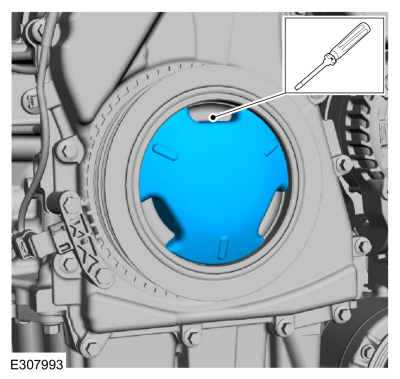
If equipped, release the tabs and remove the crankshaft pulley cover.
-
If equipped, inspect the 3 crankshaft pulley cover tabs
for damage, if damaged replace the crankshaft pulley cover.
-
NOTICE:
Only rotate the crankshaft Clockwise (CW) or damage to the engine may occur.
NOTE:
The cam lobe for the high-pressure fuel pump must be at BDC for the high-pressure fuel pump installation.
With the help of an assistant, using the crankshaft
pulley bolt, turn the crankshaft until the high-pressure fuel pump cam
lobe is at BDC .
-
If equipped.
-
Align and insert 2 tabs of the crankshaft pulley
cover into the open spaces between the ribs of the crankcase pulley.
-
Press the third tab firmly into position until a snap is heard or felt.
-
Verify that the crankshaft pulley cover is securely in place.
-
Position back the fender splash shield, then install the retainers.
-
Install the right front wheel and tire.
Refer to: Wheel and Tire (204-04A Wheels and Tires, Removal and Installation).
-
Apply clean engine oil to the high-pressure fuel pump drive unit bore, the drive lobe and the roller tappet.
Refer to: Specifications (303-01A Engine - 2.0L EcoBoost (177kW/240PS) – MI4, Specifications).
-
NOTICE:
The roller tappets roller goes down towards the camshaft.
NOTE:
Align the notch on the high-pressure fuel pump
tappet and with the groove in the high-pressure fuel pump drive unit
bore.
Install the high-pressure fuel pump tappet.
-
Install a new high-pressure fuel pump O-ring seal. Apply
clean engine oil to the new high-pressure fuel pump O-ring seal.
Refer to: Specifications (303-01A Engine - 2.0L EcoBoost (177kW/240PS) – MI4, Specifications).
-
NOTE:
Install new high-pressure fuel pump bolts.
Install the high-pressure fuel pump and the new
high-pressure fuel pump bolts. Alternately tighten each bolt one half
revolution until seated, then tighten in the following 2 stages.
Torque:
Stage 1:
Tighten to: :
115 lb.in (13 Nm)
Stage 2:
Tighten an additional: :
45°
-
NOTE:
Make sure that a new high-pressure fuel tube is installed.
-
Install the new high-pressure fuel tube and the
bracket bolts, then tighten the high pressure fuel tube flare nuts and
the bracket bolts only finger tight at this stage.
-
Calculate the correct torque wrench setting for the
following torque using the Torque Wrench Adapter Formulas.
Torque:
High pressure fuel tube flare nuts, :
Stage 1:
Tighten to: :
62 lb.in (7 Nm)
Stage 2:
Tighten to: :
89 lb.in (10 Nm)
Stage 3:
Tighten an additional: :
38°
High-pressure fuel tube bracket bolts, tighten to: :
97 lb.in (11 Nm)
-
Connect the high-pressure fuel pump fuel feed tube spring lock coupling.
Refer to: Spring Lock Couplings (310-00A Fuel System - General
Information - 2.0L EcoBoost (177kW/240PS) – MI4, General Procedures).
-
Connect the electrical connector, then attach the wiring harness retainers.
-
NOTE:
When removing or installing the high-pressure fuel
pump insulator, spreading the openings will reduce the risk of damage.
Install the high-pressure fuel pump insulator.
-
Connect the high-pressure fuel pump electrical connector.
-
Install the exhaust gas recirculation valve.
Refer to: Exhaust Gas Recirculation (EGR) Valve (303-08A Engine
Emission Control - 2.0L EcoBoost (177kW/240PS) – MI4, Removal and
Installation).
Refer to: Exhaust Gas Recirculation (EGR) Valve (303-08B Engine
Emission Control - 2.3L EcoBoost (199kW/270PS), Removal and
Installation).
-
Install the air cleaner outlet pipe.
Refer to: Air Cleaner Outlet Pipe (303-12A Intake Air Distribution and
Filtering - 2.0L EcoBoost (177kW/240PS) – MI4, Removal and
Installation).
-
Connect the battery.
Refer to: Battery Disconnect and Connect (414-01 Battery, Mounting and Cables, General Procedures).
-
Pressurize the fuel system.
Refer to: Fuel System Pressure Release (310-00A Fuel System - General
Information - 2.0L EcoBoost (177kW/240PS) – MI4, General Procedures).
Special Tool(s) /
General Equipment
303-1567Sizer, Teflon SealTKIT-2010C-FLM
307-005
(T59L-100-B)
Slide Hammer
310-205Fuel Injector Brush
310-206Remover, Fuel InjectorTKIT-2009A-FLM
310-207Installer, Fuel Injector Seal AssemblyTKIT-2009A-FLM
Removal
Release the fuel system pressure...
Removal
Remove the valve cover.
Refer to: Valve Cover (303-01A Engine - 2.0L EcoBoost (177kW/240PS) – MI4, Removal and Installation).
Remove the high-pressure fuel pump drive unit bolts, then remove the high-pressure fuel pump drive unit...
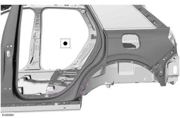
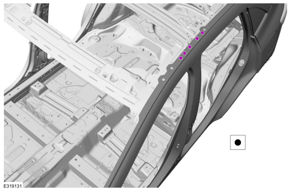
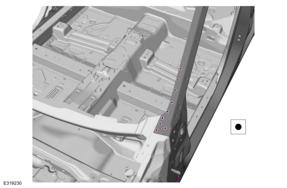
Other information:
Special Tool(s) /
General Equipment
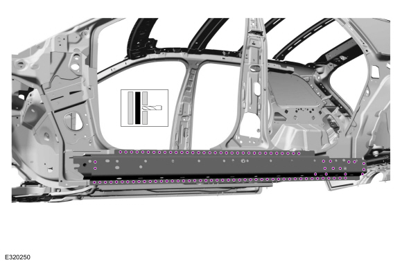
Resistance Spotwelding Equipment
Spherical Cutter
Hot Air Gun
Air Body Saw
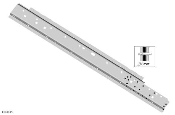
8 mm Drill Bit
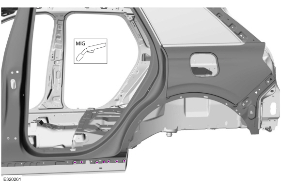
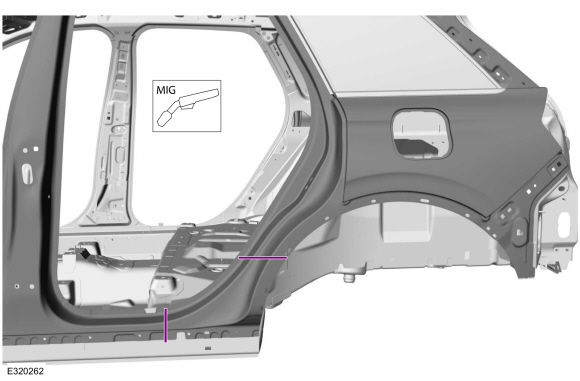
MIG/MAG Welding Equipment
Spot Weld Drill Bit
Locking Pliers
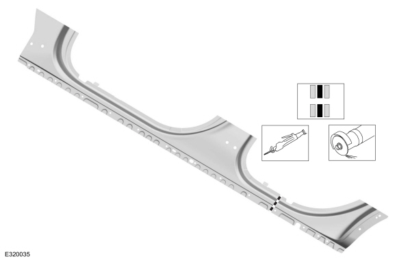
Materials
Name
Specification
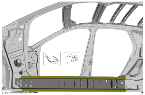
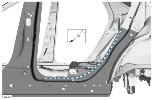
Seam SealerTA-2-B, 3M™ 08308, LORD Fusor® 803DTM
-
Flexible Foam Repair3M™ 08463, LORD Fusor® 121
-
..
Special Tool(s) /
General Equipment
Vehicle/Axle Stands
Removal
Remove the rear wheel bearing and wheel hub.
Refer to: Wheel Bearing and Wheel Hub - FWD (204-02 Rear Suspension, Removal and Installation).
Remove the rear toe link.
Refer to: Toe Link (204-02 Rear Suspension, Removal and Installation).
Raise the suspension to the curb height.
Use ..
 Removal and Installation - Fuel Rail
 Removal and Installation - High-Pressure Fuel Pump Drive Unit