Lincoln Corsair: Fuel Charging and Controls - 2.0L EcoBoost (177kW/240PS) – MI4 / Removal and Installation - Fuel Rail
Special Tool(s) / General Equipment
 |
303-1567 Sizer, Teflon Seal TKIT-2010C-FLM |
 |
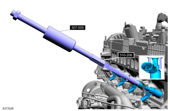
307-005
(T59L-100-B)
Slide Hammer |
 |
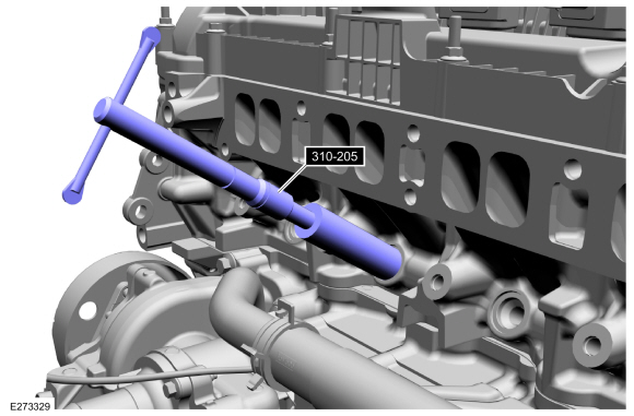
310-205 Fuel Injector Brush |
 |
310-206 Remover, Fuel Injector TKIT-2009A-FLM |
 |
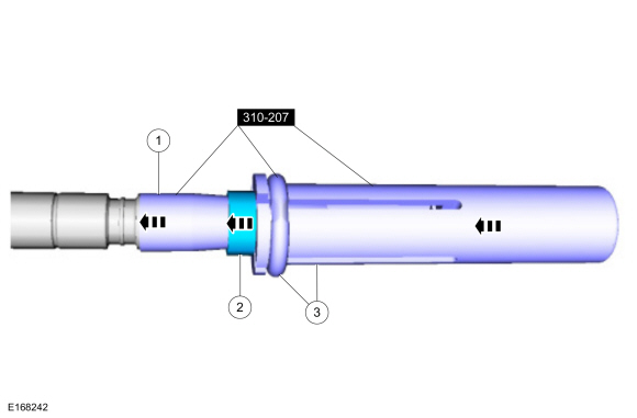
310-207 Installer, Fuel Injector Seal Assembly TKIT-2009A-FLM |
Removal
-
Release the fuel system pressure.
Refer to: Fuel System Pressure Release (310-00A Fuel System - General Information - 2.0L EcoBoost (177kW/240PS) – MI4, General Procedures).
-
Disconnect the battery.
Refer to: Battery Disconnect and Connect (414-01 Battery, Mounting and Cables, General Procedures).
-
Remove the intake manifold.
Refer to: Intake Manifold (303-01A Engine - 2.0L EcoBoost (177kW/240PS) – MI4, Removal and Installation).
-
Remove the air cleaner outlet pipe.
Refer to: Air Cleaner Outlet Pipe (303-12A Intake Air Distribution and Filtering - 2.0L EcoBoost (177kW/240PS) – MI4, Removal and Installation).
-
Disconnect the high-pressure fuel pump electrical connector.
 |
-
NOTE: When removing or installing the high-pressure fuel pump insulator, spreading the openings will reduce the risk of damage.
Remove the high-pressure fuel pump insulator.
 |
-
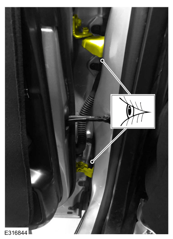
Disconnect the electrical connector, then detach the wiring harness retainers and move out of the way.
 |
-
NOTICE: To release the fuel pressure in the high-pressure fuel tube, wrap the high-pressure fuel pump flare nut with a shop towel to absorb any residual fuel pressure during the loosening of high-pressure fuel pump flare nut.
Remove the high-pressure fuel tube bracket bolts. Loosen the high-pressure fuel tube flare nuts, then disconnect, remove and discard the high-pressure fuel tube.
 |
-
-
Detach the wire harness retainers from the fuel rail.
-
Remove the fuel rail insulator.
-
Detach the wire harness retainers from the fuel rail.
 |
-
-
Disconnect the wire harness retainer from the fuel rail.
-
Disconnect the fuel rail sensor electrical connector.
-
Disconnect the fuel injector electrical connectors.
-
Remove the fuel rail wire harness.
-
Disconnect the wire harness retainer from the fuel rail.
 |
-
NOTICE: Pull out the fuel rails in the direction of the fuel injector axis or damage may occur to the fuel injectors.
NOTE: When removing the fuel rails, the fuel injectors may remain in the cylinder head and require the use of a Fuel Injector Remover tool to extract. Wiggling the fuel injector and twisting the fuel injector by hand to break it loose may allow the fuel injector to be removed.
-
Use compressed air to remove any dirt or foreign
material from the cylinder head, the engine block and the general
surrounding area of the fuel rail and the fuel injectors.
-
Remove and discard the bolts, then remove the fuel rail.
-
Use compressed air to remove any dirt or foreign
material from the cylinder head, the engine block and the general
surrounding area of the fuel rail and the fuel injectors.
 |
-
Remove the fuel injectors from the fuel rail.
 |
-
Remove and discard the fuel injector clips.
 |
-
NOTICE: Use minimal force to remove the fuel injectors with the Fuel Injector Remover tool or damage to the fuel injector assembly may occur. Wiggling the fuel injector and twisting by hand to break it loose may allow the fuel injector to be removed.
NOTE: Commercially available OTC 5028 8-1/2" long slide hammer may be substituted for 307-005 where there are clearance concerns.
Using the special tools, remove any of the fuel injectors that remained in the cylinder head.
Use Special Service Tool: 307-005 (T59L-100-B) Slide Hammer. , 310-206 Remover, Fuel Injector.
 |
-
NOTICE: Do not use compressed air to clean the tip of the fuel injector.
NOTICE: Do not use a brush to clean the tip of the fuel injector.
-
Thoroughly clean any residual fuel or foreign
material from the cylinder head, the engine block, the general
surrounding area of the fuel rails and the fuel injectors.
-
Using the special tool, clean the cylinder head fuel injector bores.
Use Special Service Tool: 310-205 Fuel Injector Brush.
-
Thoroughly clean any residual fuel or foreign
material from the cylinder head, the engine block, the general
surrounding area of the fuel rails and the fuel injectors.
 |
-
NOTE: Note the correct orientation of the fuel injector support rings for correct installation.
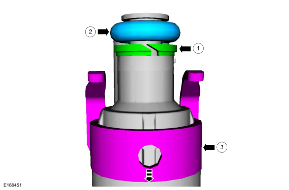
Remove and discard the fuel injector O-rings. Remove and discard the fuel injector support rings.
 |
-
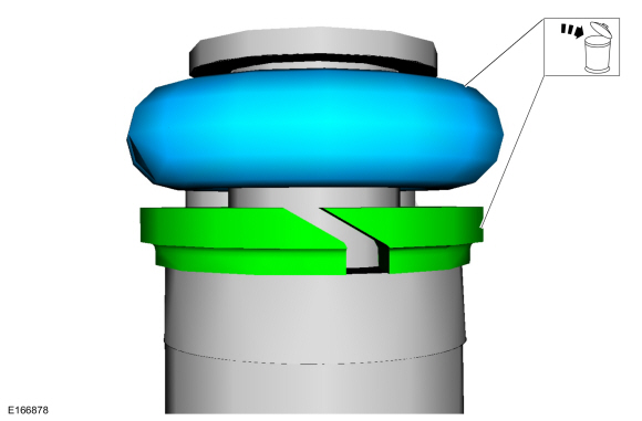
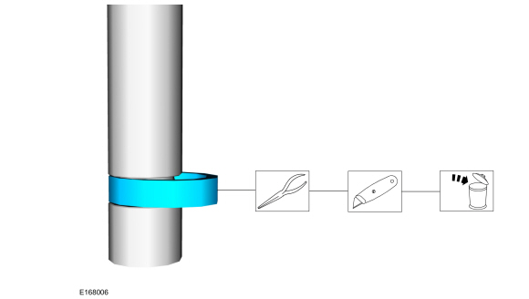
NOTICE: Use care when removing the lower Teflon® seals, not to scratch, nick or gouge the fuel injectors.
NOTICE: Do not attempt to cut the lower Teflon® seal without first pulling it away from the fuel injector or damage to the fuel injector may occur.
-
Pull the lower Teflon® seal away from the fuel injector.
-
Carefully cut and discard the lower fuel injector Teflon® seal.
-
Pull the lower Teflon® seal away from the fuel injector.
 |
Installation
-
NOTICE: Do not lubricate the new lower Teflon® fuel injector seals.
-
Install the Teflon® Seal Guide onto the fuel injector tip.
Use Special Service Tool: 310-207 Installer, Fuel Injector Seal Assembly.
-
NOTICE: Once the Teflon® seal is installed on the Teflon® Seal Guide, it should immediately be installed onto the fuel injector to avoid excessive expansion of the Teflon® seal.
NOTE: Make sure that new lower fuel injector Teflon® seals are installed.
Install the new Teflon® seals onto the Teflon® Seal Guide, using the Pusher Tool, slide the Teflon® seals along the Teflon® Seal Guide.
-
Using the Pusher Tool, slide the Teflon® seals off
of the Teflon® Seal Guide and into the groove on the fuel injectors.
Use Special Service Tool: 310-207 Installer, Fuel Injector Seal Assembly.
-
Remove the special tools.
-
Install the Teflon® Seal Guide onto the fuel injector tip.
 |
-
NOTE: Make sure the Teflon® seal is fully seated in the groove on the fuel injector before sizing the Teflon® seal.
-
Massage and warm the Teflon® seal with your fingers
before the Teflon® seal sizer tool is installed. This will aid in
installing the Teflon® seal sizer tool.
-
NOTE: The beveled opening of the Teflon® seal sizer tool goes away from the seal.
Position the Teflon® seal sizer tool with the larger opening towards the Teflon® seal. Push while turning the Teflon® seal sizer tool 180 degrees.
Use Special Service Tool: 303-1567 Sizer, Teflon Seal.
-
Once the Teflon® seal sizer tool is installed, check
and make sure the Teflon® seal is in the sizing portion of the Teflon®
seal sizer tool.
-
After one minute, turn the Teflon® seal sizer tool back 180 degrees and remove.
-
Massage and warm the Teflon® seal with your fingers
before the Teflon® seal sizer tool is installed. This will aid in
installing the Teflon® seal sizer tool.
 |
-
NOTE: Make sure that new fuel injector support rings and new fuel injector O-ring seals are installed.
-
NOTICE: The new the fuel injector support rings must be installed in the correct orientation with the wide surface area facing up against the fuel injector O-ring seals. Improperly installed support rings may cause the fuel system to leak.
Install the new the fuel injector support rings.
-
NOTE: Do not lubricate the new lower Teflon® fuel injector seals.
Install the new fuel injector O-rings.
-
Install the new the fuel injector clips.
-
 |
-
NOTE: The anti-rotation finger of the fuel injector clip must slip into the groove of the fuel rail cup.
Install the fuel injectors to the fuel rail.
|
-
NOTE: Do not lubricate the new lower Teflon® fuel injector seals.
-
NOTE: No sudden impact force is allowed.
NOTE: Make sure that new fuel rail bolts are installed.
Press the fuel rail down into the cylinder head injector bores by hand, then install and hand start the new number 3 and 4 bolts.
-
Release the force before tightening.
-
Install the remaining new bolts. Tighten all of the
fuel rail bolts in the sequence shown and in the following 5 stages.
Torque:
Stage 1: Tighten to: : 89 lb.in (10 Nm)
Stage 2: Back off to: : 0 lb.in (0 Nm)
Stage 3: Wait 5 s
Stage 4: Tighten to: : 124 lb.in (14 Nm)
Stage 5: Tighten an additional: : 30°
-
 |
-
-
Install the fuel rail wire harness, connect the wire harness retainer to the fuel rail.
-
Connect the fuel injector electrical connectors.
-
Connect the fuel rail sensor electrical connector.
-
Install the fuel rail wire harness, connect the wire harness retainer to the fuel rail.
|
-
-
Install the fuel rail insulator.
-
Attach the wire harness retainers to the fuel rail.
-
Install the fuel rail insulator.
|
-
NOTE: Make sure that a new high-pressure fuel tube is installed.
-
Install the new high-pressure fuel tube and the
bracket bolts, then tighten the high pressure fuel tube flare nuts and
the bracket bolts only finger tight at this stage.
-
Calculate the correct torque wrench setting for the
following torque using the Torque Wrench Adapter Formulas.
Torque:
High pressure fuel tube flare nuts, :
Stage 1: Tighten to: : 62 lb.in (7 Nm)
Stage 2: Tighten to: : 89 lb.in (10 Nm)
Stage 3: Tighten an additional: : 38°
High-pressure fuel tube bracket bolts, tighten to: : 97 lb.in (11 Nm)
-
Install the new high-pressure fuel tube and the
bracket bolts, then tighten the high pressure fuel tube flare nuts and
the bracket bolts only finger tight at this stage.
 |
-
Attach the wiring harness retainers, then connect the electrical connector.
|
-
NOTE: When removing or installing the high-pressure fuel pump insulator, spreading the openings will reduce the risk of damage.
Install the high-pressure fuel pump insulator.
|
-
Connect the high-pressure fuel pump electrical connector.
|
-
Install the air cleaner outlet pipe.
Refer to: Air Cleaner Outlet Pipe (303-12A Intake Air Distribution and Filtering - 2.0L EcoBoost (177kW/240PS) – MI4, Removal and Installation).
-
Install the intake manifold.
Refer to: Intake Manifold (303-01A Engine - 2.0L EcoBoost (177kW/240PS) – MI4, Removal and Installation).
-
Connect the battery.
Refer to: Battery Disconnect and Connect (414-01 Battery, Mounting and Cables, General Procedures).
-
Pressurize the fuel system.
Refer to: Fuel System Pressure Release (310-00A Fuel System - General Information - 2.0L EcoBoost (177kW/240PS) – MI4, General Procedures).
 Removal and Installation - Fuel Pump Driver Module (FPDM)
Removal
NOTE:
The fuel pump driver module is attached to the top of the fuel tank.
For component location information.
Refer to: Fuel Charging and Controls - Component Location (303-04A Fuel
Charging and Controls - 2...
 Removal and Installation - High-Pressure Fuel Pump
Removal
NOTICE:
Do not loosen any fittings or plugs on the high-pressure fuel pump.
With the vehicle in NEUTRAL, position it on a hoist.
Refer to: Jacking and Lifting - Overview (100-02 Jacking and Lifting, Description and Operation)...
Other information:
Lincoln Corsair 2020-2026 Service Manual: Removal and Installation - Front Door Window Regulator Motor
Removal NOTE: Left hand (LH) shown, right hand (RH) similar. NOTE: For front door window regulator motors that are non-functional it may be necessary to remove the front door window regulator motor prior to securing the front door window glass...
Lincoln Corsair 2020-2026 Service Manual: Removal and Installation - Front Door Moulding
Special Tool(s) / General Equipment Interior Trim Remover Removal NOTE: Removal steps in this procedure may contain installation details. NOTE: LH door shown, RH door similar. NOTE: Do not use excessive force when removing retainers, to avoid damage to moulding...
Categories
- Manuals Home
- 1st Generation Lincoln Corsair Owners Manual
- 1st Generation Lincoln Corsair Service Manual
- Normal Scheduled Maintenance
- Exterior Mirrors
- Child Safety Locks
- New on site
- Most important about car
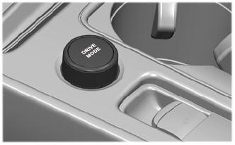
Selecting a Drive Mode. DRIVE MODES
Selecting a Drive Mode
Note: Drive mode changes may not be available when the ignition is off.