
Lincoln Corsair: Engine Emission Control - 2.0L EcoBoost (177kW/240PS) – MI4 / Removal and Installation - Exhaust Gas Recirculation (EGR) Coolant Outlet Temperature Sensor
Materials
| Name | Specification |
|---|---|
| Motorcraft® Silicone Brake Caliper Grease and Dielectric Compound XG-3-A |
ESA-M1C200-A ESE-M1C171-A |
Removal
NOTE: Removal steps in this procedure may contain installation details.
-
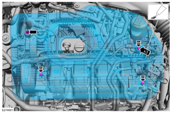
NOTE: Do not pull the engine appearance cover forward or sideways to remove. Failure to press straight upward on the underside of the cover at the attachment points may result in damage to the cover or engine components.
-
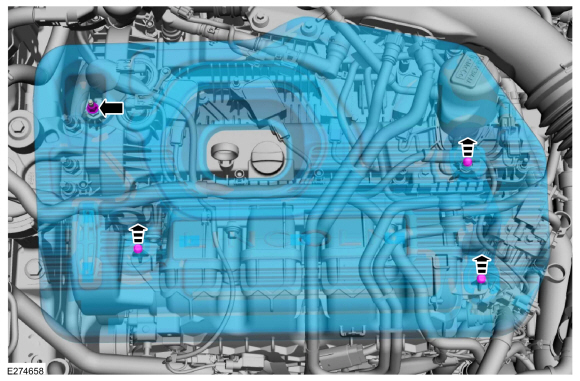
Remove the engine appearance cover nut.
-
Place your hand under the engine appearance cover at
each grommet location and push straight up to release each grommet from
the studs.
-
After all of the grommets have been released from the studs, remove the appearance cover from the engine.
-
Remove the engine appearance cover nut.
 |
-
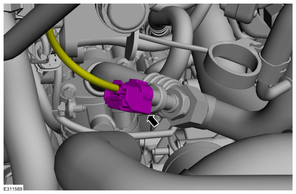
Disconnect the electrical connector.
 |
-
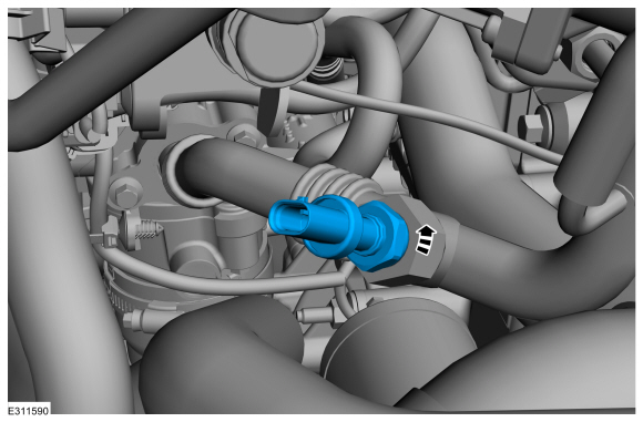
NOTE: When removing the sensor, use a suitable spanner on both the sensor body and the sensor mounting boss, to prevent the removal force from damaging the EGR tube.
Remove the EGR coolant outlet temperature sensor.
 |
-
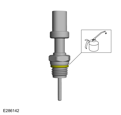
Lubricate the o-ring seal with clean engine oil. Replace the o-ring if necessary.
 |
Installation
-
To install, reverse the removal procedure.
-
-
NOTE: Lubricating the grommets with silicone grease aids in the installation of the engine appearance cover, and any future removal and installation of the cover.
Lubricate each grommet with silicone grease.
Material: Motorcraft® Silicone Brake Caliper Grease and Dielectric Compound / XG-3-A (ESA-M1C200-A) (ESE-M1C171-A)
-
If the engine appearance cover stud bolt is loosened
or removed, it must be installed/tightened into the valve cover.
Torque: 62 lb.in (7 Nm)
-
Position the engine appearance cover onto the engine with the grommets aligned with the studs.
-
Press down on the engine appearance cover at each grommet location to attach the grommets onto the studs.
-
Install the engine appearance cover nut.
Torque: 44 lb.in (5 Nm)
-
 |
 Removal and Installation - Exhaust Gas Recirculation (EGR) Back Pressure Sensor
Materials
Name
Specification
Motorcraft® Silicone Brake Caliper Grease and Dielectric CompoundXG-3-A
ESA-M1C200-AESE-M1C171-A
Removal
NOTE:
Removal steps in this procedure may contain installation details...
 Removal and Installation - Exhaust Gas Recirculation (EGR) Cooler
Removal
NOTE:
Removal steps in this procedure may contain installation details.
Remove the air cleaner.
Refer to: Air Cleaner (303-12A Intake Air Distribution and Filtering -
2...
Other information:
Lincoln Corsair 2020-2024 Service Manual: Diagnosis and Testing - Steering Wheel and Column Electrical Components
Diagnostic Trouble Code (DTC) Chart Diagnostics in this manual assume a certain skill level and knowledge of Ford-specific diagnostic practices. REFER to: Diagnostic Methods (100-00 General Information, Description and Operation). Diagnostic Trouble Code Chart Module DTC Description Action BCM B108A..
Lincoln Corsair 2020-2024 Service Manual: Removal and Installation - Brake Disc
Materials Name Specification Motorcraft® Metal Brake Parts CleanerPM-4-A, PM-4-B, APM-4-C - Removal WARNING: Service actions on vehicles equipped with electronic brake booster and electronic parking brakes may cause unexpected brake application, which could result in injury to hands or fingers. Put the brake system into service mode prior to servicing or re..
Categories
- Manuals Home
- 1st Generation Lincoln Corsair Owners Manual
- 1st Generation Lincoln Corsair Service Manual
- Interior Lamps
- Memory Function
- Programming the Garage Door Opener to Your Garage Door Opener Motor
- New on site
- Most important about car
360 Degree Camera Cameras
Locating the Rear View Camera
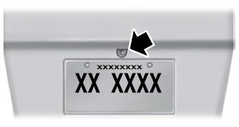
The rear view camera is on the tailgate.
Locating the Front View Camera
