Lincoln Corsair: Engine - 2.0L EcoBoost (177kW/240PS) – MI4 / Removal and Installation - Cylinder Head
Special Tool(s) /
General Equipment
| Oil Drain Equipment |
| Hose Clamp Remover/Installer |
Materials
| Name |
Specification |
Motorcraft® High Performance Engine RTV Silicone
TA-357 |
WSE-M4G323-A6
|
Removal
NOTICE:
Do not loosen or remove the crankshaft pulley bolt without
first installing the special tools as instructed in this procedure. The
crankshaft pulley and the crankshaft timing sprocket are not keyed to
the crankshaft. The crankshaft, the crankshaft sprocket and the pulley
are fitted together by friction. For that reason, the crankshaft
sprocket is also unfastened if the pulley bolt is loosened. Before any
repair requiring loosening or removal of the crankshaft pulley bolt, the
crankshaft and camshafts must be locked in place by the special service
tools, otherwise severe engine damage can occur.
NOTICE:
During engine repair procedures, cleanliness is extremely
important. All parts must be thoroughly cleaned and any foreign
material, including any material created while cleaning gasket surfaces,
that enters the oil passages, coolant passages or the oil pan, can
cause engine failure.
NOTICE:
The turbocharger compressor vanes can be damaged by even the
smallest particles. When removing any turbocharger or engine air intake
system component, ensure that no debris enters the system. Failure to
do so may result in damage to the turbocharger.
-
With the vehicle in NEUTRAL, position it on a hoist.
Refer to: Jacking and Lifting - Overview (100-02 Jacking and Lifting, Description and Operation).
-
Release the fuel system pressure.
Refer to: Fuel System Pressure Release (310-00A Fuel System - General
Information - 2.0L EcoBoost (177kW/240PS) – MI4, General Procedures).
-
Remove the battery tray.
Refer to: Battery Tray - 2.0L EcoBoost (177kW/240PS) – MI4/2.3L
EcoBoost (199kW/270PS) (414-01 Battery, Mounting and Cables, Removal and
Installation).
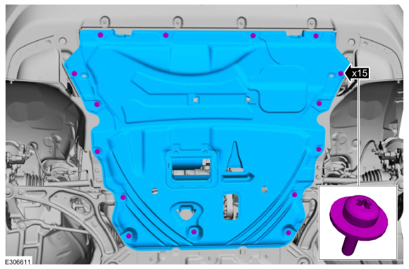
-
Remove the retainers and the underbody shield.
-
Drain the cooling system.
Refer to: Engine Cooling System Draining, Vacuum Filling and Bleeding
(303-03B Engine Cooling - 2.3L EcoBoost (199kW/270PS), General
Procedures).
-
Remove the intake manifold.
Refer to: Intake Manifold (303-01A Engine - 2.0L EcoBoost (177kW/240PS) – MI4, Removal and Installation).
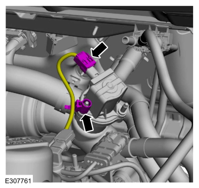
-
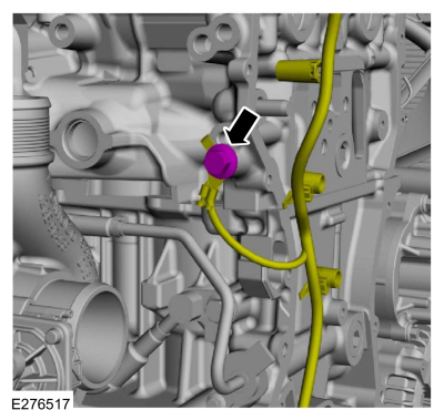
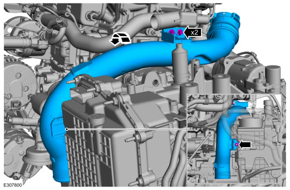
Disconnect the CAC tube bypass valve electrical connector and wire retainer.
-
Disconnect the HO2S electrical connector and the wiring harness retainer.
-
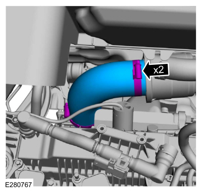
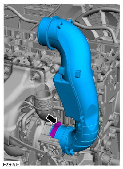
Loosen the clamps and remove the CAC tube.
-
Release the clip and remove the CAC pipe.
-
Loosen the clamp and position the LH front CAC tube aside.
-
-
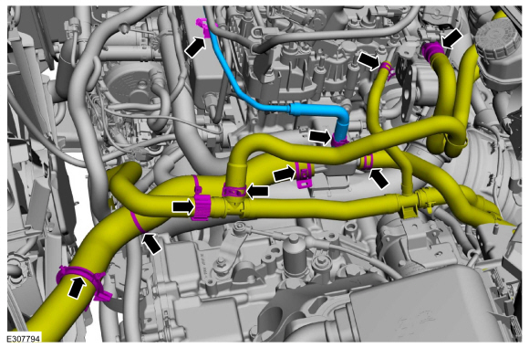
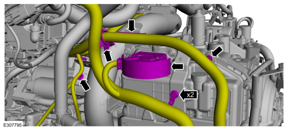
Detach the coolant hose retainers.
-
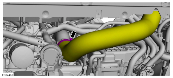
Disconnect heater hose from the EGR cooler.
-
Release the clamp, retainer and remove the degas bottle coolant hose.
Use the General Equipment: Hose Clamp Remover/Installer
-
Release the clamps and disconnect the coolant hoses and position aside.
Use the General Equipment: Hose Clamp Remover/Installer
-
-
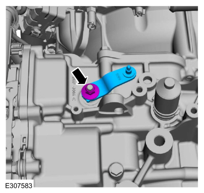
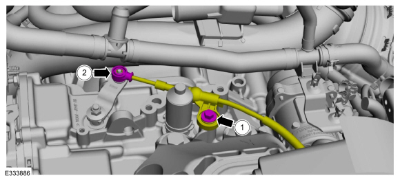
Disconnect the manual park release cable from the manual control lever.
-
Remove the bolt and position the manual park release cable aside.
-
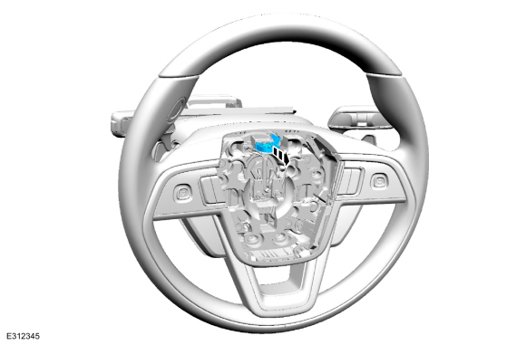
Remove the nut and the manual control lever.
-
Disconnect the transmission wiring harness connector and detach the retainers.
-
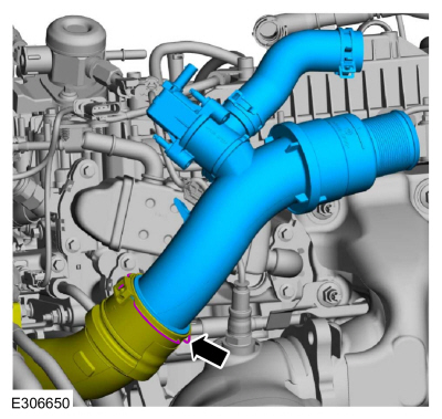
Remove the nut, bolts and the CAC intake pipe.
-
Remove the camshafts.
Refer to: Camshafts (303-01A Engine - 2.0L EcoBoost (177kW/240PS) – MI4, Removal and Installation).
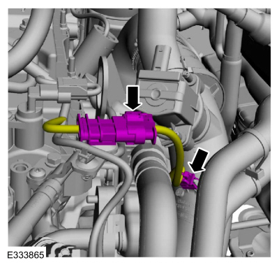
-
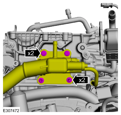
Disconnect the exhaust manifold back pressure sensor, and the ECT sensor wiring harness electrical connectors.
-
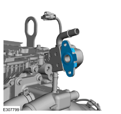
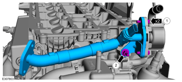
Remove the stud bolt, bolts and the EGR inlet tube assembly.
-
Remove and discard the EGR inlet tube gasket.
-
Loosen the clamp and remove the CAC pipe.
-
Remove the bolt and ground wire.
-
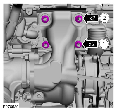
Remove the turbocharger nuts.
-
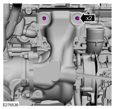
Remove and discard the upper cylinder head studs.
-
-
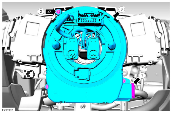
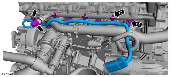
Disconnect the fuel rail wiring harness electrical connectors.
-
Detach the wiring harness retainers and remove harness.
-
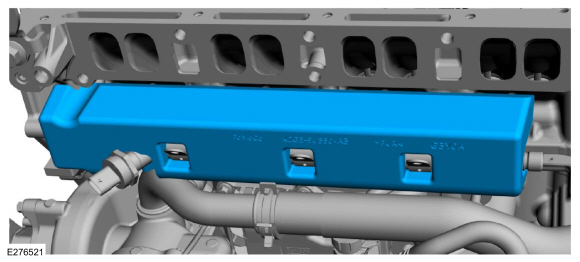
Remove the fuel rail insulator shield.
-
Remove the nuts and the CAC intake pipe bracket.
-
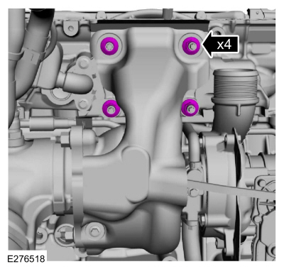
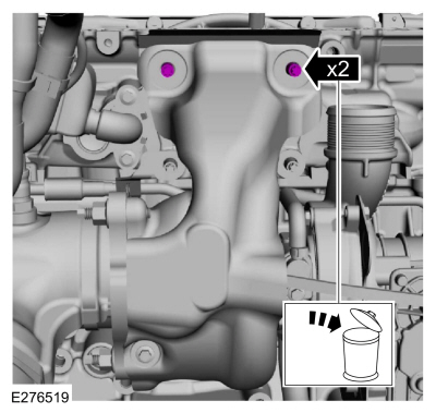
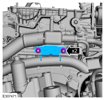
Remove the bolts, stud bolts and position the water outlet aside.
-
NOTE:
If the camshafts and valve tappets are to be reused,
mark the location of the valve tappets to make sure they are assembled
in their original positions.
Remove the valve tappets.
-
-
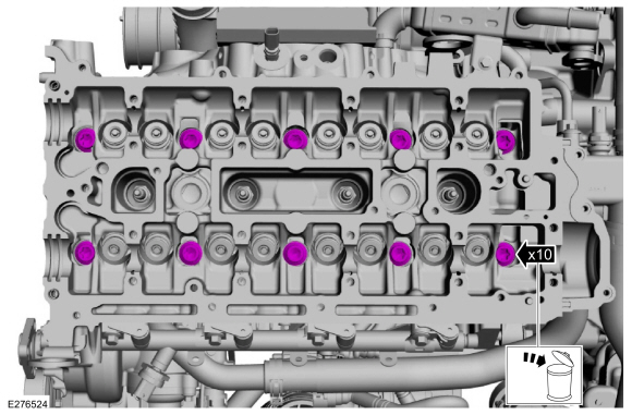
Remove the cylinder head bolts.
-
NOTICE:
When removing or installing the cylinder head, use
care to prevent excessive movement of the turbocharger. Excessive
movement may cause damage to the turbocharger oil return tube resulting
in an engine oil leak.
-
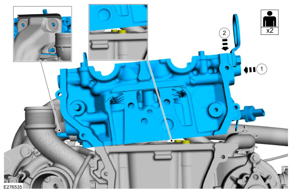
Lift the cylinder head to clear the locating dowels in the cylinder block.
-
Slide the cylinder head and studs out of the turbocharger and remove.
Click here to view a video version of this procedure.

-
-
Remove and discard the gasket.
-
Inspect and replace the studs if damaged.
-
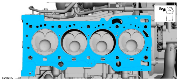
Remove and discard the cylinder head gasket.
-
NOTICE:
Do not use metal scrapers, wire brushes, power
abrasive discs or other abrasive means to clean the sealing surfaces.
These tools cause scratches and gouges that make leak paths. Use a
plastic scraping tool to remove all traces of the head gasket.
Clean the cylinder head sealing surfaces.
-
NOTICE:
Do not use metal scrapers, wire brushes, power
abrasive discs or other abrasive means to clean the sealing surfaces.
These tools cause scratches and gouges that make leak paths. Use a
plastic scraping tool to remove all traces of the head gasket.
NOTE:
Clean the cylinder head bolt holes in the cylinder
block. Make sure all coolant, oil or other foreign material is removed.
Clean the cylinder block sealing surfaces.
-
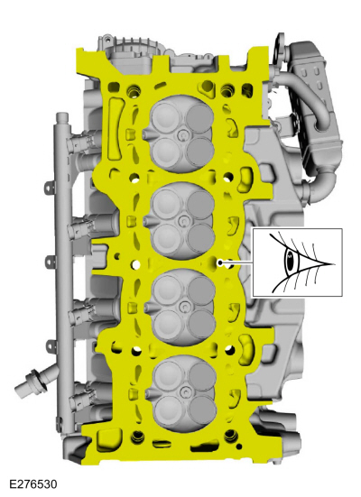
Inspect the cylinder head sealing surfaces.
-
-
Check the cylinder head distortion.
Refer to: Cylinder Head Distortion (303-00 Engine System - General Information, General Procedures).
-
Check the cylinder block distortion.
Refer to: Cylinder Block Distortion (303-00 Engine System - General Information, General Procedures).
-
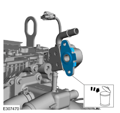
NOTE:
Replace gasket if damaged.
Inspect the coolant outlet gasket and replace as necessary.
Installation
-
Inspect the turbocharger or engine air intake system components and clean, if necessary.
-
-
If removed, install the lower studs.
Torque:
159 lb.in (18 Nm)
-
Install a new turbocharger gasket.
-
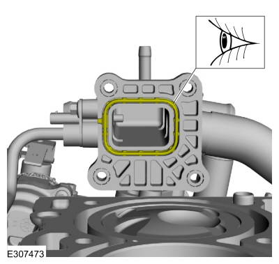
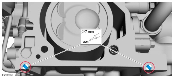
NOTICE:
Do not allow silicone sealant in or near the
high-pressure oil feed hole. Any restriction in the high-pressure oil
feed may result in engine damage.
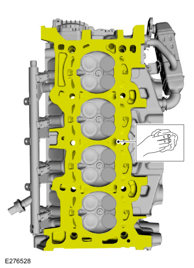
NOTE:
The cylinder head must be installed within 10 minutes of applying the sealant.
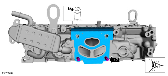
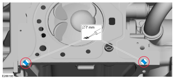
Apply a 7 mm (0.28 in) drop of silicone sealant at positions shown on the cylinder block.
Material: Motorcraft® High Performance Engine RTV Silicone
/ TA-357
(WSE-M4G323-A6)
-
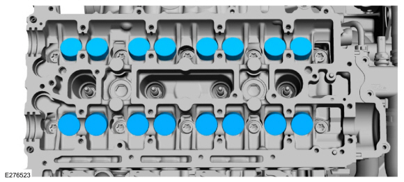
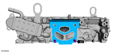
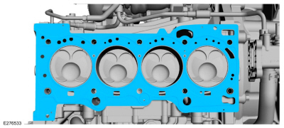
Install the new cylinder head gasket.
-
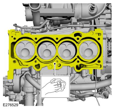
NOTICE:
Do not allow silicone sealant in or near the
high-pressure oil feed hole. Any restriction in the high-pressure oil
feed may result in engine damage.
NOTE:
The cylinder head must be installed within 10 minutes of applying the sealant.
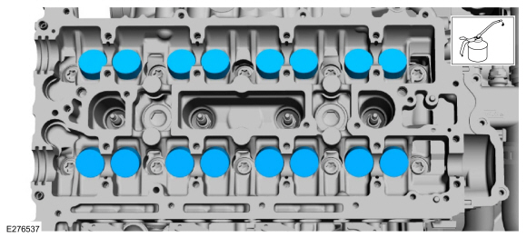
Apply a 7 mm (0.28 in) drop of silicone sealant at positions shown.
Material: Motorcraft® High Performance Engine RTV Silicone
/ TA-357
(WSE-M4G323-A6)
-
NOTICE:
When removing or installing the cylinder head, use
care to prevent excessive movement of the turbocharger. Excessive
movement may cause damage to the turbocharger oil return tube resulting
in an engine oil leak.
-
Slide the cylinder head and studs into the turbocharger.
-
Align the cylinder head to the locating dowels in the cylinder block and install.
Click here to view a video version of this procedure.
-
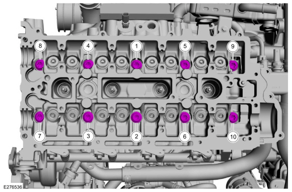
Install the new cylinder head bolts and tighten in sequence shown.
Torque:
Stage 1:
62 lb.in (7 Nm)
Stage 2:
133 lb.in (15 Nm)
Stage 3:
41 lb.ft (55 Nm)
Stage 4:
90°
Stage 5:
90°
-
NOTE:
Make sure that the components are installed to the position noted before removal.
Lubricate with clean engine oil and install the valve tappets.
-
Position the water outlet and install the stud bolts and bolts.
Torque:
97 lb.in (11 Nm)
-
Install the CAC intake pipe bracket and the nuts.
Torque:
44 lb.in (5 Nm)
-
Install the fuel rail insulator shield.
-
-
Install the harness and attach the wiring harness retainers.
-
Connect the fuel rail wiring harness electrical connectors.
-
Install the new upper cylinder head studs.
Torque:
159 lb.in (18 Nm)
-
-
Install the lower turbocharger nuts.
Torque:
39 lb.ft (53 Nm)
-
Install the upper turbocharger nuts.
Torque:
39 lb.ft (53 Nm)
-
Position the ground wire and install the bolt.
Torque:
106 lb.in (12 Nm)
-
Install the CAC pipe and tighten the clamp.
Torque:
27 lb.in (3 Nm)
-
Install a new EGR inlet tube gasket.
-
-
Install the EGR inlet tube assembly and the bolts.
Torque:
97 lb.in (11 Nm)
-
Install the stud bolt.
Torque:
97 lb.in (11 Nm)
-
Connect the exhaust manifold back pressure sensor, and the ECT sensor wiring harness electrical connectors.
-
Install the camshafts.
Refer to: Camshafts (303-01A Engine - 2.0L EcoBoost (177kW/240PS) – MI4, Removal and Installation).
-
Install the CAC intake pipe, nut and the bolts.
Torque:
44 lb.in (5 Nm)
-
Connect the transmission wiring harness connector and attach the retainers.
-
Install the manual control lever and the nut.
Torque:
106 lb.in (12 Nm)
-
-
Position back the manual park release cable and install the bolt.
Torque:
177 lb.in (20 Nm)
-
Connect the manual park release cable to the manual control lever.
-
-
Connect the coolant hoses.
Use the General Equipment: Hose Clamp Remover/Installer
-
Install the degas bottle coolant hose and attach the retainer.
Use the General Equipment: Hose Clamp Remover/Installer
-
Connect heater hose to the EGR cooler.
-
Attach the coolant hose retainers.
-
Position the LH front CAC tube and tighten the clamp.
Torque:
44 lb.in (5 Nm)
-
Install the CAC pipe and the clip.
-
Install the CAC tube and tighten the clamps.
Torque:
44 lb.in (5 Nm)
-
Connect the HO2S electrical connector and the wiring harness retainer.
-
Connect the CAC tube bypass valve electrical connector and wire retainer.
-
Install the intake manifold.
Refer to: Intake Manifold (303-01A Engine - 2.0L EcoBoost (177kW/240PS) – MI4, Removal and Installation).
-
-
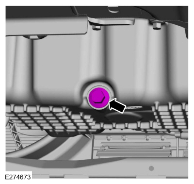
Remove the oil pan drain bolt and drain the engine oil.
Use the General Equipment: Oil Drain Equipment
-
Install the oil pan drain bolt.
Torque:
20 lb.ft (27 Nm)
-
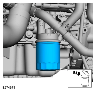
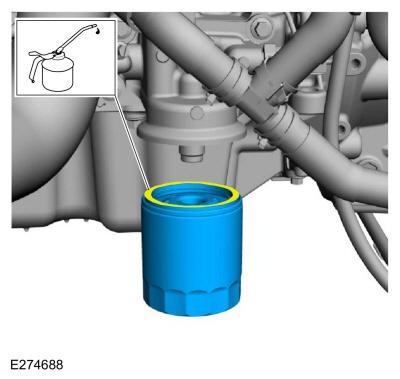
Remove and discard the engine oil filter.
Use the General Equipment: Oil Drain Equipment
-
Lubricate the oil filter seal with clean engine oil and install.
Torque:
Stage 1:
71 lb.in (8 Nm)
Stage 2:
180°
-
Fill the engine with clean engine oil.
Refer to: Specifications (303-01A Engine - 2.0L EcoBoost (177kW/240PS) – MI4, Specifications).
-
Install the battery tray.
Refer to: Battery Tray - 2.0L EcoBoost (177kW/240PS) – MI4/2.3L
EcoBoost (199kW/270PS) (414-01 Battery, Mounting and Cables, Removal and
Installation).
-
Pressurize the fuel system.
Refer to: Fuel System Pressure Release (310-00A Fuel System - General
Information - 2.0L EcoBoost (177kW/240PS) – MI4, General Procedures).
-
Fill the cooling system.
Refer to: Engine Cooling System Draining, Vacuum Filling and Bleeding
(303-03B Engine Cooling - 2.3L EcoBoost (199kW/270PS), General
Procedures).
-
Install the underbody shield and the retainers.
Torque:
13 lb.in (1.5 Nm)
Special Tool(s) /
General Equipment
303-328
(T88P-6701-B1)
Replacer, Rear SealTKIT-1988-FLMTKIT-1988-FTKIT-1988-LM
Oil Drain Equipment
Materials
Name
Specification
Motorcraft® High Performance Engine RTV SiliconeTA-357
WSE-M4G323-A6
Removal
Remove the flexplate...
Special Tool(s) /
General Equipment
303-096
(T74P-6150-A)
Installer, Camshaft Front Oil SealTKIT-2009TC-F
303-1521Alignment Tool, Crankshaft Position SensorTKIT-2010C-FLM
303-1685Alignment Tool, Camshaft
303-1689Holding Tool, Crank Damper
303-409
(T92C-6700-CH)
Remover, Crankshaft SealTKIT-1992-FH/FMH/FLMHTKIT-1993-LMH/MH
303-507Timing Peg, Crankshaft ..
Other information:
WARNING: Do not adjust the driver
seat or seat backrest when your vehicle is
moving. This may result in sudden seat
movement, causing the loss of control of
your vehicle.
WARNING: Do not place cargo or
any objects behind the seat backrest
before returning it to the original position.
Pull on the seat backrest to make sure that
it has fully latched after returning the seat
backrest to its ..
Extending the Remote Start Duration
To extend the engine running duration
during remote start, do the following:
Press the button on the remote
control.
Within three seconds, press the
button on the remote control.
Within three seconds, press the
button again.
Note: You can extend the engine running
duration to a maximum of 30 minutes.
Remotely Stopping the Engine
Press the button on the r..


 Removal and Installation - Crankshaft Rear Seal
 Removal and Installation - Engine Front Cover