Lincoln Corsair: Engine - 2.0L EcoBoost (177kW/240PS) – MI4 / Removal and Installation - Engine Front Cover
Special Tool(s) /
General Equipment
 |
303-096
(T74P-6150-A)
Installer, Camshaft Front Oil Seal
TKIT-2009TC-F |
 |
303-1521
Alignment Tool, Crankshaft Position Sensor
TKIT-2010C-FLM |
 |
303-1685
Alignment Tool, Camshaft |
 |
303-1689
Holding Tool, Crank Damper |
 |
303-409
(T92C-6700-CH)
Remover, Crankshaft Seal
TKIT-1992-FH/FMH/FLMH
TKIT-1993-LMH/MH |
 |
303-507
Timing Peg, Crankshaft TDC
TKIT-2001N-FLM
TKIT-2001N-ROW |
| Oil Drain Equipment |
Materials
| Name |
Specification |
Motorcraft® High Performance Engine RTV Silicone
TA-357 |
WSE-M4G323-A6
|
Removal
LHD AWD/LHD FWD
NOTICE:
Do not loosen or remove the crankshaft pulley bolt
without first installing the special tools as instructed in this
procedure. The crankshaft pulley and the crankshaft timing sprocket are
not keyed to the crankshaft. The crankshaft, the crankshaft sprocket and
the pulley are fitted together by friction. For that reason, the
crankshaft sprocket is also unfastened if the pulley bolt is loosened.
Before any repair requiring loosening or removal of the crankshaft
pulley bolt, the crankshaft and camshafts must be locked in place by the
special service tools, otherwise severe engine damage can occur.
NOTICE:
During engine repair procedures, cleanliness is
extremely important. All parts must be thoroughly cleaned and any
foreign material, including any material created while cleaning gasket
surfaces, that enters the oil passages, coolant passages or the oil pan,
can cause engine failure.
-
With the vehicle in NEUTRAL, position it on a hoist.
Refer to: Jacking and Lifting - Overview (100-02 Jacking and Lifting, Description and Operation).
-
Release the fuel system pressure.
Refer to: Fuel System Pressure Release (310-00A Fuel System - General
Information - 2.0L EcoBoost (177kW/240PS) – MI4, General Procedures).
-
Loosen the coolant pump pulley bolts.
-
Remove the following items:
-
Remove the accessory drive belt.
Refer to: Accessory Drive Belt (303-05A Accessory Drive - 2.0L EcoBoost (177kW/240PS) – MI4, Removal and Installation).
-
Remove the accessory drive belt tensioner.
Refer to: Accessory Drive Belt Tensioner (303-05A Accessory Drive -
2.0L EcoBoost (177kW/240PS) – MI4, Removal and Installation).
-
Remove the high-pressure fuel pump drive unit.
Refer to: High-Pressure Fuel Pump Drive Unit (303-04A Fuel Charging and
Controls - 2.0L EcoBoost (177kW/240PS) – MI4, Removal and
Installation).
-
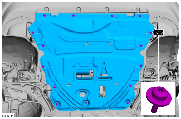
Remove the retainers and the underbody shield.
-
Remove the RH fender splash shield.
Refer to: Fender Splash Shield (501-02 Front End Body Panels, Removal and Installation).
LHD AWD
-
Remove the AWD RH halfshaft.
Refer to: Front Halfshaft RH - AWD (205-04 Front Drive Halfshafts, Removal and Installation).
-
Remove the bolts and the transfer case support bracket.
LHD FWD
-
Remove the FWD RH halfshaft.
Refer to: Front Halfshaft RH - 2.0L EcoBoost (177kW/240PS) – MI4, FWD
(205-04 Front Drive Halfshafts, Removal and Installation).
-
Remove the bolts and the halfshaft support bracket.
LHD AWD/LHD FWD
-
If equipped, release the tabs and remove the crankshaft pulley cover.
-
If equipped, inspect the 3 crankshaft pulley cover
tabs for damage, if damaged replace the crankshaft pulley cover.
-
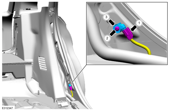
-
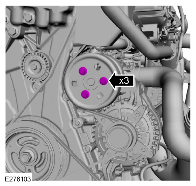
Disconnect the CKP sensor electrical connector.
-
Remove the bolts and the CKP sensor.
-
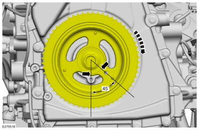
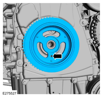
Turn the crankshaft clockwise until the No.1 piston is 45 degrees BTDC
using the guide holes on the engine front cover and the crankshaft
pulley.
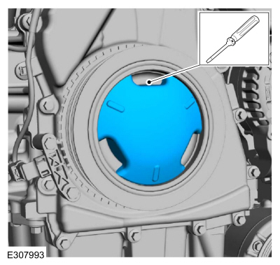
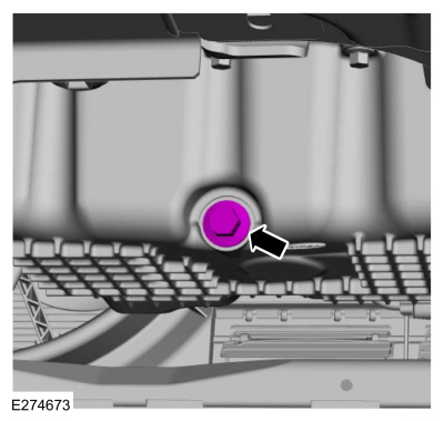
-
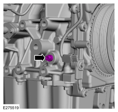
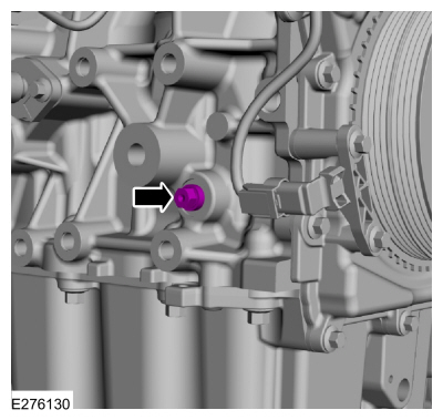
Remove the engine plug bolt.
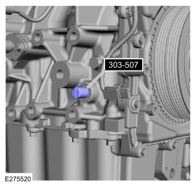
-
Install Special Service Tool: 303-507
Timing Peg, Crankshaft TDC.
-
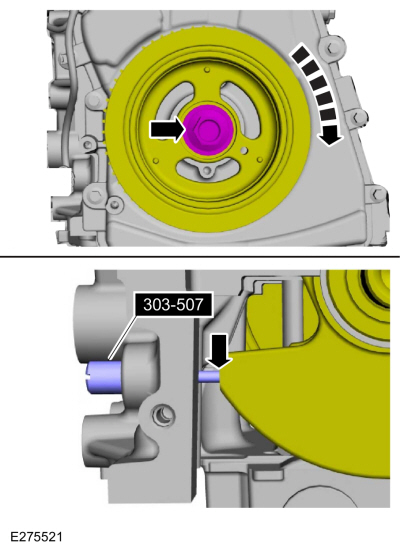
NOTE:
The Crankshaft TDC Timing Peg will contact the crankshaft and prevent
it from turning past TDC . However, the crankshaft can still be rotated
in the counterclockwise direction. The crankshaft must remain at the TDC
position during the crankshaft pulley removal and installation.
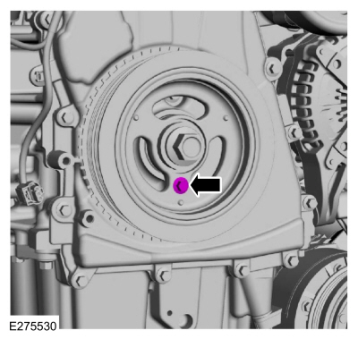
NOTE:
The engine front cover is removed from graphic for clarity.
Rotate the crankshaft clockwise until the contacts the special tool.
Use Special Service Tool: 303-507
Timing Peg, Crankshaft TDC.
-
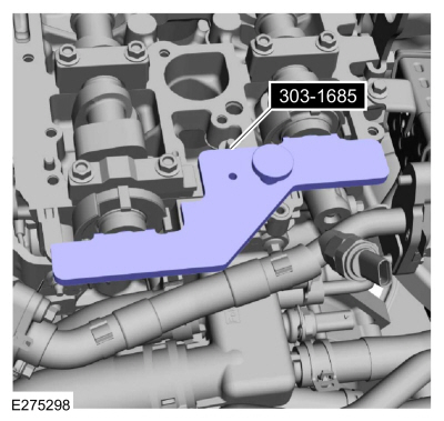
NOTICE:
The Camshaft Alignment Tool is for camshaft
alignment only. Using this tool to prevent engine rotation can result in
engine damage.
NOTE:
The camshaft timing slots are offset. If the Camshaft Alignment Tool cannot be installed, remove the TDC
Timing Peg and rotate the crankshaft three-fourths of a revolution
clockwise and repeat the previous 2 steps of this procedure.
Install Special Service Tool: 303-1685
Alignment Tool, Camshaft.
-
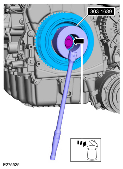
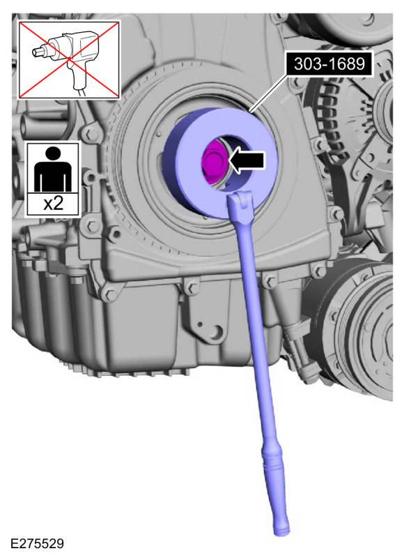
NOTICE:
The crankshaft must remain in the TDC
position during removal of the pulley bolt or damage to the engine can
occur. Therefore, the crankshaft pulley must be held in place with the
Crank Damper Holding Tool and the bolt should be removed using an air
impact wrench (1/2-in drive minimum).
-
Using the special tool, remove the bolt, washer and the crankshaft pulley.
Use Special Service Tool: 303-1689
Holding Tool, Crank Damper.
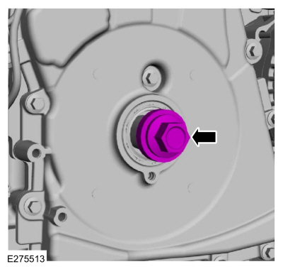
-
Install the old crankshaft pulley bolt.
-
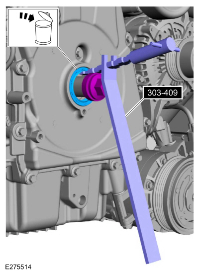
NOTICE:
Use care not to damage the engine front cover or the crankshaft when removing the seal.
Using the special tool, remove and discard the crankshaft front seal.
Use Special Service Tool: 303-409
(T92C-6700-CH)
Remover, Crankshaft Seal.
-
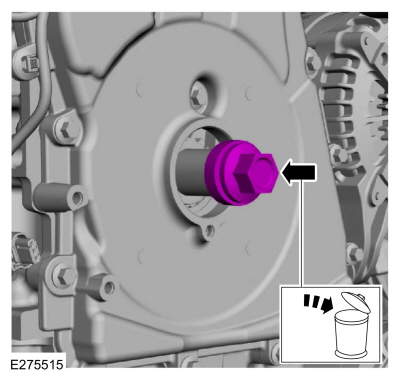
NOTE:
If necessary, retain the original crankshaft pulley bolt to use in other procedures.
Remove and discard the crankshaft pulley bolt.
-
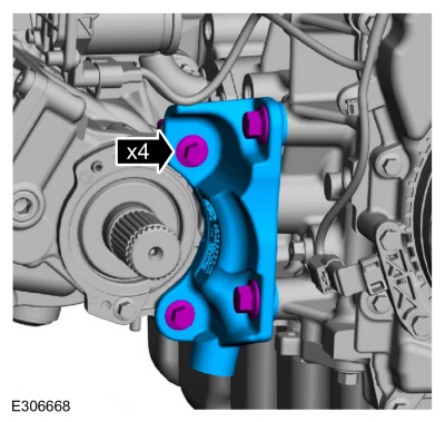
Remove the engine mount.
Refer to: Engine Mount (303-01A Engine - 2.0L EcoBoost (177kW/240PS) – MI4, Removal and Installation).
-
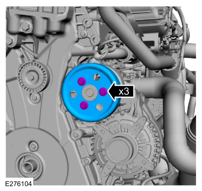
Remove the bolts and the coolant pump pulley.
-
Detach wiring harness retainers from the engine front cover and stud bolts.
-
Remove the fasteners and the engine front cover.
-
Clean and prepare the RTV sealing surface.
Refer to: RTV Sealing Surface Cleaning and Preparation (303-00 Engine System - General Information, General Procedures).
-
Clean and prepare the RTV sealing surface.
Refer to: RTV Sealing Surface Cleaning and Preparation (303-00 Engine System - General Information, General Procedures).
Installation
LHD AWD/LHD FWD
-
NOTE:
The engine front cover must be secured within 10
minutes of Silicone Gasket and Sealant application. If the engine front
cover is not secured within 10 minutes, the sealant must be removed and
the sealing area cleaned.
-
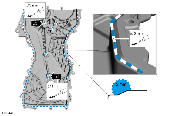
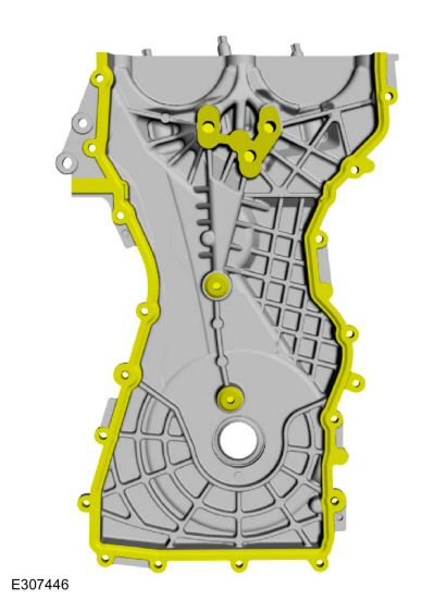
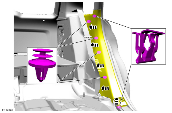
Apply a 3 mm (0.12 in) bead of silicone sealant on the 3 upper bosses, as shown.
Material: Motorcraft® High Performance Engine RTV Silicone
/ TA-357
(WSE-M4G323-A6)
-
Apply a 4 mm (0.16 in) bead of silicone sealant on the chamfer on the 2 lower bosses, as shown.
Material: Motorcraft® High Performance Engine RTV Silicone
/ TA-357
(WSE-M4G323-A6)
-
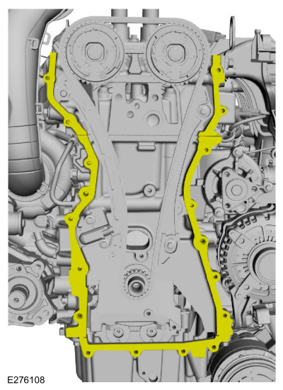
Apply a 5 mm (0.19 in) bead of silicone sealant on the chamfer, as shown.
Material: Motorcraft® High Performance Engine RTV Silicone
/ TA-357
(WSE-M4G323-A6)
 |
|
-
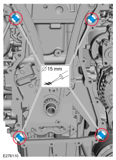
NOTE:
The engine front cover must be secured within 10
minutes of Silicone Gasket and Sealant application. If the engine front
cover is not secured within 10 minutes, the sealant must be removed and
the sealing area cleaned.
Apply a 15 mm (0.59 in) drop of silicone sealant at
the cylinder head-to-cylinder block and cylinder block-to-oil pan joint
areas.
Material: Motorcraft® High Performance Engine RTV Silicone
/ TA-357
(WSE-M4G323-A6)
-
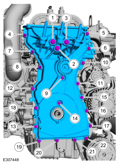
Install the engine front cover and the fasteners and tighten in the sequence shown.
Torque:
Bolts 1 - 3:
35 lb.ft (48 Nm)
Bolts 4 - 22:
97 lb.in (11 Nm)
-
Attach wiring harness retainers to the engine front cover and stud bolts.
-
Install the coolant pump pulley and bolts finger-tight.
-
Install the engine mount.
Refer to: Engine Mount (303-01B Engine - 2.3L EcoBoost (199kW/270PS), Removal and Installation).
-
-
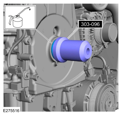
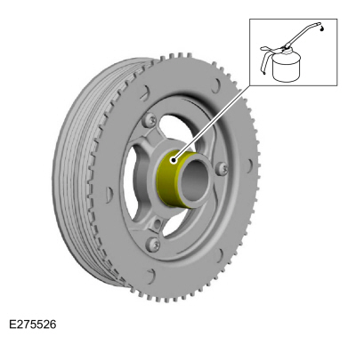
Lubricate the crankshaft front seal with clean engine oil.
-
Lubricate the crankshaft pulley with clean engine oil.
-
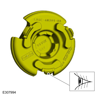
Position the crankshaft pulley onto the crankshaft with the access hole at the 6 o'clock position.
-
NOTE:
This step will correctly align the crankshaft pulley to the crankshaft.
Install an M6 bolt.
-
NOTICE:
The crankshaft must remain in the TDC
position during installation of the pulley bolt or damage to the
engine can occur. Therefore, the crankshaft pulley must be held in place
with the Crank Damper Holding Tool and the bolt should be installed
using hand tools only.
Using the special tool, install the new crankshaft bolt and washer and tighten.
Use Special Service Tool: 303-1689
Holding Tool, Crank Damper.
Torque:
Stage 1:
74 lb.ft (100 Nm)
Stage 2:
90°
-
Remove the M6 bolt.
-
NOTE:
Do not tighten the CKP sensor bolts at this time.
Install the CKP sensor and the bolts finger tight.
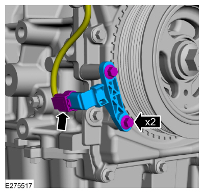
-
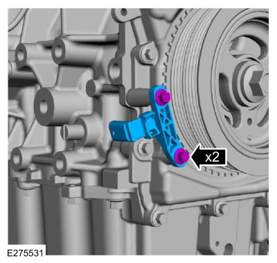
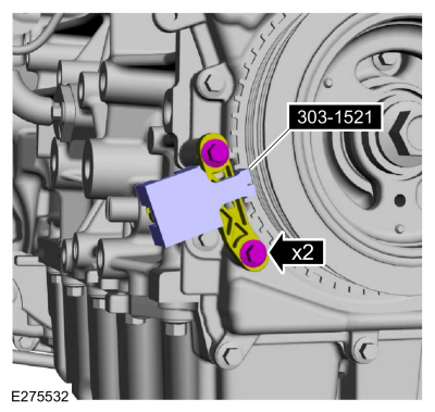
Install the special tool onto the CKP sensor and the tooth of the crankshaft pulley trigger wheel.
Use Special Service Tool: 303-1521
Alignment Tool, Crankshaft Position Sensor.
Torque:
97 lb.in (11 Nm)
-
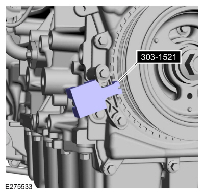
Remove Special Service Tool: 303-1521
Alignment Tool, Crankshaft Position Sensor.
-
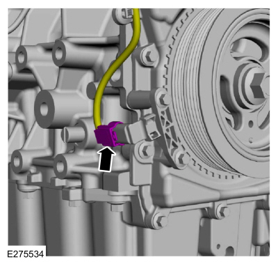
Connect the CKP sensor electrical connector.
-
Remove Special Service Tool: 303-507
Timing Peg, Crankshaft TDC.
-
Install the engine plug bolt.
Torque:
177 lb.in (20 Nm)
-
If equipped.
-
Align and insert 2 tabs of the crankshaft pulley
cover into the open spaces between the ribs of the crankcase pulley.
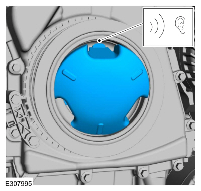
-
Press the third tab firmly into position until a snap is heard or felt.
-
Verify that the crankshaft pulley cover is securely in place.
-
Remove Special Service Tool: 303-1685
Alignment Tool, Camshaft.
LHD FWD
-
Install the halfshaft support bracket and the bolts.
Torque:
35 lb.ft (48 Nm)
-
Install the FWD RH halfshaft.
Refer to: Front Halfshaft RH - 2.0L EcoBoost (177kW/240PS) – MI4, FWD
(205-04 Front Drive Halfshafts, Removal and Installation).
LHD AWD
-
Install the transfer case support bracket and the bolts.
Torque:
35 lb.ft (48 Nm)
-
Install the AWD RH halfshaft.
Refer to: Front Halfshaft RH - AWD (205-04 Front Drive Halfshafts, Removal and Installation).
LHD AWD/LHD FWD
-
Install the following items:
-
Install the RH fender splash shield.
Refer to: Fender Splash Shield (501-02 Front End Body Panels, Removal and Installation).
-
Install the high-pressure fuel pump drive unit.
Refer to: High-Pressure Fuel Pump Drive Unit (303-04A Fuel Charging and
Controls - 2.0L EcoBoost (177kW/240PS) – MI4, Removal and
Installation).
-
Install the accessory drive belt tensioner.
Refer to: Accessory Drive Belt Tensioner (303-05A Accessory Drive -
2.0L EcoBoost (177kW/240PS) – MI4, Removal and Installation).
-
Install the accessory drive belt.
Refer to: Accessory Drive Belt (303-05A Accessory Drive - 2.0L EcoBoost (177kW/240PS) – MI4, Removal and Installation).
-
Tighten the coolant pump pulley bolts.
Torque:
18 lb.ft (25 Nm)
-
-
Remove the oil pan drain bolt and drain the engine oil.
Use the General Equipment: Oil Drain Equipment
-
Install the oil pan drain bolt.
Torque:
20 lb.ft (27 Nm)
-
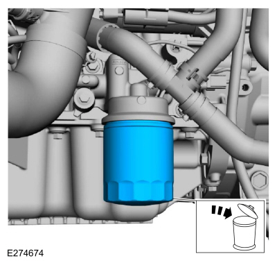
Remove and discard the engine oil filter.
Use the General Equipment: Oil Drain Equipment
-
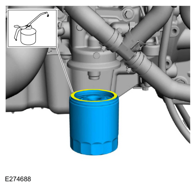
Lubricate the oil filter seal with clean engine oil and install.
Torque:
Stage 1:
71 lb.in (8 Nm)
Stage 2:
180°
-
Install the underbody shield and the retainers.
Torque:
13 lb.in (1.5 Nm)
-
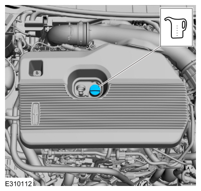
Fill the engine with clean engine oil.
Refer to: Specifications (303-01A Engine - 2.0L EcoBoost (177kW/240PS) – MI4, Specifications).
-
Pressurize the fuel system.
Refer to: Fuel System Pressure Release (310-00A Fuel System - General
Information - 2.0L EcoBoost (177kW/240PS) – MI4, General Procedures).
Special Tool(s) /
General Equipment
Oil Drain Equipment
Hose Clamp Remover/Installer
Materials
Name
Specification
Motorcraft® High Performance Engine RTV SiliconeTA-357
WSE-M4G323-A6
Removal
NOTICE:
Do not loosen or remove the crankshaft pulley bolt without
first installing the special tools as instructed in this procedure...
Special Tool(s) /
General Equipment
Trolley Jack
Wooden Block
Removal
With the vehicle in NEUTRAL, position it on a hoist.
Refer to: Jacking and Lifting - Overview (100-02 Jacking and Lifting, Description and Operation)...
Other information:
Special Tool(s) /
General Equipment
Interior Trim Remover
Removal
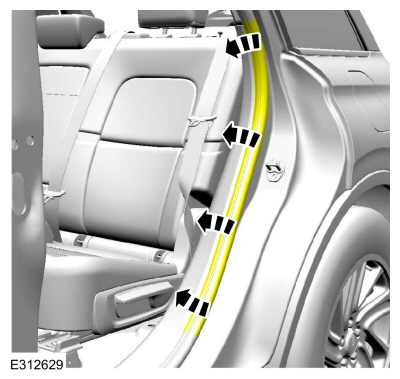
NOTE:
Left hand (LH) shown, right hand (RH) similar.
NOTE:
Removal steps in this procedure may contain installation details.
Remove the following items:
Remove the rear scuff plate trim panel...
Removal
NOTE:
LH (left-hand) side shown, RH (right-hand) side similar.
Remove the front door latch.
Refer to: Front Door Latch (501-14 Handles, Locks, Latches and Entry Systems, Removal and Installation).
NOTE:
This step is only necessary when installing a new component...


 Removal and Installation - Cylinder Head
 Removal and Installation - Engine Mount