Lincoln Corsair: Exhaust System - 2.0L EcoBoost (177kW/240PS) – MI4 / Removal and Installation - Catalytic Converter
Special Tool(s) / General Equipment
| Punch | |
| Copper Hammer |
Removal
NOTE: If the catalytic converter is not being replaced, the HO2S and the catalyst monitor sensor do not need to be removed from the catalytic converter. Disconnecting the electrical connectors is still necessary.
NOTE: Removal steps in this procedure may contain installation details.
All vehicles
-
With the vehicle in NEUTRAL, position it on a hoist.
Refer to: Jacking and Lifting - Overview (100-02 Jacking and Lifting, Description and Operation).
-
Remove the HO2S .
Refer to: Heated Oxygen Sensor (HO2S) (303-14A Electronic Engine Controls - 2.0L EcoBoost (177kW/240PS) – MI4, Removal and Installation).
-
Remove the catalyst monitor sensor.
Refer to: Catalyst Monitor Sensor (303-14A Electronic Engine Controls - 2.0L EcoBoost (177kW/240PS) – MI4, Removal and Installation).
-
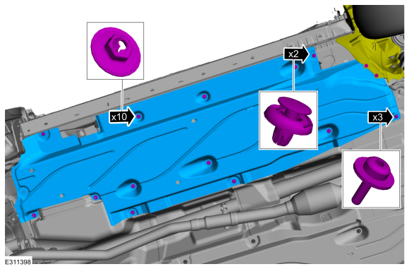
Remove the engine front undershield.
Refer to: Engine Front Undershield (501-02 Front End Body Panels, Removal and Installation).
-
-
Remove the push pin.
-
Remove the screws and position the RH wheel arch liner aside.
Torque: 22 lb.in (2.5 Nm)
-
Remove the stamped nuts and RH air deflector.
Torque: 22 lb.in (2.5 Nm)
-
Remove the push pin.
 |
-
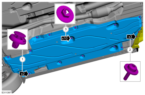
-
Remove the push pin.
-
Remove the screws and position the LH wheel arch liner aside.
Torque: 22 lb.in (2.5 Nm)
-
Remove the stamped nuts and LH air deflector.
Torque: 22 lb.in (2.5 Nm)
-
Remove the push pin.
 |
-
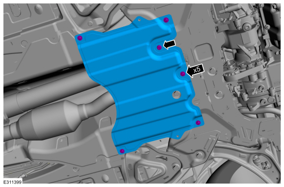
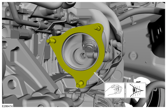
Remove the screws, trim pin and the heat shield.
Torque: 22 lb.in (2.5 Nm)
 |
-
Remove the muffler and tailpipe.
Refer to: Muffler and Tailpipe (309-00A Exhaust System - 2.0L EcoBoost (177kW/240PS) – MI4, Removal and Installation).
vehicles:
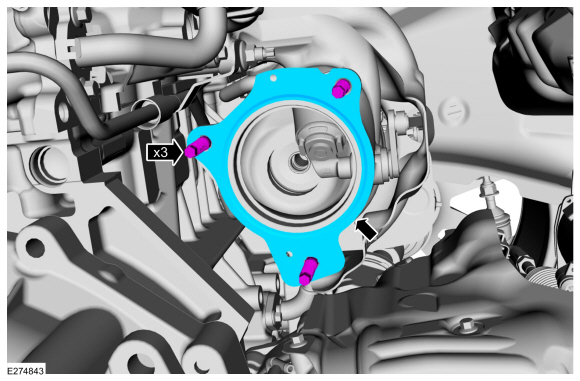
-
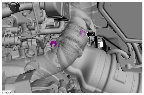
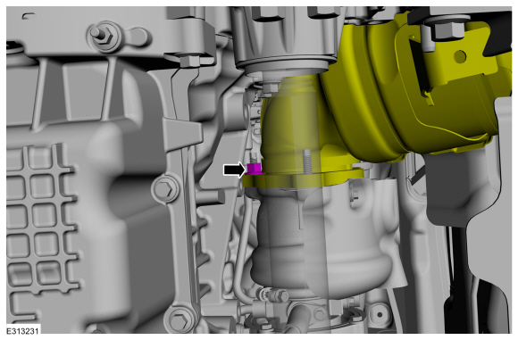
Remove and discard the catalytic converter flange nuts.
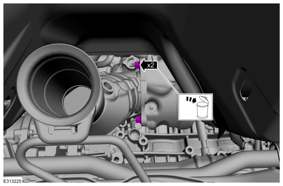 |
-
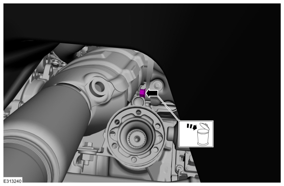
Remove and discard the catalytic converter flange nut.
 |
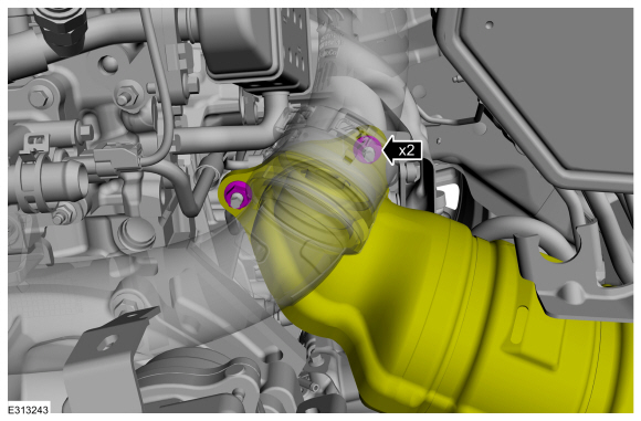
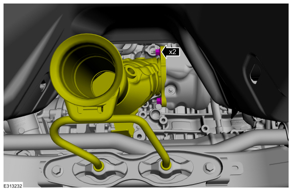
-
-
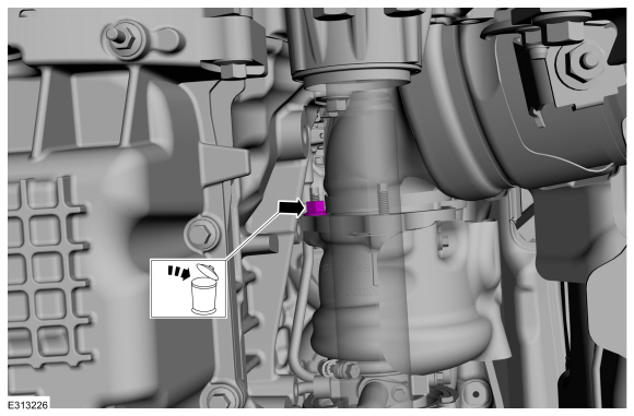
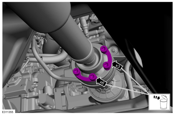
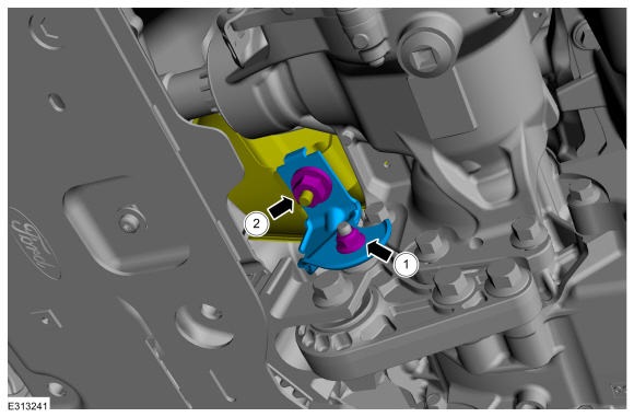
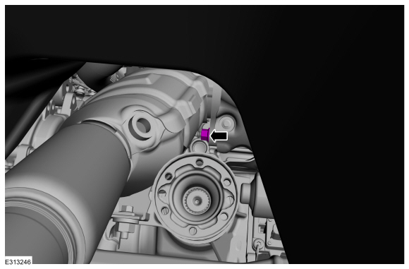
Remove the lower bracket nut.
-
Remove the PIA nut.
-
Remove the lower bracket nut.
 |
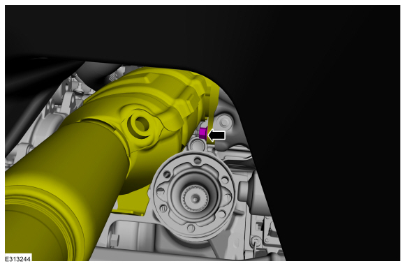
-
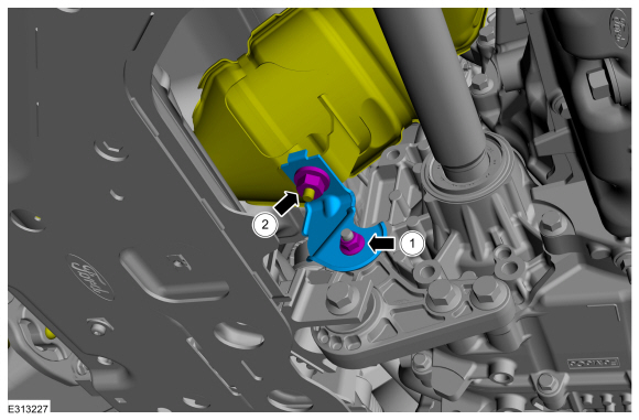
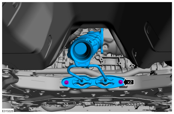
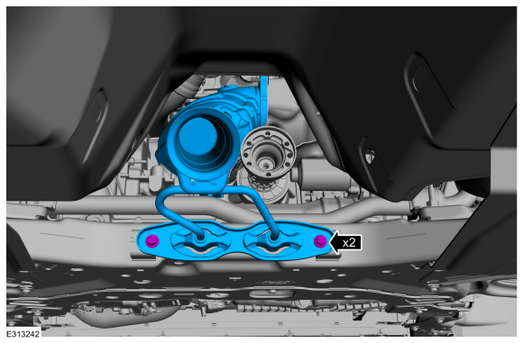
Remove the catalytic converter support bracket bolts and the catalytic converter.
 |
vehicles:
-
Remove the battery tray.
Refer to: Battery Tray - 2.0L EcoBoost (177kW/240PS) – MI4/2.3L EcoBoost (199kW/270PS) (414-01 Battery, Mounting and Cables, Removal and Installation).
-
Remove and discard the catalytic converter flange nuts.
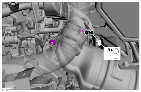 |
-
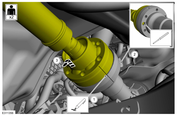
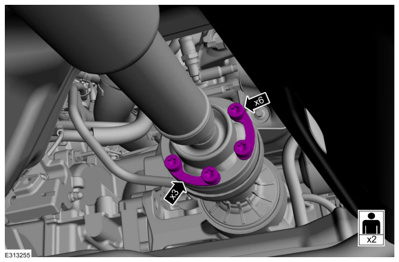
Remove and discard the driveshaft to PTU bolts and the retaining straps.
 |
-
-
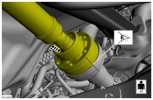
Index-mark the driveshaft and PTU flange.
-
NOTICE: Do not remove driveshaft from the PTU flange by pulling on the driveshaft tube. Damage to the CV-joint can result.
NOTE: This is a tight fit, do not remove the CV flange from the PTU flange at this time.
Using general equipment, separate the driveshaft from the PTU flange.
Use the General Equipment: Punch
Use the General Equipment: Copper Hammer
-
Disconnect the driveshaft from the PTU flange
and position it aside. Use mechanics wire to support the driveshaft.
-
Index-mark the driveshaft and PTU flange.
 |
-
Remove and discard the catalytic converter flange nut.
 |
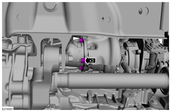
-
-
Remove the lower bracket nut.
-
Remove the PIA nut.
-
Remove the lower bracket nut.
 |
-
Remove the catalytic converter support bracket bolts and the catalytic converter.
 |
All vehicles
-
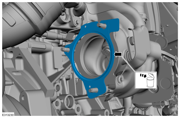
Remove and discard the gasket.
 |
-
NOTE: The following step is only required if the components are being replaced with new items.
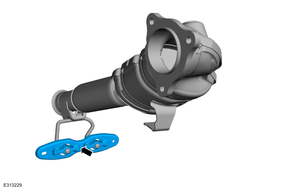
Remove the isolator bracket assembly.
 |
Installation
All vehicles
-
Clean all the exhaust connections before reassembly.
-
Clean and Inspect the gasket surface and the studs.
 |
-
NOTE: Make sure that new gasket is installed.
NOTE: Install the new studs if necessary.
Install a new gasket.
Torque: 18 lb.ft (25 Nm)
 |
-
NOTE: The following step is only required if the components are being replaced with new items.
Install the isolator bracket assembly.
|
vehicles:
-
Install the catalytic converter into the vehicle and install the support bracket bolts.
Torque: 18 lb.ft (25 Nm)
|
-
NOTE: The nuts are only finger tight at this step.
Install the catalytic converter flange nuts.
 |
-
NOTE: The nut is only finger tight at this step.
Install the catalytic converter flange nut.
 |
-
-
Install the lower bracket nut.
Torque: 35 lb.ft (47.5 Nm)
-
Install the PIA nut.
Torque: 35 lb.ft (47.5 Nm)
-
Install the lower bracket nut.
|
-
NOTE: Make sure that new nuts are installed.
Tighten the catalytic converter flange nuts.
Torque: 35 lb.ft (47.5 Nm)
 |
-
NOTE: Make sure that a new nut is installed.
Tighten the catalytic converter flange nut.
Torque: 35 lb.ft (47.5 Nm)
 |
-
NOTE: Make sure that the component aligns with the installation mark.
Position the drive shaft in the installed position and make sure it aligns with the index marks.
 |
-
NOTE: Make sure that new bolts and retaining straps are installed.
Install new retaining straps and bolts.
Torque: 26 lb.ft (35 Nm)
 |
-
Install the battery tray.
Refer to: Battery Tray - 2.0L EcoBoost (177kW/240PS) – MI4/2.3L EcoBoost (199kW/270PS) (414-01 Battery, Mounting and Cables, Removal and Installation).
vehicles:
-
Position the catalytic converter back in the vehicle and install the bolts.
Torque: 18 lb.ft (25 Nm)
|
-
NOTE: The nut is only finger tight at this step.
Install the catalytic converter flange nut.
 |
-
NOTE: The nuts are only finger tight at this step.
Install the catalytic converter flange nuts.
 |
-
-
Install the lower bracket nut.
Torque: 35 lb.ft (47.5 Nm)
-
Install the PIA nut.
Torque: 35 lb.ft (47.5 Nm)
-
Install the lower bracket nut.
|
-
NOTE: Make sure that new nuts are installed.
Tighten the catalytic converter flange nuts.
Torque: 35 lb.ft (47.5 Nm)
 |
All vehicles
-
To install, reverse the removal procedure.
-
Check the exhaust system for leaks.
 Diagnosis and Testing - Exhaust System
Global Customer Symptom Code (GCSC) Chart
Diagnostics in this manual assume a certain skill level and knowledge of Ford-specific diagnostic practices...

Other information:
Lincoln Corsair 2020-2026 Owners Manual: Capacities and Specifications - 2.3L
Use oil and fluid that meets the defined specification and viscosity grade. If you do not use oil and fluid that meets the defined specification and viscosity grade, it could result in: Component damage that your vehicle warranty does not cover. Longer engine cranking periods. Increased emission levels. Reduced engine performance. Reduced fuel economy. Reduced brake performance. Air C..
Lincoln Corsair 2020-2026 Service Manual: Removal and Installation - Cylinder Head Temperature 2 (CHT2) Sensor
Materials Name Specification Motorcraft® Silicone Brake Caliper Grease and Dielectric CompoundXG-3-A ESA-M1C200-AESE-M1C171-A Removal NOTE: Removal steps in this procedure may contain installation details. NOTICE: Do not pull the engine appearance cover forward or sideways to remove. Failure to press straight upward on the underside of the cover at the a..
Categories
- Manuals Home
- 1st Generation Lincoln Corsair Owners Manual
- 1st Generation Lincoln Corsair Service Manual
- Automatic Transmission - 8-Speed Automatic Transmission – 8F35/8F40
- Technical Specifications
- Auto-Start-Stop
- New on site
- Most important about car
Autowipers (IF EQUIPPED)
Wet or winter driving conditions with ice, snow or salty road mist can cause inconsistent and unexpected wiping or smearing.