Lincoln Corsair: Electronic Engine Controls - 2.0L EcoBoost (177kW/240PS) – MI4 / Removal and Installation - Camshaft Position (CMP) Sensor
Special Tool(s) / General Equipment
| Side Cutter Pliers | |
| Hose Clamp Remover/Installer |
Materials
| Name | Specification |
|---|---|
| Motorcraft® Silicone Brake Caliper Grease and Dielectric Compound XG-3-A |
ESA-M1C200-A ESE-M1C171-A |
Removal
NOTICE: The turbocharger compressor vanes can be damaged by even the smallest particles. When removing any turbocharger or engine air intake system component, ensure that no debris enters the system. Failure to do so may result in damage to the turbocharger.
NOTE: Removal steps in this procedure may contain installation details.
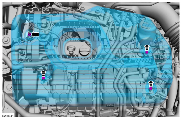
Right Hand Camshaft Position (CMP) Sensor
-
NOTICE: Do not pull the engine appearance cover forward or sideways to remove. Failure to press straight upward on the underside of the cover at the attachment points may result in damage to the cover or engine components.
-
Remove the engine appearance cover nut.
-
Place your hand under the engine appearance
cover at each grommet location and pull straight up to release each
grommet from the studs.
-
After all of the grommets have been released
from the studs, remove the appearance cover from the engine.
-
Remove the engine appearance cover nut.
 |
-
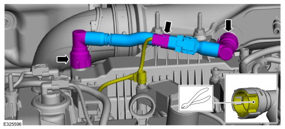
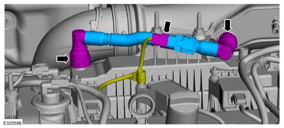
NOTE: The crankcase vent tube may have either a permanent or quick connect connector at one or both ends. If the tube needs to be removed for any reason, the permanent connector(s) must be cut to remove the tube. The tube will then need to be replaced.
NOTE: If the crankcase vent tube is replaced, the replacement part may not come with a crankcase pressure sensor. If so, the PCM will need to be reprogrammed.
-
If equipped, disconnect the wiring harness electrical connector.
-
If necessary, cut the lock tab.
Use the General Equipment: Side Cutter Pliers
-
If either crankcase vent tube connector was cut, remove and discard the crankcase vent tube.
-
If equipped, disconnect the wiring harness electrical connector.
 |
-
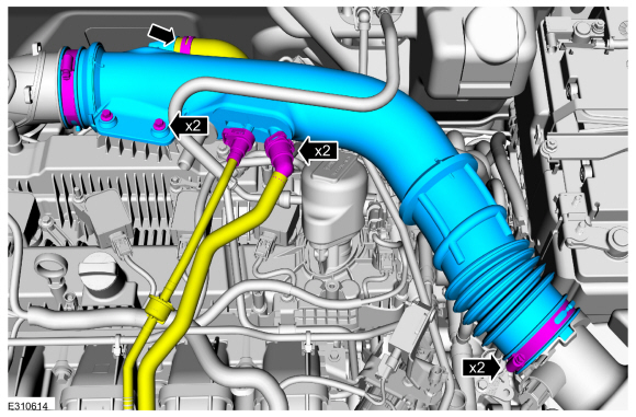
Remove the air cleaner outlet pipe.
-
Disconnect the vent tubes.
Refer to: Quick Release Coupling (310-00A Fuel System - General Information - 2.0L EcoBoost (177kW/240PS) – MI4, General Procedures).
-
Loosen the air cleaner outlet pipe clamps.
Torque: 44 lb.in (5 Nm)
-
Loosen the clamp and position aside the air bypass hose.
Use the General Equipment: Hose Clamp Remover/Installer
-
Remove the bolts and the air cleaner outlet tube.
Torque: 62 lb.in (7 Nm)
-
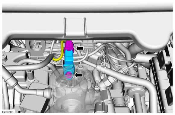
Disconnect the vent tubes.
 |
-
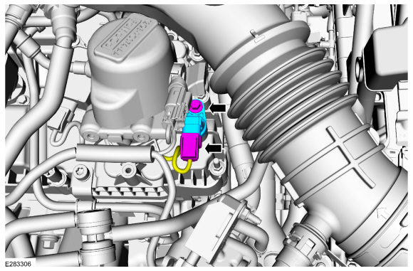
Disconnect the electrical connector, remove the retainer and the CMP sensor.
Torque: 62 lb.in (7 Nm)
 |
Left Hand Camshaft Position (CMP) Sensor
-
NOTICE: Do not pull the engine appearance cover forward or sideways to remove. Failure to press straight upward on the underside of the cover at the attachment points may result in damage to the cover or engine components.
-
Remove the engine appearance cover nut.
-
Place your hand under the engine appearance
cover at each grommet location and pull straight up to release each
grommet from the studs.
-
After all of the grommets have been released
from the studs, remove the appearance cover from the engine.
-
Remove the engine appearance cover nut.
|
-
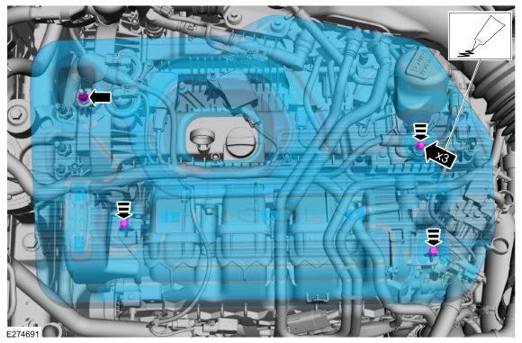
Disconnect the electrical connector, remove the retainer and the CMP sensor.
Torque: 62 lb.in (7 Nm)
 |
Installation
-
To install, reverse the removal procedure.
-
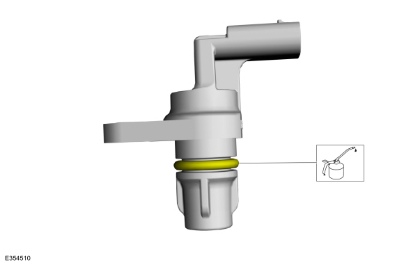
Lubricate the CMP sensor with clean engine oil.
 |
-
-
Install the new crankcase vent tube.
-
If the replacement crankcase vent tube part comes with no crankcase pressure sensor, reprogram the PCM .
Refer to: Module Programming (418-01 Module Configuration, General Procedures).
-
If the replacement crankcase vent tube came without a
crankcase pressure sensor, tape the wiring harness electrical connector
back to the wiring harness.
-
If the replacement crankcase vent tube comes with a
crankcase pressure sensor, connect the wiring harness electrical
connector.
-
Install the new crankcase vent tube.
 |
-
-
NOTE: Lubricating the grommets with silicone grease aids in the installation of the engine appearance cover, and any future removal and installation of the cover.
Lubricate each grommet with silicone grease.
Material: Motorcraft® Silicone Brake Caliper Grease and Dielectric Compound / XG-3-A (ESA-M1C200-A) (ESE-M1C171-A)
-
If the engine appearance cover stud bolt is loosened
or removed, it must be installed/tightened into the valve cover.
Torque: 62 lb.in (7 Nm)
-
Position the engine appearance cover onto the engine with the grommets aligned with the studs.
-
Press down on the engine appearance cover at each grommet location to attach the grommets onto the studs.
-
Install the engine appearance cover nut.
Torque: 44 lb.in (5 Nm)
-
 |
 Removal and Installation - Boost Pressure Sensor
Removal
NOTE:
Removal steps in this procedure may contain installation details.
NOTICE:
Do not pull the engine appearance cover forward or
sideways to remove...
 Removal and Installation - Catalyst Monitor Sensor
Special Tool(s) /
General Equipment
303-476
(T94P-9472-A)
Socket, Exhaust Gas Oxygen SensorTKIT-1994-LM/MTKIT-1994-FTKIT-1994-FLM/FM
Materials
Name
Specification
Motorcraft® High Temperature Nickel Anti-Seize LubricantXL-2
-
Motorcraft® Penetrating and Lock LubricantXL-1
-
Removal
NOTE:
Removal steps in this procedure may contain installation..
Other information:
Lincoln Corsair 2020-2024 Service Manual: Description and Operation - Transmission Description - Overview
Overview This automatic transmission is a 8-speed transmission with electronic shift control. It is designed for operation in a transverse powertrain for FWD and AWD vehicles. This transmission includes: Torque converter with converter clutch Eight forward speeds Four planetary gearsets One hydraulic SOWC Five friction clutches Mai..
Lincoln Corsair 2020-2024 Service Manual: Removal and Installation - Wheel Knuckle
Special Tool(s) / General Equipment 204-161 (T97P-1175-A) Installer, HalfshaftTKIT-1997-LM2TKIT-1997-F/FM2TKIT-1997-FLM2 205-D070 (D93P-1175-B) Remover, Front Wheel Hub Tie Rod End Remover Removal NOTICE: Suspension fasteners are critical parts that affect the performance of vital components and systems. Failure of these fasteners may result in major service expe..
Categories
- Manuals Home
- 1st Generation Lincoln Corsair Owners Manual
- 1st Generation Lincoln Corsair Service Manual
- Keyless Entry Settings
- Warning Lamps and Indicators
- Opening and Closing the Hood
- New on site
- Most important about car
Keyless Starting
Note: The keyless starting system may not function if the key is close to metal objects or electronic devices such as cellular phones.
Note: A valid key must be located inside your vehicle to switch the ignition on and start the engine.
Ignition Modes