Lincoln Corsair: Electronic Engine Controls - 2.0L EcoBoost (177kW/240PS) – MI4 / Removal and Installation - Boost Pressure Sensor
Lincoln Corsair 2020-2026 Service Manual / Powertrain / Engine / Electronic Engine Controls - 2.0L EcoBoost (177kW/240PS) – MI4 / Removal and Installation - Boost Pressure Sensor
Removal
NOTE: Removal steps in this procedure may contain installation details.
-
NOTICE: Do not pull the engine appearance cover forward or sideways to remove. Failure to press straight upward on the underside of the cover at the attachment points may result in damage to the cover or engine components.
-
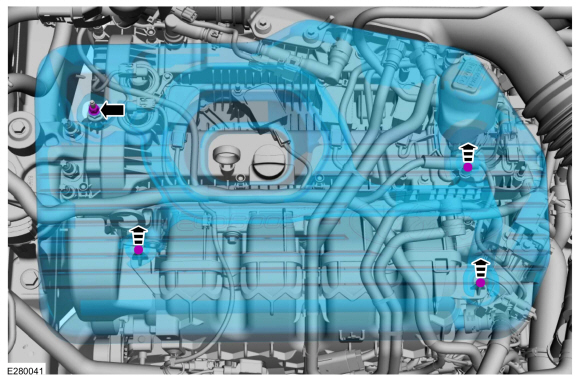
Remove the engine appearance cover nut.
Torque: 42 lb.in (4.8 Nm)
-
Place your hand under the engine appearance cover at
each grommet location and pull straight up to release each grommet from
the studs.
-
After all of the grommets have been released from
the studs, remove the appearance cover from the engine. If the engine
appearance cover stud bolt is loosened or removed, it must be
installed/tightened into the valve cover.
Torque: 62 lb.in (7 Nm)
-
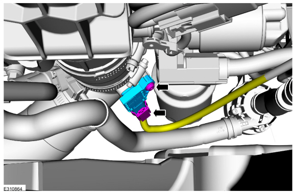
Remove the engine appearance cover nut.
 |
-
Disconnect the electrical connector, remove retainer and the turbocharger boost pressure sensor.
Torque: 44 lb.in (5.0 Nm)
 |
Installation
-
To install, reverse the removal procedure.
 Diagnosis and Testing - Variable Camshaft Timing (VCT) System
Diagnostic Trouble Code (DTC) Chart
Diagnostics in this manual assume a certain skill level and knowledge of Ford-specific diagnostic practices.REFER to: Diagnostic Methods (100-00 General Information, Description and Operation)...
 Removal and Installation - Camshaft Position (CMP) Sensor
Special Tool(s) /
General Equipment
Side Cutter Pliers
Hose Clamp Remover/Installer
Materials
Name
Specification
Motorcraft® Silicone Brake Caliper Grease and Dielectric CompoundXG-3-A
ESA-M1C200-AESE-M1C171-A
Removal
NOTICE:
The turbocharger compressor vanes can be damaged by even the
smallest particles...
Other information:
Lincoln Corsair 2020-2026 Service Manual: Removal and Installation - Thermostat
Materials Name Specification Motorcraft® Silicone Brake Caliper Grease and Dielectric CompoundXG-3-A ESA-M1C200-AESE-M1C171-A Removal NOTE: Removal steps in this procedure may contain installation details. Drain the cooling system...
Lincoln Corsair 2020-2026 Owners Manual: Tire Pressure Monitoring System Sensors - Vehicles With: 433 MHz Sensors
Argentina Brazil Djibouti European Union EU Ghana Jordan Mauritania Mexico Moldova Morocco Nigeria Oman Pakistan Paraguay NR: 2018-06-I-000224 Philippines Russia Serbia Singapore South Africa South Korea R-CRM-SRD-AG2SM4 Taiwan Ukraine United Arab Emirates (U...
Categories
- Manuals Home
- 1st Generation Lincoln Corsair Owners Manual
- 1st Generation Lincoln Corsair Service Manual
- Technical Specifications
- Selecting a Drive Mode. DRIVE MODES
- Interior Lamps
- New on site
- Most important about car
360 Degree Camera Cameras
Locating the Rear View Camera

The rear view camera is on the tailgate.
Locating the Front View Camera
Copyright © 2026 www.licorsair.com