Lincoln Corsair: Glass, Frames and Mechanisms / General Procedures - Heated Window Grid Wire Repair
Materials
| Name | Specification |
|---|---|
| Motorcraft® Ultra-Clear Spray Glass Cleaner ZC-23 |
ESR-M14P5-A |
| Motorcraft® Rear Window Defroster Repair PM-11 |
WSB-M4J58-B |
| Motorcraft® Lacquer Touch-Up Paint PMPC-19500-XXXXA, PMPM-19500-XXXXG, PMPP-19500-XXXXA |
ESR-M2P100-C |
Inspection
-
Using a bright lamp in the vehicle, inspect the grid
wire from the exterior. A broken grid wire appears as a brown spot.
-
Run the engine at idle. Activate the rear window defrost switch. The indicator light should come on.
-
Working in the vehicle with a voltmeter, contact the
broad red-brown stripes of the rear glass window (positive lead to B+
side and the negative lead to ground side). The meter should read 10-13
volts. A lower voltage reading indicates a loose ground connection.
-
Contact a good ground point with the negative lead of the meter. The voltage reading should not change.
-
With the negative lead of the meter grounded, touch each
grid line of the heated rear window glass at its midpoint with the
positive lead. A reading of approximately 6 volts indicates the line is
good. A reading of 0 volt indicates the line is broken between the
midpoint and the B+ side of the grid line. A reading of 12 volts
indicates the circuit is broken between the midpoint of the grid line
and ground.
-
Pinpointing the exact position of the break can be
accomplished (if the voltmeter reads 0 volt when the midpoint of the
grid line is touched with the positive lead of the voltmeter) by moving
the positive lead of the voltmeter toward the B+ side of the grid line
and touching the grid line until the voltmeter reads 12 volts. If the
voltmeter reads 12 volts when the midpoint of the grid line is touched
with the positive lead of the voltmeter, simply move the positive lead
of the voltmeter toward the ground connection of the grid line and touch
the grid line until the voltmeter reads 0 volt.
Repair
-
NOTE: The antenna and heated window grid line material is not embedded into the glass, but is baked to the glass surface and consequently can be scraped off. An undamaged grid line has small ridges that project above the surface of the glass and can easily be felt when running a fingernail across them. Antenna and heated window grid lines that have been razor bladed will feel smooth when a fingernail is dragged across the affected area. Inoperative heated window grid lines may appear to the eye to be undamaged due to residue remaining on the glass and require diagnosis with a voltmeter or 12V test lamp.
Bring the vehicle up to a room temperature of at least 16°C (60.8°F) or above.
-
NOTICE: Do not use scrapers, sharp instruments or abrasive window cleaners on the interior surface of the rear window glass as this may cause damage to the antenna and heated window grid lines.
Clean the entire antenna and heated window grid line repair area with glass cleaner and 0000 steel wool to remove all dirt, wax, grease, oil or other foreign material.
Material: Motorcraft® Ultra-Clear Spray Glass Cleaner / ZC-23 (ESR-M14P5-A)
-
Mark the location of the antenna or heated window grid break on the exterior of the rear window glass.
-
Using a polypropylene film fine line tape, mask the area
directly above and below the antenna or heated window grid break
extending the tape 26 mm (1.0236 in) beyond the concern area in both
directions. The break area should be at the center of the mask.
Polypropylene Film Fine Line Tape (commercially available).
.jpg) |
-
NOTE: If the brown layer is not broken or missing, apply only the silver grid repair compound to the break. If both the brown and silver layers of the antenna or heated window grid are broken or missing, apply a coating of the lacquer touch-up paint across the break in the grid line prior to applying the rear window defroster repair compound. Do not overlap the silver grid line with the paint. Several applications may be necessary to achieve a color match.
NOTE: Allow at least 5 minutes of drying time between applications for the touch-up paint or the silver repair coating. Applying fewer coats or not allowing adequate drying time between coats produces repaired resistance that is greater than Original Equipment Manufacturer (OEM) resistance, resulting in poor defrost performance and excessive localized heating.
Apply the repair coating to the antenna or heated window grid break area in several smooth, continuous strokes. Extend the silver repair coating at least 6.35 mm (0.25 in) on both sides of the break area. Apply a minimum of 6 applications of the grid repair compound. Polypropylene Film Fine Line Tape (commercially available)
Material: Motorcraft® Rear Window Defroster Repair / PM-11 (WSB-M4J58-B)
Material: Motorcraft® Lacquer Touch-Up Paint / PMPC-19500-XXXXA, PMPM-19500-XXXXG, PMPP-19500-XXXXA (ESR-M2P100-C)
.jpg) |
-
NOTE: The repair coating air dries in approximately one minute and can be energized after 5 minutes. Optimum adhesion occurs after approximately 24 hours.
Allow the repair area to dry completely and remove the mask.
.jpg) |
-
NOTICE: Be careful not to damage the antenna or heated window grid line with the razor blade. If this occurs, additional repair may be necessary.
Remove any excess repair compound above or below the antenna or heated window grid line with a razor blade.
-
NOTE: The interior side of the antenna or heated grid lines are not painted, but due to the silver tarnishing tend to change the grid to a gold or brown color. The repair area will be bright silver and also tarnish over time to match the rest of the antenna or heated window grid.
Test the system for normal operation.

 General Procedures - Lead Terminal Repair
Materials
Name
Specification
Motorcraft® Ultra-Clear Spray Glass CleanerZC-23
ESR-M14P5-A
Repair
Bring the vehicle up to at least the specified room temperature or above...
Other information:
Lincoln Corsair 2020-2026 Owners Manual: Emission Law
WARNING: Do not remove or alter the original equipment floor covering or insulation between it and the metal floor of the vehicle. The floor covering and insulation protect occupants of the vehicle from the engine and exhaust system heat and noise...
Lincoln Corsair 2020-2026 Service Manual: General Procedures - Valve Guide Inner Diameter
Check NOTE: Refer to the appropriate Section 303-01 for the specification. NOTE: Valve guides tend to wear in an hourglass pattern. The ball gauge can be inserted into the combustion chamber side of the valve guide, if necessary. Use a ball gauge to determine the inside diameter of the valve guides in 2 directions at the top, middle and bottom of the valve guide...
Categories
- Manuals Home
- 1st Generation Lincoln Corsair Owners Manual
- 1st Generation Lincoln Corsair Service Manual
- Fuel Quality - Gasoline
- Programming the Garage Door Opener to Your Garage Door Opener Motor
- Refueling - Gasoline
- New on site
- Most important about car
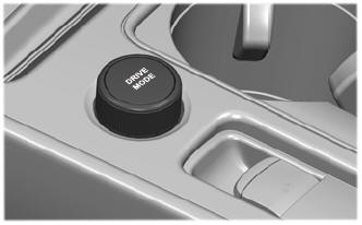
Selecting a Drive Mode. DRIVE MODES
Selecting a Drive Mode
Note: Drive mode changes may not be available when the ignition is off.