Lincoln Corsair: Engine - 2.0L EcoBoost (177kW/240PS) – MI4 / Disassembly - Engine
Special Tool(s) /
General Equipment
 |
205-153
(T80T-4000-W)
Handle |
 |
303-1685
Alignment Tool, Camshaft |
 |
303-1687
Installer, VCT Solenoid Seal |
 |
303-1689
Holding Tool, Crank Damper |
 |
303-409
(T92C-6700-CH)
Remover, Crankshaft Seal
TKIT-1992-FH/FMH/FLMH
TKIT-1993-LMH/MH |
 |
303-507
Timing Peg, Crankshaft TDC
TKIT-2001N-FLM
TKIT-2001N-ROW |
 |
307-005
(T59L-100-B)
Slide Hammer |
 |
310-206
Remover, Fuel Injector
TKIT-2009A-FLM |
| Mounting Stand |
| Hose Clamp Remover/Installer |
| Knife |
NOTICE:
Do not loosen or remove the crankshaft pulley bolt without first
installing the special tools as instructed in this procedure. The
crankshaft pulley and the crankshaft timing sprocket are not keyed to
the crankshaft. The crankshaft, the crankshaft sprocket and the pulley
are fitted together by friction. For that reason, the crankshaft
sprocket is also unfastened if the pulley bolt is loosened. Before any
repair requiring loosening or removal of the crankshaft pulley bolt, the
crankshaft and camshafts must be locked in place by the special service
tools, otherwise severe engine damage can occur.
NOTICE:
During engine repair procedures, cleanliness is extremely
important. All parts must be thoroughly cleaned and any foreign
material, including any material created while cleaning gasket surfaces,
that enters the oil passages, coolant passages or the oil pan, can
cause engine failure.
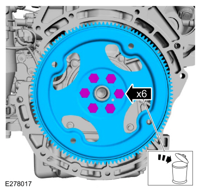
-
-
Remove the bolts and the flexplate.
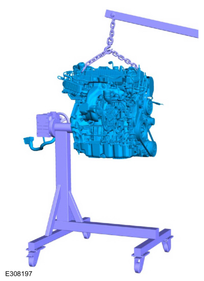
-
Install engine on the mounting stand.
Use the General Equipment: Mounting Stand
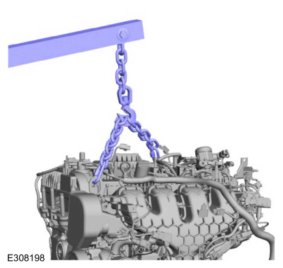
-
Remove the engine lift equipment.
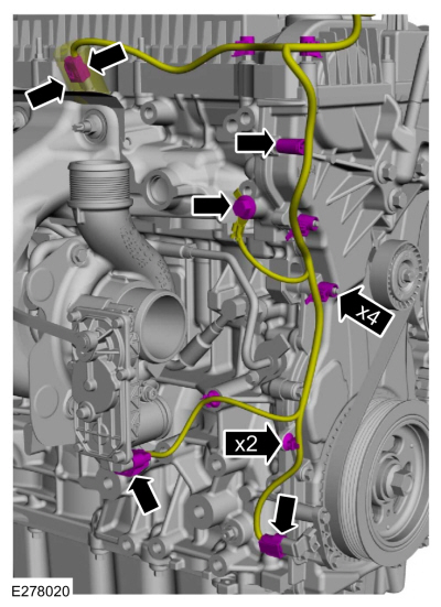
-
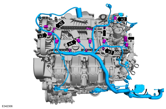
-
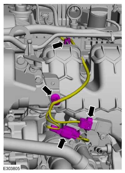
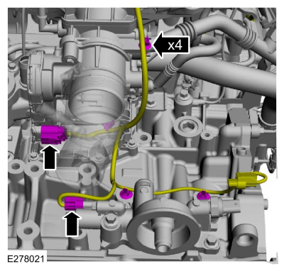
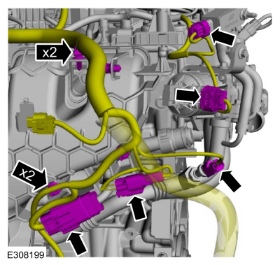
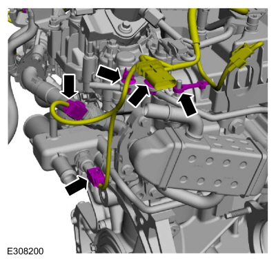
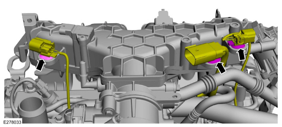
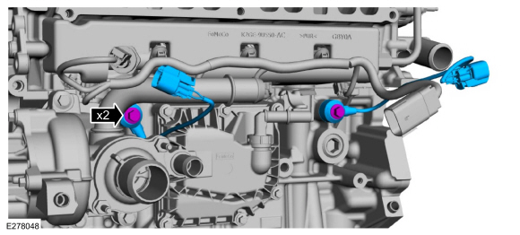
Disconnect the wiring harness electrical connectors.
-
Detach the wiring harness retainers.
-
-
Disconnect the wiring harness electrical connectors.
-
Detach the wiring harness retainers.
-
-
Disconnect the wiring harness electrical connectors.
-
Detach the wiring harness retainers.
-
-
Disconnect the wiring harness electrical connectors.
-
Detach the wiring harness retainers.
-
-
Disconnect the wiring harness electrical connectors.
-
Detach the wiring harness retainers.
-
-
Disconnect the wiring harness electrical connectors.
-
Detach the wiring harness retainers and remove the engine wiring harness.
-
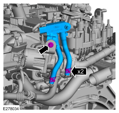
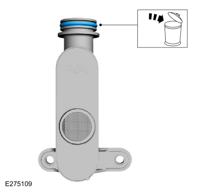
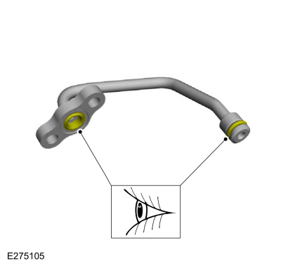
Remove the bolts and the coolant tube.
-
Inspect the coolant tube O-ring seal and replace if damaged.
-
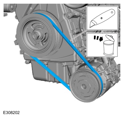
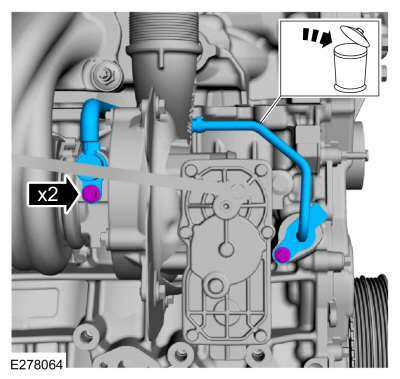
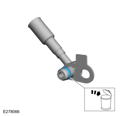
Cut the A/C compressor belt.
Use the General Equipment: Knife
-
-
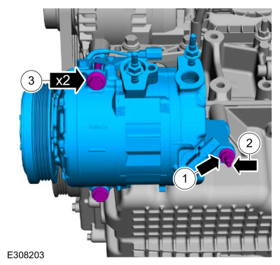
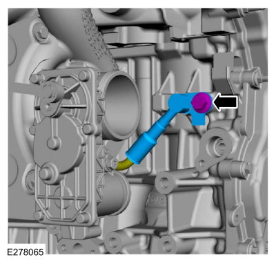
Remove the A/C compressor nut.
-
Remove the A/C compressor stud.
-
Remove the bolts and the A/C compressor.
-
Remove the bolt (Enhanced Hexalobular or TORX PLUS ® Acument
Intellectual Properties, LLC as the owner) and the shield.
-
Loosen the coolant pump pulley bolts.
-
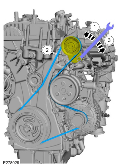
-
Install the tool and release the tension on the accessory drive belt tensioner.
-
Remove the accessory drive belt.
-
Release the tension and remove the tool.
-
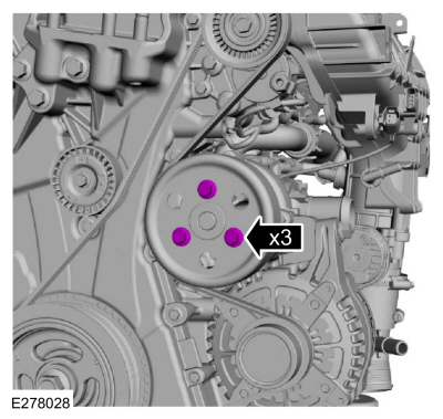
Remove the bolts and the coolant pump pulley.
-
Remove the bolts and the accessory drive belt tensioner.
-
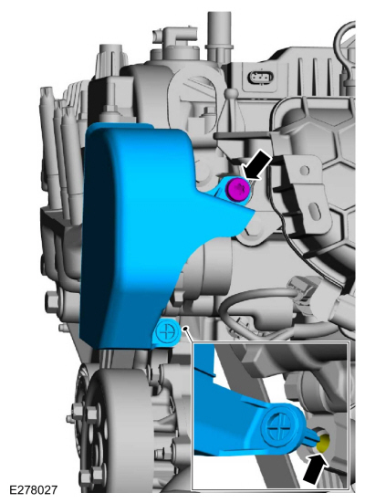
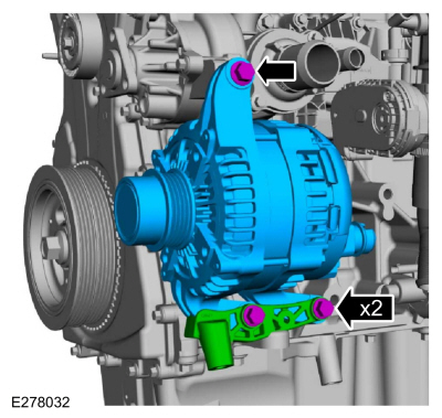
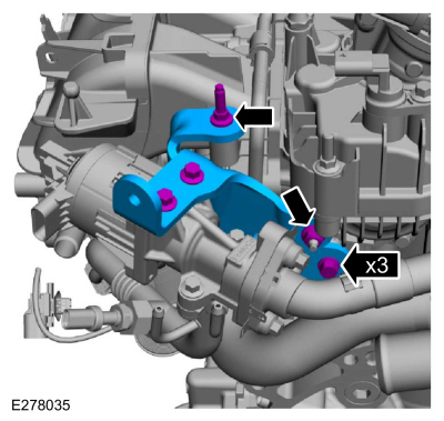
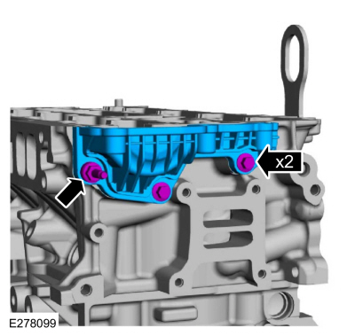
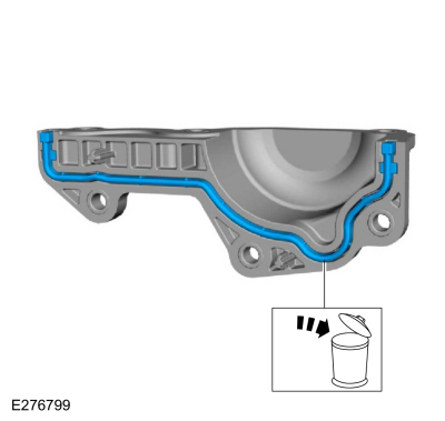
Remove the bolts, oil pan bracket and the generator.
-
Remove the bolt and the ground cable.
-
Detach the wiring connector retainers from the intake manifold.
-
-
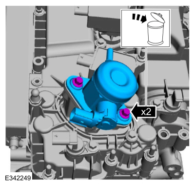
Loosen the clamps and remove the EGR transducer hoses.
-
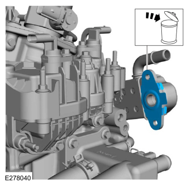
Remove the bolt and the EGR transducer assembly.
-
Remove the stud bolt, nut, bolts and the EGR bracket.
-
Remove the bolts and the EGR valve.
-
Remove and discard EGR valve gaskets.
-
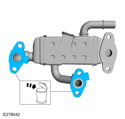
Remove the bolts and the EGR outlet tube assembly.
-
Remove and discard the EGR outlet tube assembly O-ring seal.
-
Remove the bolts, stud bolt and the EGR inlet tube assembly.
-
Remove and discard the EGR inlet tube gasket.
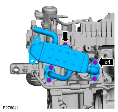
-
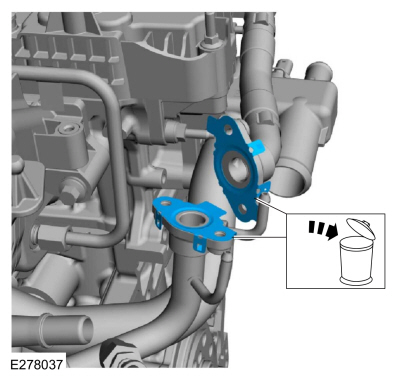
Remove the bolts and the EGR cooler.
-
Remove and discard EGR cooler gaskets.
-
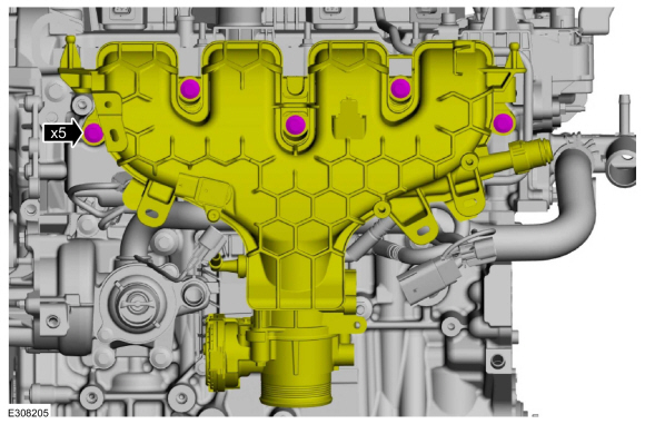
Remove the bolts and position the intake manifold forward.
-
Disconnect the crankcase vent oil separator tube and remove the intake manifold.
Refer to: Quick Release Coupling (310-00B Fuel System - General Information - 2.3L EcoBoost (199kW/270PS), General Procedures).
-
Remove the bolts and the oil filter adapter.
-
Release the clamps and remove the coolant hose.
Use the General Equipment: Hose Clamp Remover/Installer
-
Disconnect the crankcase vent oil separator tube and remove.
Refer to: Quick Release Coupling (310-00B Fuel System - General Information - 2.3L EcoBoost (199kW/270PS), General Procedures).
-
NOTE:
Note the position of the KS before removing.
Remove the bolts and the KS .
-
Remove the bolts and the crankcase vent separator.
-
NOTE:
To release the fuel pressure in the high pressure fuel
tube, wrap the fuel injection pump flare nut with a shop towel to absorb
any residual fuel pressure during the loosening of the fuel injection
pump flare nut.
-
Remove the high-pressure fuel tube bolts.
-
Loosen the flare nuts, remove and discard the high-pressure fuel tube.
-
-
Remove and discard the bolts.
-
Remove the high-pressure fuel pump.
-
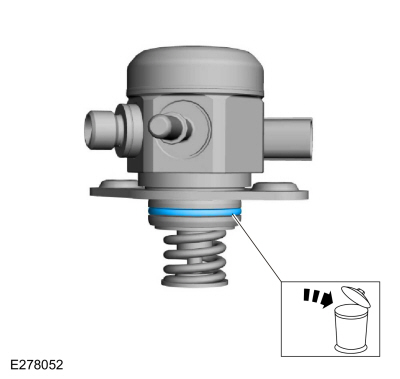
Remove and discard the high-pressure fuel pump O-ring seal.
-
Remove the high-pressure fuel pump tappet.
-
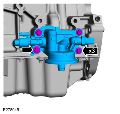
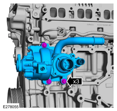
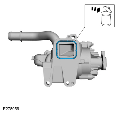
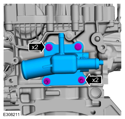
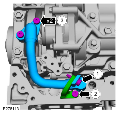
Remove the bolts and the coolant pump adapter assembly.
-
Remove and discard the coolant pump adapter assembly gasket.
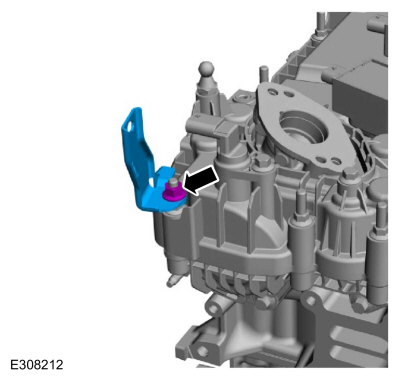
-
Remove the bolt coolant hose bracket.
-
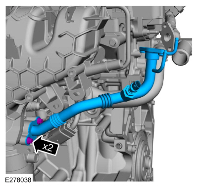
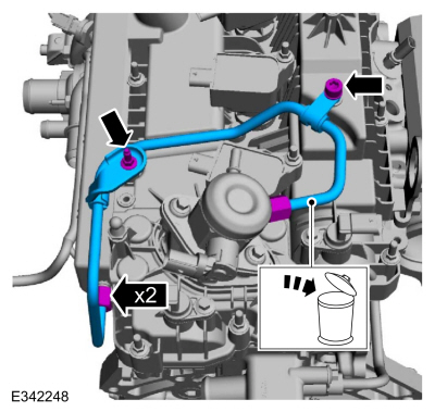
-
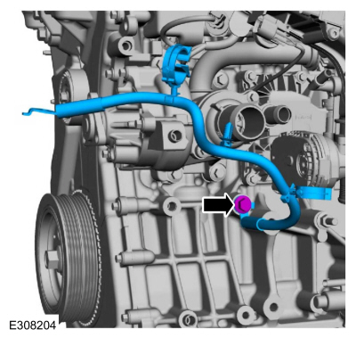
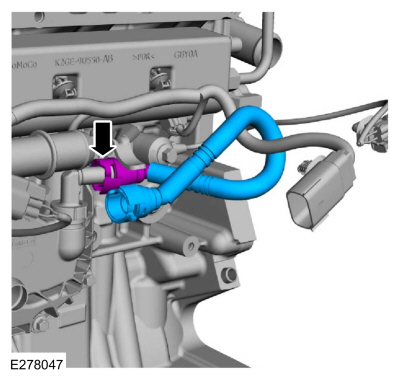
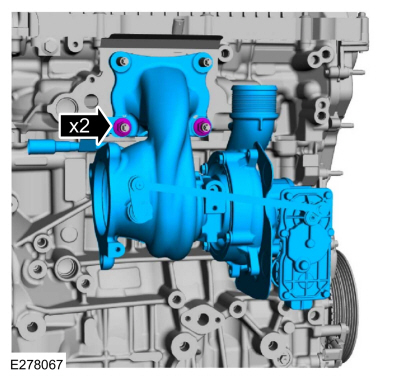
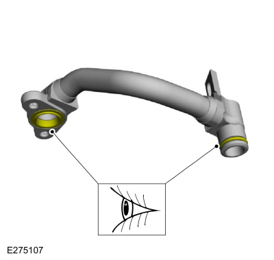
Remove the turbocharger coolant inlet tube nut and bolt.
-
Remove the turbocharger coolant inlet tube.
-
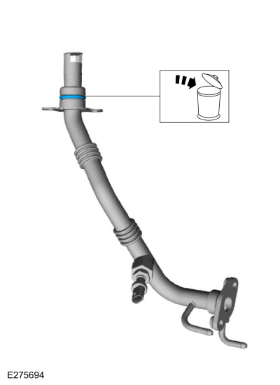
-
Remove and discard the turbocharger coolant inlet tube seal.
-
Inspect the coolant outlet tube seal for damage.
-
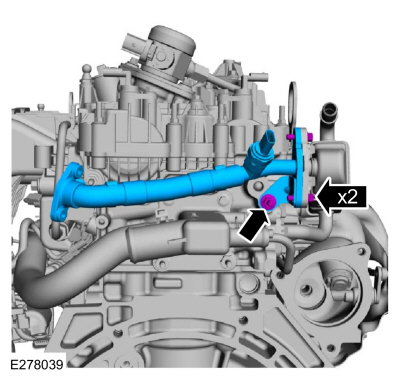
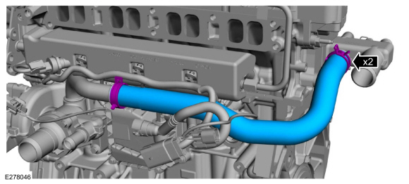
Remove the bolts and discard the turbocharger-to-cylinder block oil return pipe.
-
Remove the nuts, bolt and the heat shield.
-
Remove the bolts and discard the cylinder block-to-turbocharger oil supply pipe.
-
Remove the bolt and the coolant outlet tube.
-
Remove and discard coolant outlet tube O-ring seal.
-
Remove the nut and the turbocharger.
-
Inspect the coolant outlet tube seal for damage.
-
-
Remove and discard the gasket.
-
Inspect and replace the studs if damaged.
-
Remove the nuts and the CAC pipe bracket.
-
Remove the stud bolts, bolts and the coolant outlet.
-
Remove the nut and the fuel tube bracket.
-
NOTE:
When removing the ignition coil-on-plugs, a slight twisting motion will break the seal and ease removal.
-
Use compressed air to remove any foreign material from
the ignition coil-on-plugs and surrounding area before removing the
ignition coil-on-plugs.
-
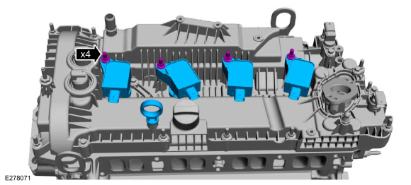
Remove the stud bolts and the ignition coil-on-plugs.
-
Remove the oil level indicator.
-
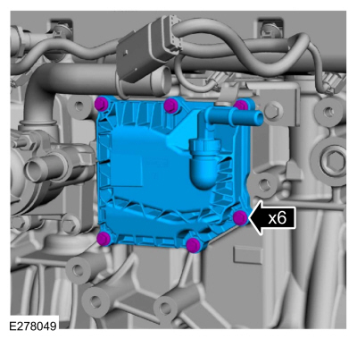
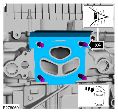
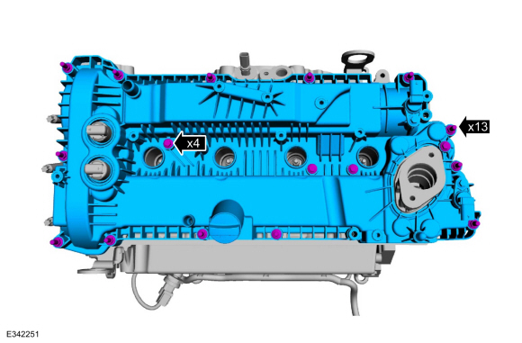
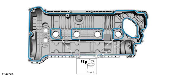
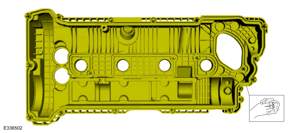
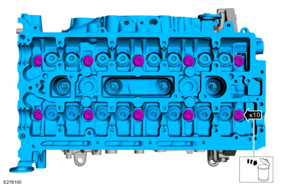
Loosen the fasteners and remove the valve cover.
-
Discard the valve cover gaskets.
-
-
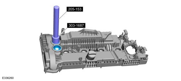
If damaged, using the special tools, remove and discard the VCT oil control solenoid seals.
Use Special Service Tool: 303-1687
Installer, VCT Solenoid Seal.
, 205-153
(T80T-4000-W)
Handle.
-
NOTE:
Do not use metal scrapers, wire brushes, power abrasive
discs or other abrasive means to clean the sealing surfaces. These tools
cause scratches and gouges which make leak paths.
Clean the valve cover.
-
NOTICE:
Do not use metal scrapers, wire brushes, power abrasive
discs or other abrasive means to clean the sealing surfaces. These tools
cause scratches and gouges which make leak paths.
Make sure that the mating faces are clean and free of foreign material.
-
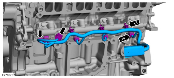
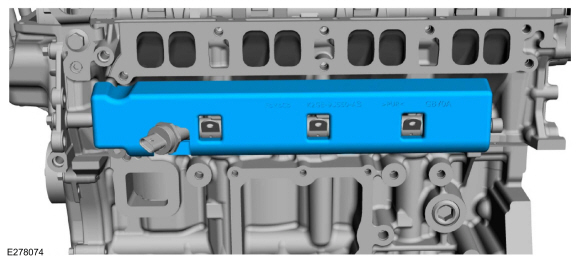
-
Disconnect the fuel rail wiring harness electrical connectors.
-
Detach the fuel rail wiring harness retainers and remove harness.
-
Remove the fuel rail insulator.
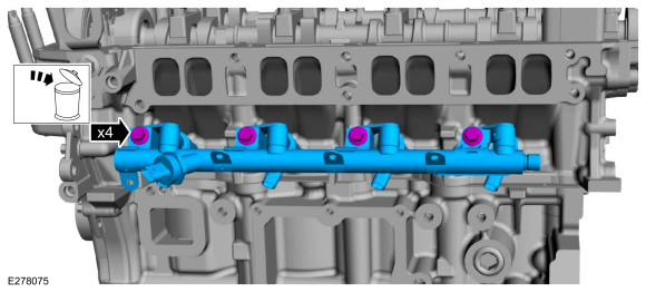
-
NOTICE:
Pull out the fuel rails in the direction of the fuel injector axis or damage may occur to the fuel injectors.
NOTE:
When removing the fuel rails, the fuel injectors may
remain in the fuel rails but normally remain in the cylinder head and
require the use of a Fuel Injector Remover tool to extract.
-
Use compressed air and remove any dirt or foreign
material from the cylinder head, block and general surrounding area of
the fuel rail and injectors.
-
Remove and discard the bolts.
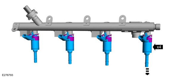
-
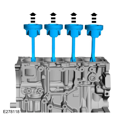
Remove any of the fuel injectors that remained in the fuel rail.
-
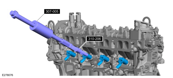
Remove any of the fuel injectors that remained in the cylinder head.
Use Special Service Tool: 307-005
(T59L-100-B)
Slide Hammer.
, 310-206
Remover, Fuel Injector.
-
Remove and discard the fuel injector clips.
-
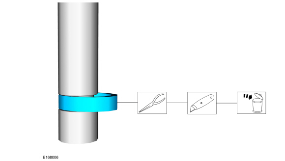
NOTICE:
Use care when removing the lower Teflon® seals, not to scratch, nick or gouge the fuel injectors.
NOTICE:
Do not attempt to cut the lower Teflon® seal without
first pulling it away from the fuel injector or damage to the injector
may occur.
-
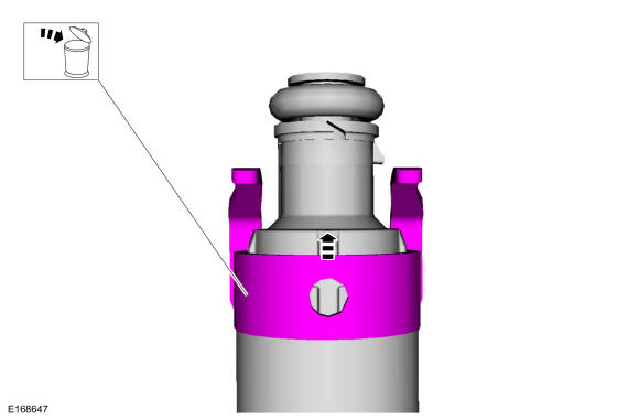
Pull the lower Teflon® seal away from the injector.
-
Carefully cut and discard the lower fuel injector Teflon® seal.
-
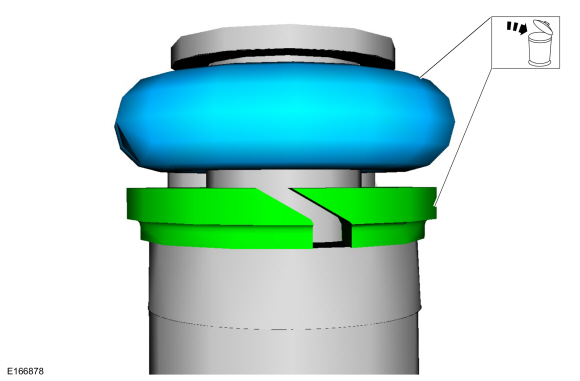
NOTE:
Note the correct orientation of the fuel injector support rings for correct installation.
Remove and discard the fuel injector O-rings. Remove and discard the fuel injector support rings.
-
-
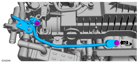
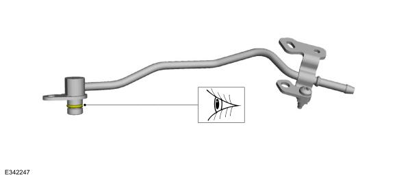
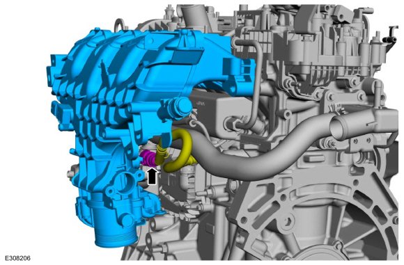
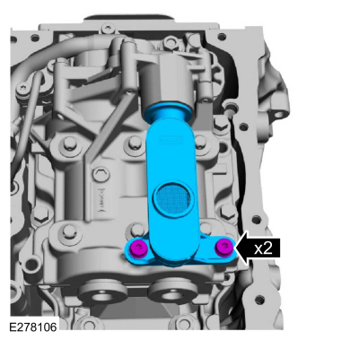
Remove the CHT sensor and the heat shield.
-
Remove the bolts and the CKP sensor.
-
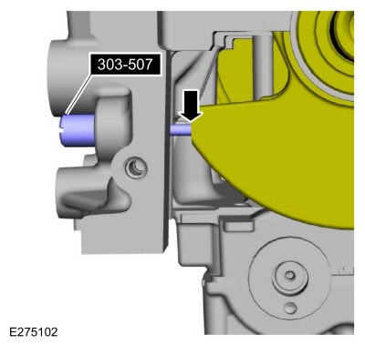
Turn the crankshaft clockwise until the No.1 piston is 45 degrees BTDC
using the guide holes on the engine front cover and the crankshaft
pulley.
-
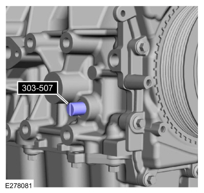
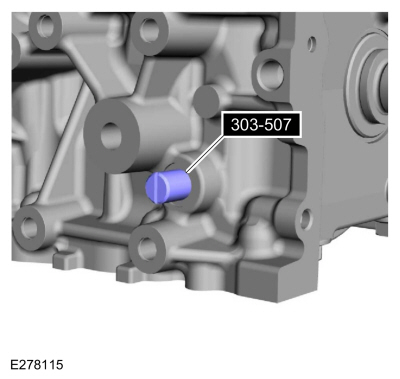
Remove the engine plug bolt.
-
Install Special Service Tool: 303-507
Timing Peg, Crankshaft TDC.
-
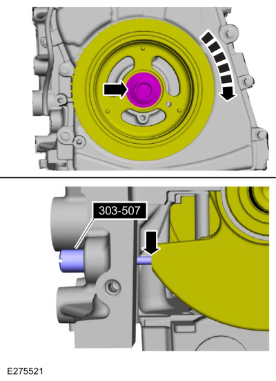
NOTE:
The special tool will contact the crankshaft and prevent it from
turning past TDC . However, the crankshaft can still be rotated in the
counterclockwise direction. The crankshaft must remain at the TDC
position during the crankshaft pulley removal and installation.
NOTE:
The engine front cover is removed from graphic for clarity.
Rotate the crankshaft clockwise until it contacts the special tool.
Use Special Service Tool: 303-507
Timing Peg, Crankshaft TDC.
-
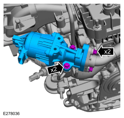
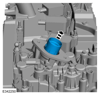
Remove the bolts and the high-pressure fuel pump drive unit.
-
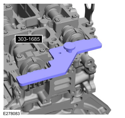
NOTICE:
The Camshaft Alignment Tool is for camshaft alignment
only. Using this tool to prevent engine rotation can result in engine
damage.
NOTE:
The camshaft timing slots are offset. If the Camshaft Alignment Tool cannot be installed, remove the TDC
Timing Peg and rotate the crankshaft three-fourths of a revolution
clockwise and repeat the previous 2 steps of this procedure.
Install Special Service Tool: 303-1685
Alignment Tool, Camshaft.
-
NOTICE:
The crankshaft must remain in the TDC
position during removal of the pulley bolt or damage to the engine can
occur. Therefore, the crankshaft pulley must be held in place with the
special tool and the bolt should be removed using an air impact wrench
(1/2-in drive minimum).
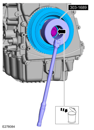
-
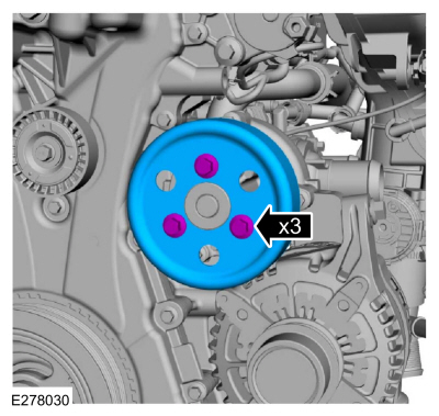
Using the special tools, remove the bolt and the crankshaft pulley.
Use Special Service Tool: 303-1689
Holding Tool, Crank Damper.
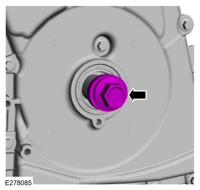
-
Install the original crankshaft pulley bolt and washer.
-
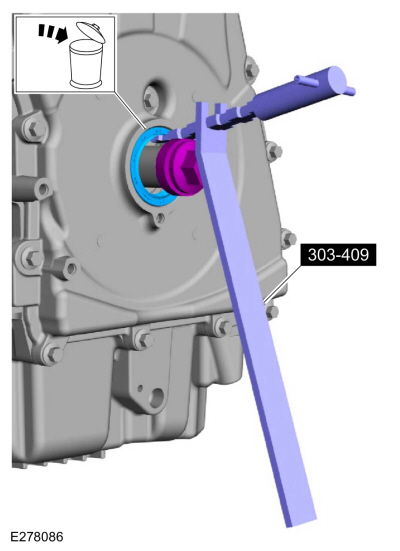
NOTICE:
Use care not to damage the engine front cover or the crankshaft when removing the seal.
Using the crankshaft seal remover, remove the crankshaft front seal and discard.
Use Special Service Tool: 303-409
(T92C-6700-CH)
Remover, Crankshaft Seal.
-
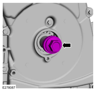
Remove the original crankshaft pulley bolt and washer.
-
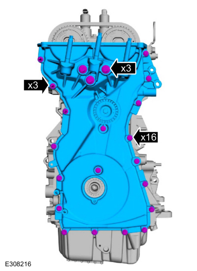
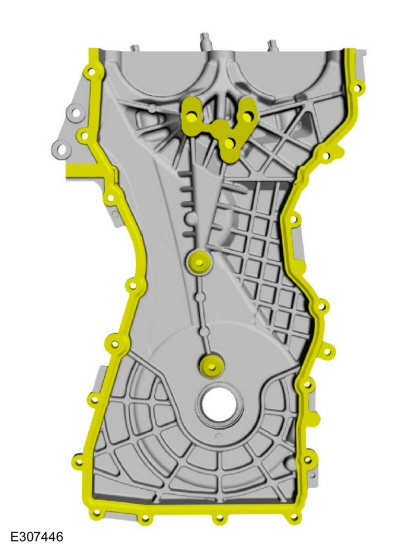
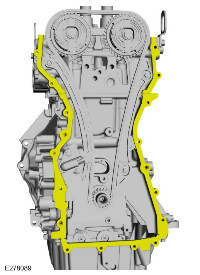
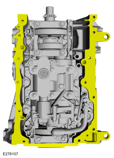
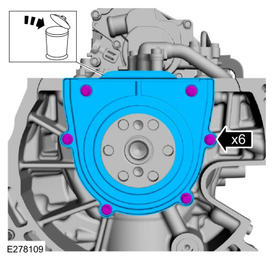
Remove the bolts and the engine front cover.
-
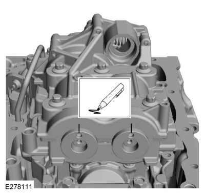
Clean and prepare the RTV sealing surface.
Refer to: RTV Sealing Surface Cleaning and Preparation (303-00 Engine System - General Information, General Procedures).
-
Clean and prepare the RTV sealing surface.
Refer to: RTV Sealing Surface Cleaning and Preparation (303-00 Engine System - General Information, General Procedures).
-
NOTICE:
Use an open-ended wrench on the flats of the camshaft to prevent the component from turning.
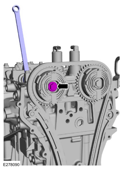
Loosen the exhaust VCT bolt.
-
NOTICE:
Use an open-ended wrench on the flats of the camshaft to prevent the component from turning.
Loosen the intake VCT bolt.
-
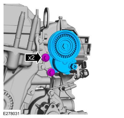
Remove the bolts and the timing chain tensioner.
-
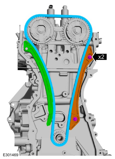
Remove the bolts and the timing chain guide, timing chain and tensioner arm.
-
-
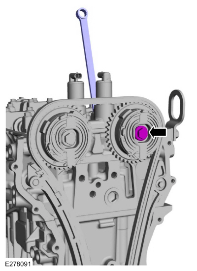
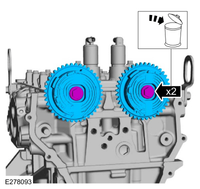
Remove the bolts and the VCT units.
-
Remove Special Service Tool: 303-1685
Alignment Tool, Camshaft.
-
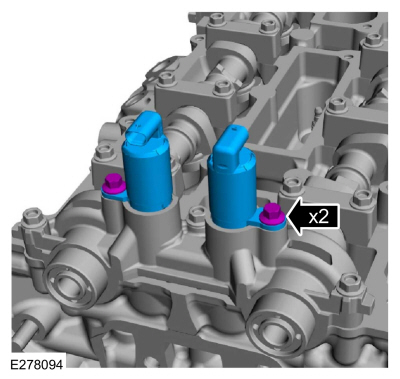
Remove the bolts and the VCT oil control solenoids.
-
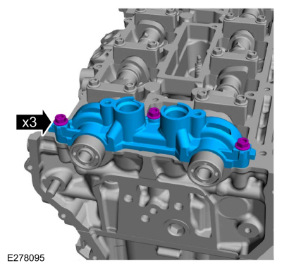
Remove bolts and front camshaft bearing cap.
-
NOTICE:
Failure to follow the camshaft loosening procedure can result in damage to the camshafts.
-
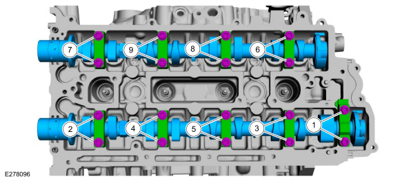
Note the location and orientation of each camshaft
bearing cap and the position of the camshaft lobes on the No. 1 cylinder
for installation reference.
-
Loosen the camshaft bearing caps in sequence 2 turns at a
time until all tension is released from the camshaft bearing caps and
remove the camshaft bearing caps and camshafts.
-
Inspect the camshaft bores for any scratches that can be felt by hand.
-
-
If the camshafts and valve tappets are to be reused,
mark the location of the valve tappets to make sure they are assembled
in their original positions.
-
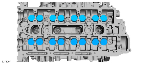
Remove the valve tappets.
-
NOTE:
The number on the valve tappets only reflects the digits
that follow the decimal. For example, a tappet with the number 0.650
has the thickness of 3.650 mm.
Inspect the valve tappets.
-
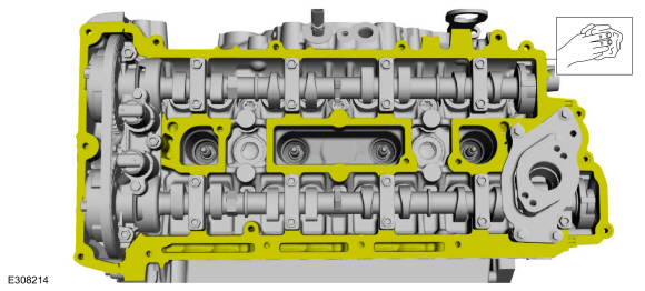
Remove the bolts, stud bolt and the cylinder head cover assembly.
-
Remove and discard the cylinder head cover gasket.
-
-
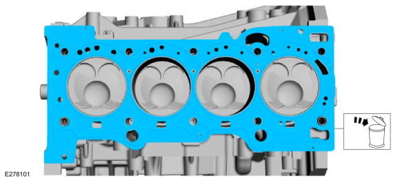
Remove the bolts and the cylinder head.
-
Remove and discard the cylinder head gasket.
-
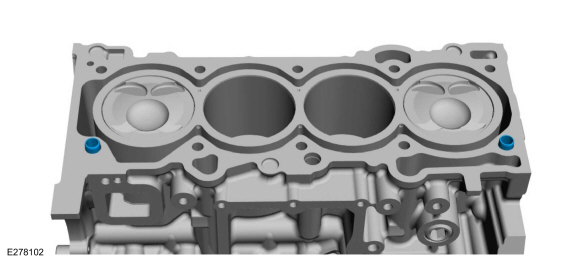
Remove the cylinder block bushings.
-
NOTICE:
Do not use metal scrapers, wire brushes, power abrasive
discs or other abrasive means to clean the sealing surfaces. These tools
cause scratches and gouges that make leak paths. Use a plastic scraping
tool to remove all traces of the head gasket.
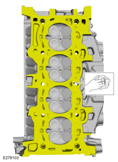
Clean the cylinder head sealing surfaces.
-
NOTICE:
Do not use metal scrapers, wire brushes, power abrasive
discs or other abrasive means to clean the sealing surfaces. These tools
cause scratches and gouges that make leak paths. Use a plastic scraping
tool to remove all traces of the head gasket.
-
Clean the cylinder head bolt holes in the cylinder
block. Make sure all coolant, oil or other foreign material is removed.
-
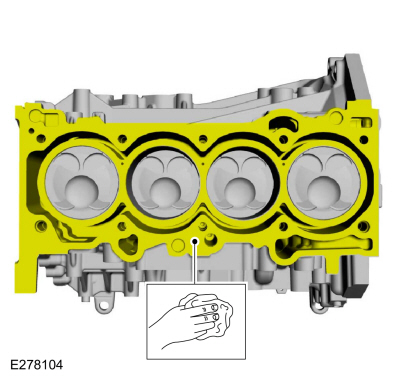
Clean the cylinder block sealing surfaces.
-
-
Check the cylinder block distortion.
Refer to: Cylinder Block Distortion (303-00 Engine System - General Information, General Procedures).
-
Check the cylinder head distortion.
Refer to: Cylinder Head Distortion (303-00 Engine System - General Information, General Procedures).
-
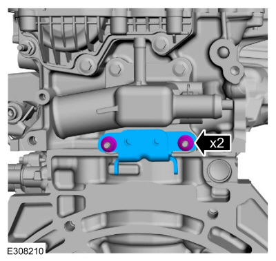
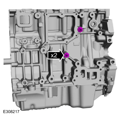
Remove the wiring harness retainer stud bolts.
-
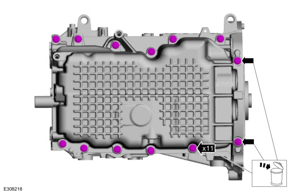
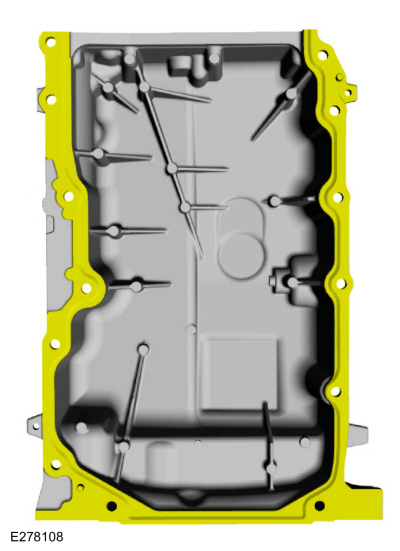
Remove and discard the oil pan bolts.
-
NOTICE:
Do not strike the oil pan sideways to remove, the oil pan is doweled and will damage the oil pan and block.
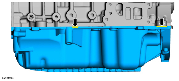
Using the pry pads, remove the oil pan.
-
Clean and prepare the RTV sealing surface.
Refer to: RTV Sealing Surface Cleaning and Preparation (303-00 Engine System - General Information, General Procedures).
-
Clean and prepare the RTV sealing surface.
Refer to: RTV Sealing Surface Cleaning and Preparation (303-00 Engine System - General Information, General Procedures).
-
Remove the bolts and the oil pickup and screen.
-
Discard the oil pickup and screen O-ring seal.
-
-
Remove the bolts and the crankshaft rear seal.
-
Discard the crankshaft rear seal.
-
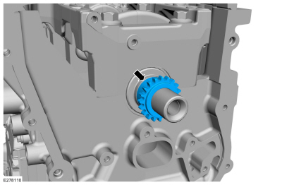
Remove the crankshaft sprocket.
-
NOTE:
Make sure the Crankshaft TDC Timing Peg is still installed and the engine is still at TDC .
Rotate the crankshaft until it contacts the special tool.
-
NOTE:
Mark the balance shaft assembly front shafts on the top for reference that the balance shaft assembly is at TDC .
Index-mark the balance shaft assembly.
-
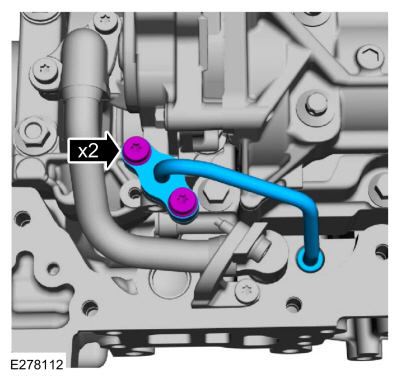
Remove the bolts and the oil outlet tube.
-
Inspect the oil outlet tube O-ring seals and replace if damaged.
-
-
Remove the oil inlet tube-to-bracket bolt.
-
Remove the bolt and the oil inlet tube bracket.
-
Remove the bolts and the oil inlet tube.
-
Inspect the oil inlet tube O-ring seals and replace if damaged.
-
NOTE:
Due to the precision interior construction of the balance shaft assembly, it should not be disassembled.
Remove the bolts and the balance shaft assembly.
-
Remove Special Service Tool: 303-507
Timing Peg, Crankshaft TDC.
-
-
Inspect ridge.
-
NOTE:
Remove the carbon buildup, do not scratch the cylinder wall. Remove all debris from the cylinder.
Clean with abrasive pad.
-
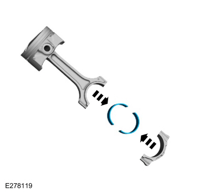
NOTE:
Clearly mark the connecting rods, connecting rod caps
and connecting rod bearings in numerical order for correct orientation
for reassembly.
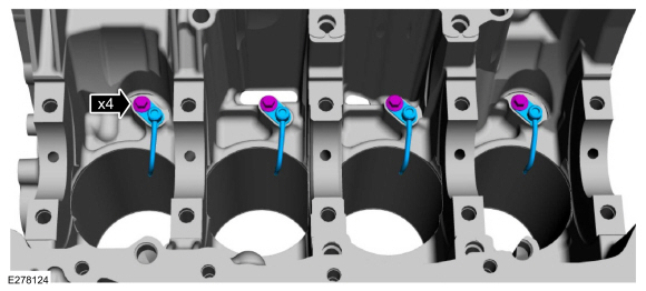
Remove the bolts and the connecting rod caps.
-
NOTICE:
Do not scratch the cylinder walls or crankshaft journals with the connecting rod.
Remove the pistons.
-
NOTE:
Mark the position of the parts, so they can be installed in their original positions.
Remove the connecting rod bearings.
Refer to: Piston Inspection (303-00 Engine System - General Information, General Procedures).
-
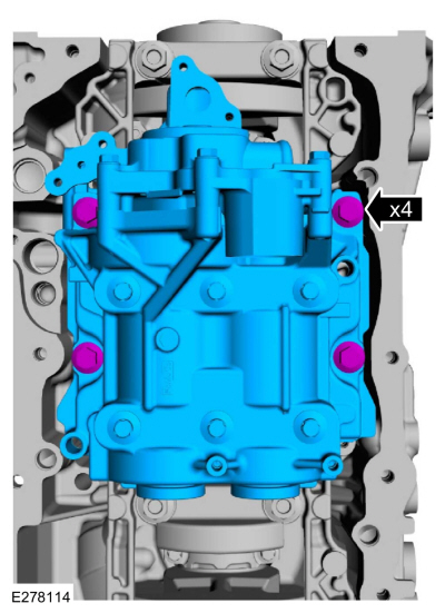
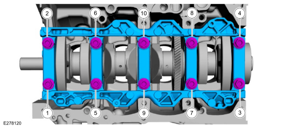
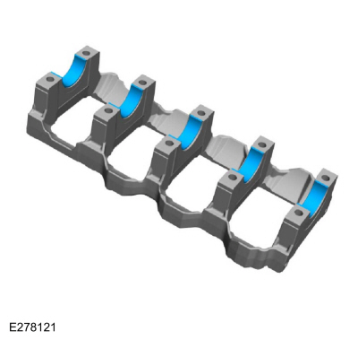
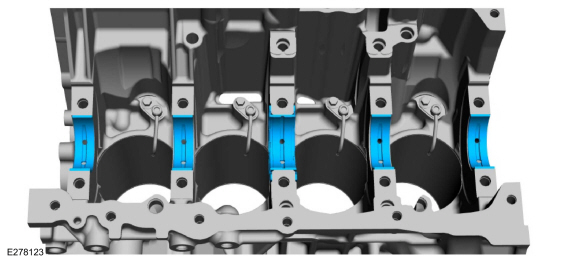
Remove the bolts and the main bearing beam.
-
NOTE:
If the main bearings are being reused, mark them in order for correct orientation and reassembly.
Remove the main bearing beam bearings.
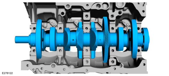
-
Remove the crankshaft.
-
NOTE:
If the main bearings are being reused, mark them in order for correct orientation and reassembly.
NOTE:
The center bulkhead has the thrust bearing.
Remove the crankshaft main bearings.
-
Remove the bolts and the engine piston oil cooler valves.
-
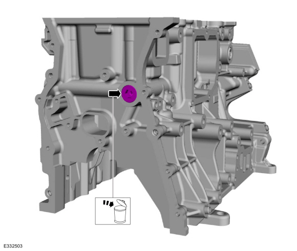
If necessary, remove and discard the front cylinder block plug.
-
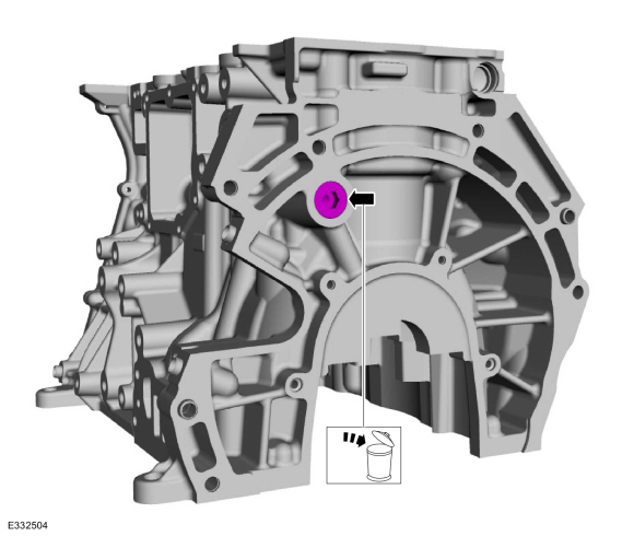
If necessary, remove and discard the rear cylinder block plug.
Special Tool(s) /
General Equipment
303-1249Valve Spring CompressorTKIT-2006UF-FLMTKIT-2006UF-ROW
303-1567Sizer, Teflon SealTKIT-2010C-FLM
303-300
(T87C-6565-A)
Set, Valve Spring CompressorTKIT-1988-FESTIVAT88C-1000-STTKIT-1988-TRACERTKIT-2009TC-F
303-350
(T89P-6565-A)
Compressor, Valve SpringTKIT-1990-LMHTKIT-1989-FTKIT-1989-FMTKIT-1989-FLM
303-472
(T94P-65..
Other information:
Removal
WARNING:
The Tire Pressure Monitoring System (TPMS) sensor
battery may release hazardous chemicals if exposed to extreme mechanical
damage. If these chemicals contact the skin or eyes, flush immediately
with water for a minimum of 15 minutes and get prompt medical attention.
If any part of the battery is swallowed, contact a physician
immediately. When disposing of Ti..
Removal
NOTE:
Removal steps in this procedure may contain installation details.
NOTE:
LH side shown, RH side similar.
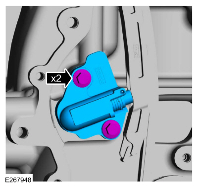
Remove the wheel and tire.
Refer to: Wheel and Tire (204-04A Wheels and Tires, Removal and Installation).
Remove the bolts.
Torque:
13 lb.in (1.5 Nm)
Remove the bolts.
Torque:
22 lb.in (2.5 Nm)
..
 Removal - Engine
 Disassembly and Assembly of Subassemblies - Cylinder Head
 Select the settings option on
the
feature bar.
Select the settings option on
the
feature bar.