Lincoln Corsair: Engine - 2.0L EcoBoost (177kW/240PS) – MI4 / Disassembly and Assembly of Subassemblies - Cylinder Head
Special Tool(s) / General Equipment
 |
303-1249 Valve Spring Compressor TKIT-2006UF-FLM TKIT-2006UF-ROW |
 |
303-1567 Sizer, Teflon Seal TKIT-2010C-FLM |
 |
303-300
(T87C-6565-A)
Set, Valve Spring Compressor TKIT-1988-FESTIVA T88C-1000-ST TKIT-1988-TRACER TKIT-2009TC-F |
 |
303-350
(T89P-6565-A)
Compressor, Valve Spring TKIT-1990-LMH TKIT-1989-F TKIT-1989-FM TKIT-1989-FLM |
 |
303-472
(T94P-6565-AH)
Adapter, Valve Spring Compressor TKIT-1994-LMH/MH2 TKIT-1994-FH/FMH/FLMH |
 |
307-005
(T59L-100-B)
Slide Hammer |
 |
310-205 Fuel Injector Brush |
 |
310-206 Remover, Fuel Injector TKIT-2009A-FLM |
 |
310-207 Installer, Fuel Injector Seal Assembly TKIT-2009A-FLM |
| Knife | |
| Long Nose Pliers | |
Materials
| Name | Specification |
|---|---|
| Motorcraft® Multi-Purpose Grease Spray XL-5-A |
ESB-M1C93-B |
DISASSEMBLY
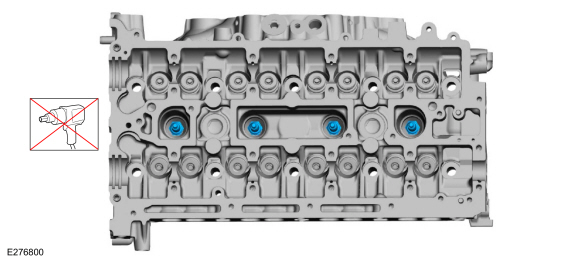
NOTICE: During engine repair procedures, cleanliness is extremely important. Any foreign material, including any material created while cleaning gasket surfaces, that enters the oil passages, coolant passages or the oil pan can cause engine failure.
NOTICE: Aluminum surfaces are soft and can be scratched easily. Never place the cylinder head gasket surface, unprotected, on a bench surface.
NOTE: If the components are to be reinstalled, mark the location of the components removed, they must be installed in the same location.
-
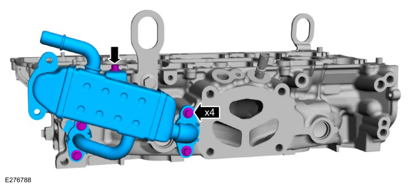
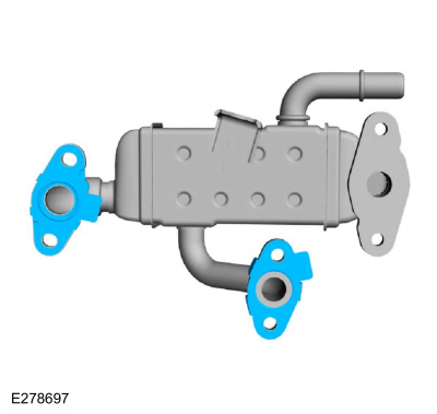
Remove the bolts and the EGR cooler.
 |
-
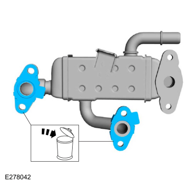
Remove and discard the EGR cooler gaskets.
 |
-
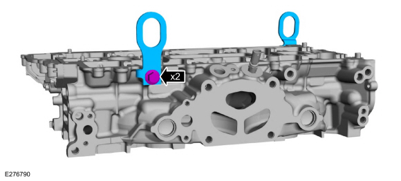
If equipped, remove the bolts and the engine lift eyes.
 |
-
-
Remove the CHT sensor and the exhaust manifold heat shield.
-
Discard the CHT sensor.
-
Remove the CHT sensor and the exhaust manifold heat shield.
 |
-
NOTICE: Pull out the fuel rails in the direction of the fuel injector axis or damage may occur to the fuel injectors.
NOTE: When removing the fuel rails, the fuel injectors may remain in the fuel rails but normally remain in the cylinder head and require the use of a Fuel Injector Remover tool to extract.
-
Use compressed air and remove any dirt or foreign
material from the cylinder head, block and general surrounding area of
the fuel rail and injectors.
-
Remove the bolts and the fuel rail.
-
Use compressed air and remove any dirt or foreign
material from the cylinder head, block and general surrounding area of
the fuel rail and injectors.
 |
-
Remove any of the fuel injectors that remained in the fuel rail.
 |
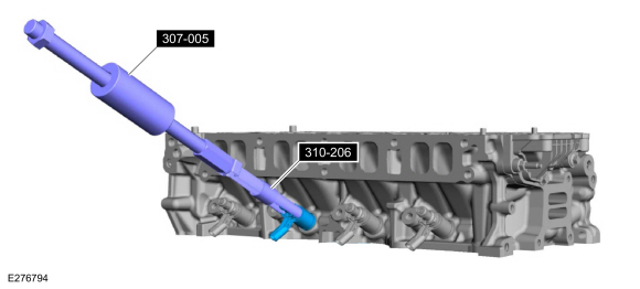
-
Remove any of the fuel injectors that remained in the cylinder head.
Use Special Service Tool: 310-206 Remover, Fuel Injector. , 307-005 (T59L-100-B) Slide Hammer.
 |
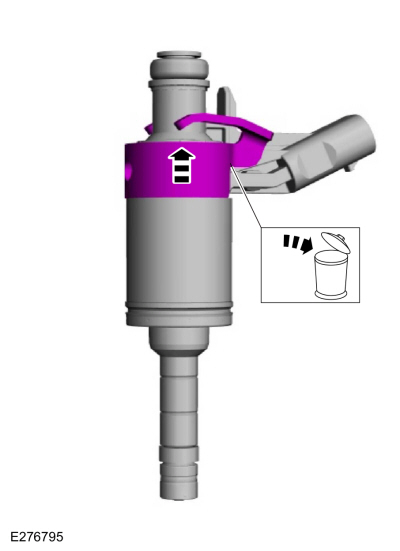
-
Remove the fuel injector clip.
 |
-
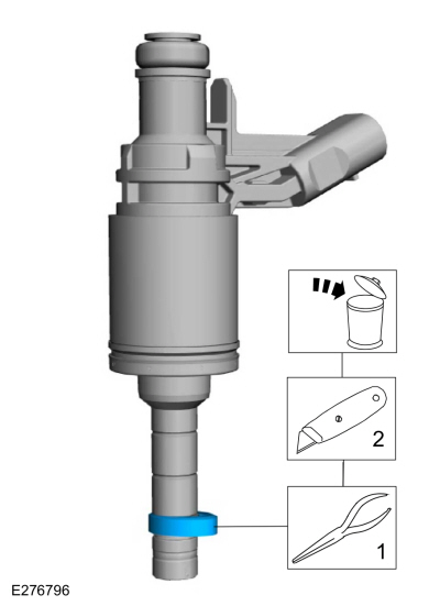
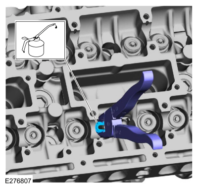
NOTICE: Do not attempt to cut the lower Teflon® seal without first pulling it away from the fuel injector or damage to the injector may occur.
NOTE: Be very careful when removing the lower Teflon® seals, not to scratch, nick or gouge the fuel injectors.
-
Pull the lower Teflon® seal away from the injector.
Use the General Equipment: Long Nose Pliers
-
Carefully cut and discard the lower fuel injector Teflon® seals.
Use the General Equipment: Knife
-
Pull the lower Teflon® seal away from the injector.
 |
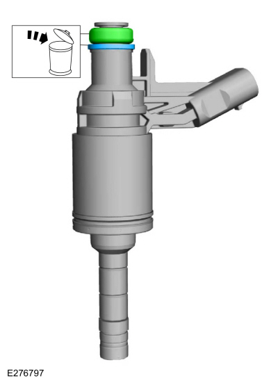
-
Remove and discard the O-ring seal and fuel injector seal.
 |
-
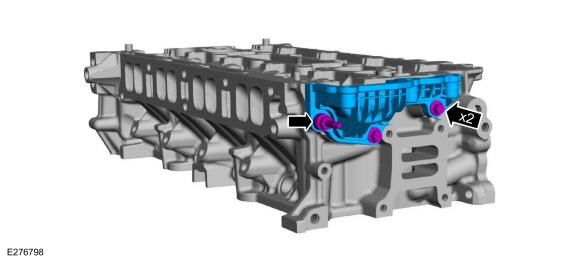
Remove the bolts, stud bolt and the cylinder head cover.
 |
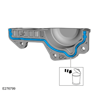
-
Remove and discard the cylinder head cover gasket.
 |
-
-
Use compressed air to remove any foreign material in the spark plug well before removing the spark plugs.
-
Remove the spark plugs.
-
Use compressed air to remove any foreign material in the spark plug well before removing the spark plugs.
 |
-
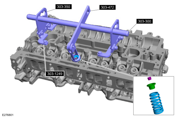
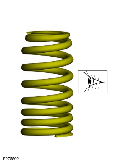
NOTICE: The intake and exhaust valve springs appear similar but are different parts and are not interchangeable. If the springs are to be reused they must be installed in their original location.
NOTE: Use a small screwdriver and multi-purpose grease to remove the valve collets.
Using the special tools, remove the valve collet, valve spring retainer and the valve spring.
Use Special Service Tool: 303-300 (T87C-6565-A) Set, Valve Spring Compressor. , 303-350 (T89P-6565-A) Compressor, Valve Spring. , 303-472 (T94P-6565-AH) Adapter, Valve Spring Compressor. , 303-1249 Valve Spring Compressor.
Material: Motorcraft® Multi-Purpose Grease Spray / XL-5-A (ESB-M1C93-B)
 |
-
Inspect and install new parts, as necessary.
 |
-
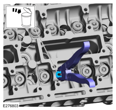
NOTE: Use valve stem seal pliers (such as BeTooll HW0107 or equivalent).
-
Using the special tool, remove the valve seals.
-
Discard the valve stem seal.
-
Using the special tool, remove the valve seals.
 |
-
-
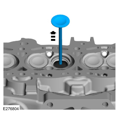
Mark each valve location if the original valves are to be used.
-
Remove the valve.
-
Mark each valve location if the original valves are to be used.
 |
-
Inspect the valve seats.
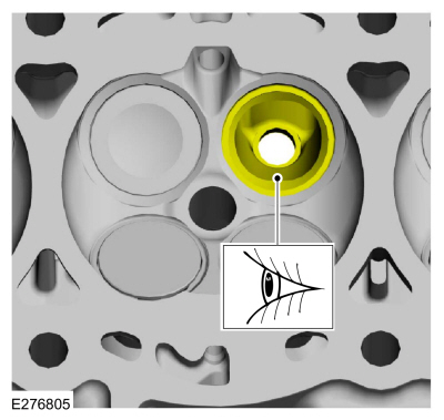 |
-
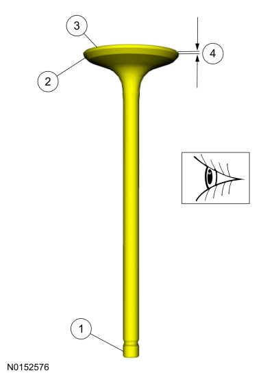
NOTE: Install new parts, as necessary.
-
Inspect the end of the stem for grooves or scoring.
-
Inspect the valve face and the edge for pits, grooves or scores.
-
Inspect the valve head for signs of burning, erosion, warpage and cracking.
-
Inspect the valve margin for wear.
-
Inspect the end of the stem for grooves or scoring.
 |
-
Repeat the appropriate removal steps for all of the other valves.
ASSEMBLY
-
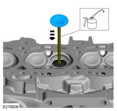
NOTE: If installing the original valves, make sure the valves are installed in the same position from which they were removed.
Lubricate with clean engine oil and install the valve.
 |
-
NOTE: Use valve stem seal pliers (such as BeTooll HW0107 or equivalent).
-
Lubricate the valve stem seal with clean engine oil.
-
Use commercially available valve stem seal pliers to install the valve stem seal.
-
Lubricate the valve stem seal with clean engine oil.
 |
-
NOTICE: The intake and exhaust valve springs appear similar but are different parts and are not interchangeable. If the springs are to be reused they must be installed in their original location.
NOTE: Use a small screwdriver and multi-purpose grease to install the valve collets. Check the seating of the valve collet.
Using the special tools, install the valve spring, valve spring retainer and the valve collet.
Use Special Service Tool: 303-300 (T87C-6565-A) Set, Valve Spring Compressor. , 303-350 (T89P-6565-A) Compressor, Valve Spring. , 303-472 (T94P-6565-AH) Adapter, Valve Spring Compressor. , 303-1249 Valve Spring Compressor.
Material: Motorcraft® Multi-Purpose Grease Spray / XL-5-A (ESB-M1C93-B)
|
-
NOTICE: If a spark plug is dropped, internal damage may result and the spark plug must be discarded. The use of a damaged spark plug may cause cylinder misfire resulting in engine damage.
Install the spark plugs.
Torque: 106 lb.in (12 Nm)
|
-
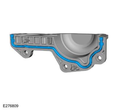
Install a new cylinder head cover gasket.
 |
-
Install the cylinder head cover, bolts and stud bolt.
Torque: 97 lb.in (11 Nm)
|
-
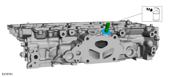
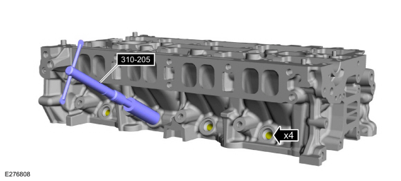
NOTICE: Do not use compressed air or the Fuel Injector Brush to clean the tip of the fuel injectors. Failure to follow this instruction may result in damage to the fuel injectors.
NOTE: Make sure to thoroughly clean any residual fuel or foreign material from the cylinder head, block and the general surrounding area of the fuel rails and injectors.
Using the special tool, clean the fuel injector bores.
Use Special Service Tool: 310-205 Fuel Injector Brush.
 |
-
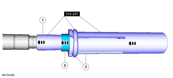
NOTICE: Do not lubricate the new lower Teflon® fuel injector seals.
-
Install the Teflon® Seal Guide onto the fuel injector tip.
Install Special Service Tool: 310-207 Installer, Fuel Injector Seal Assembly.
-
NOTICE: Once the Teflon® seal is installed on the Teflon® Seal Guide, it should immediately be installed onto the fuel injector to avoid excessive expansion of the Teflon® seal.
NOTE: Make sure that new lower fuel injector Teflon® seals are installed.
Install the new Teflon® seals onto the Teflon® Seal Guide, using the Pusher Tool, slide the Teflon® seals along the Teflon® Seal Guide
-
Using the Pusher Tool, slide the Teflon® seals off
of the Teflon® Seal Guide and into the groove on the fuel injectors.
-
Remove the special tool.
Use Special Service Tool: 310-207 Installer, Fuel Injector Seal Assembly.
-
Install the Teflon® Seal Guide onto the fuel injector tip.
 |
-
NOTE: Make sure the Teflon® seal is fully seated in the groove on the fuel injector before sizing the Teflon® seal.
-
Massage and warm the Teflon® seal with your fingers
before the Teflon® seal sizer tool is installed. This will aid in
installing the Teflon® seal sizer tool.
-
NOTE: The beveled opening of the Teflon® seal sizer tool goes away from the seal.
Position the Teflon® seal sizer tool with the larger opening towards the Teflon® seal. Push while turning the Teflon® seal sizer tool 180 degrees.
Use Special Service Tool: 303-1567 Sizer, Teflon Seal.
-
Once the Teflon® seal sizer tool is installed, check
and make sure the Teflon® seal is in the sizing portion of the Teflon®
seal sizer tool. After one minute, turn the Teflon® seal sizer tool back
180 degrees and remove.
-
After one minute, turn the Teflon® seal sizer tool back 180 degrees and remove.
-
Massage and warm the Teflon® seal with your fingers
before the Teflon® seal sizer tool is installed. This will aid in
installing the Teflon® seal sizer tool.
 |
-
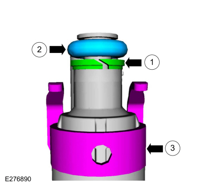
NOTICE: The new the fuel injector support rings must be installed in the correct orientation with the wide surface area facing up against the fuel injector O-ring seals. Improperly installed support rings may cause the fuel system to leak.
NOTE: Make sure that new fuel injector support rings and new fuel injector O-ring seals are installed.
-
Install the new the fuel injector support rings.
-
NOTE: Do not lubricate the new lower Teflon® fuel injector seals.
Install the new fuel injector O-rings.
-
Install the new the fuel injector clips.
-
Install the new the fuel injector support rings.
 |
-
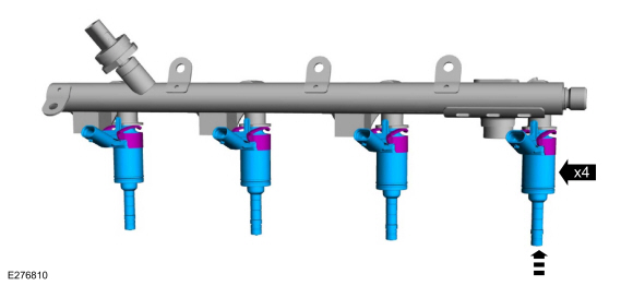
NOTICE: The FRP sensor must be replaced if it is removed from the fuel rail.
NOTE: The anti-rotation finger of the fuel injector clip must slip into the groove of the fuel rail cup.
Install the fuel injectors in the fuel rail.
 |
-
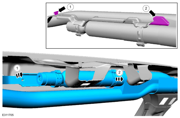
NOTE: Do not lubricate the new lower Teflon® fuel injector seals.
NOTE: No sudden impact force is allowed.
Install the fuel rail by pushing down on the fuel rail above the injectors and install the bolts.
Torque:
Stage 1: Tighten to: 89 lb.in (10 Nm)
Stage 2: Back off to: 0 lb.in (0 Nm)
Stage 3: Wait 5 seconds: 0 turn(s)
Stage 4: Tighten to: 124 lb.in (14 Nm)
Stage 5: Tighten an additional: 30°
 |
-
-
Install the exhaust manifold heat shield on the new CHT sensor.
-
Install the CHT sensor.
Torque: 97 lb.in (11 Nm)
-
Install the exhaust manifold heat shield on the new CHT sensor.
|
-
If equipped, install the engine lift eyes and the bolts.
Torque:
Stage 1: 33 lb.ft (45 Nm)
Stage 2: 30°
|
-
Install the new EGR cooler gaskets.
 |
-
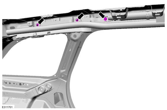
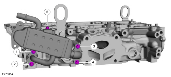
Install the EGR cooler and the bolts finger tight.
|
-
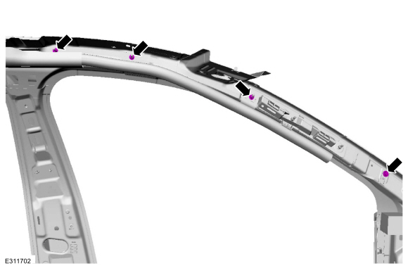
-
Tighten bolts 1 and 2.
Torque: 97 lb.in (11 Nm)
-
Retighten bolt 1.
Torque: 97 lb.in (11 Nm)
-
Tighten bolts 3 and 4.
Torque: 97 lb.in (11 Nm)
-
Retighten bolt 3.
Torque: 97 lb.in (11 Nm)
-
Tighten bolt 5.
Torque: 97 lb.in (11 Nm)
-
Tighten bolts 1 and 2.
 |

 Disassembly and Assembly of Subassemblies - Piston
DISASSEMBLY
NOTE:
If the piston and connecting rod are to be reinstalled, they
must be assembled in the same orientation. Mark the piston orientation
to the connecting rod reassembly...
Other information:
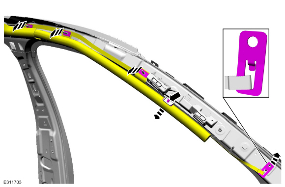
Lincoln Corsair 2020-2026 Service Manual: Removal and Installation - Inner Quarter Panel
Special Tool(s) / General Equipment Resistance Spotwelding Equipment Scraper for Straight Edges Hot Air Gun 8 mm Drill Bit MIG/MAG Welding Equipment Spot Weld Drill Bit Locking Pliers Materials Name Specification Flexible Foam Repair3M™ 08463, LORD Fusor® 121 - Removal WARNING: Electric vehicles damaged by a crash may ha..
Lincoln Corsair 2020-2026 Service Manual: Description and Operation - Gasoline and Gasoline-Ethanol Fuel Systems Health and Safety Precautions
WARNING: Before working on or disconnecting any of the fuel tubes or fuel system components, relieve the fuel system pressure to prevent accidental spraying of fuel. Fuel in the fuel system remains under high pressure, even when the engine is not running. Failure to follow this instruction may result in serious personal injury. WARNING: Do not smoke, carry lighted toba..
Categories
- Manuals Home
- 1st Generation Lincoln Corsair Owners Manual
- 1st Generation Lincoln Corsair Service Manual
- Technical Specifications
- Child Safety Locks
- Selecting a Drive Mode. DRIVE MODES
- New on site
- Most important about car
Audio Unit
WARNING: Driving while distracted can result in loss of vehicle control, crash and injury. We strongly recommend that you use extreme caution when using any device that may take your focus off the road. Your primary responsibility is the safe operation of your vehicle. We recommend against the use of any hand-held device while driving and encourage the use of voice-operated systems when possible. Make sure you are aware of all applicable local laws that may affect the use of electronic devices while driving.