Lincoln Corsair: Engine - 2.0L EcoBoost (177kW/240PS) – MI4 / Removal - Engine
Special Tool(s) /
General Equipment
 |
307-566
Retainer, Torque Converter
TKIT-2006C-FFMFLM
TKIT-2006C-LM
TKIT-2006C-ROW |
| Magnetic Socket |
| Floor Crane |
| Adjustable Mounting Arm |
| Oil Drain Equipment |
| Side Cutter Pliers |
| Hose Clamp Remover/Installer |
| Powertrain Jack |
| Wooden Block |
NOTICE:
The turbocharger compressor vanes can be damaged by even the
smallest particles. When removing any turbocharger or engine air intake
system component, ensure that no debris enters the system. Failure to do
so may result in damage to the turbocharger.
LHD AWD/LHD FWD
-
With the vehicle in NEUTRAL, position it on a hoist.
Refer to: Jacking and Lifting - Overview (100-02 Jacking and Lifting, Description and Operation).
-
Release the fuel system pressure.
Refer to: Fuel System Pressure Release (310-00A Fuel System - General
Information - 2.0L EcoBoost (177kW/240PS) – MI4, General Procedures).
-
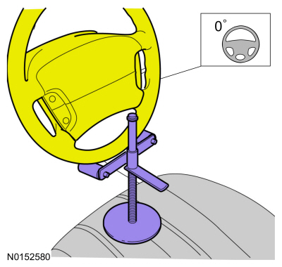
Using a holding device, hold the steering wheel in the straight-ahead position.
-
-
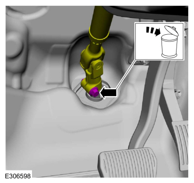
Remove the bolt and discard.
-
Position steering column shaft aside.
-
Evacuate the A/C system.
Refer to: Air Conditioning (A/C) System Recovery,
Evacuation and Charging - Vehicles With: R1234YF Refrigerant (412-00
Climate Control System - General Information)
.
Refer to: Air Conditioning (A/C) System Recovery,
Evacuation and Charging - Vehicles With: R134A Refrigerant (412-00
Climate Control System - General Information)
.
-
Drain the cooling system.
Refer to: Engine Cooling System Draining, Vacuum Filling and Bleeding
(303-03A Engine Cooling - 2.0L EcoBoost (177kW/240PS) – MI4, General
Procedures).
-
Remove the following items:
-
Remove the degas bottle.
Refer to: Degas Bottle (303-03A Engine Cooling - 2.0L EcoBoost (177kW/240PS) – MI4, Removal and Installation).
-
Remove the air cleaner outlet pipe.
Refer to: Air Cleaner Outlet Pipe (303-12A Intake Air Distribution and
Filtering - 2.0L EcoBoost (177kW/240PS) – MI4, Removal and
Installation).
-
Remove the air cleaner.
Refer to: Air Cleaner (303-12A Intake Air Distribution and Filtering -
2.0L EcoBoost (177kW/240PS) – MI4, Removal and Installation).
-
Remove the battery tray.
Refer to: Battery Tray - 2.0L EcoBoost (177kW/240PS) – MI4/2.3L
EcoBoost (199kW/270PS) (414-01 Battery, Mounting and Cables, Removal and
Installation).
-
Remove the EVAP canister purge valve.
Refer to: Evaporative Emission Canister Purge Valve (303-13A
Evaporative Emissions - 2.0L EcoBoost (177kW/240PS) – MI4, Removal and
Installation).
-
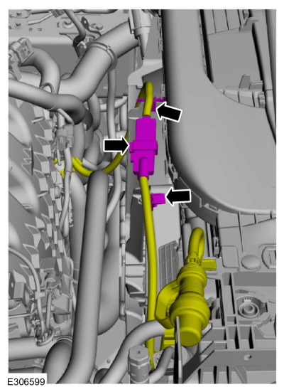
If equipped, disconnect the block heater electrical connector and detach the wiring harness retainers.
-
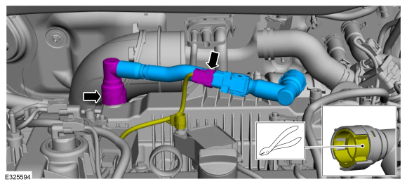
NOTE:
The crankcase vent tube may have either a permanent
or quick connect connector at one or both ends. If the tube needs to be
removed for any reason, the permanent connector(s) must be cut to remove
the tube. The tube will then need to be replaced.
NOTE:
If the crankcase vent tube is replaced, the
replacement part may not come with a crankcase pressure sensor. If so,
the PCM will need to be reprogrammed.
-
If equipped, disconnect the wiring harness electrical connector.
-
If necessary, cut the lock tab.
Use the General Equipment: Side Cutter Pliers
-
If either crankcase vent tube connector was cut, remove and discard the crankcase vent tube.
-
-
Disconnect the lower radiator hose retainer.
-
Disconnect the lower radiator hose from the thermostat housing.
Use the General Equipment: Hose Clamp Remover/Installer
-
Remove the bolt and position the A/C line bracket aside.
-
Remove the bolt, detach the wiring harness retainer and position the ground wire aside.
-
Remove the nut and position the battery feed cable from the positive battery cable.
-
Remove the bolt, detach retainer and position the ground wire aside.
-
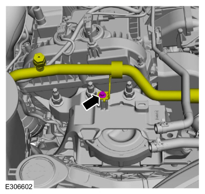
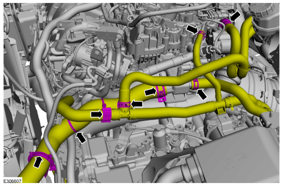
-
Detach the degas bottle coolant hose retainers.
-
Release the clamp and remove the degas bottle coolant hose.
Use the General Equipment: Hose Clamp Remover/Installer
-
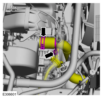
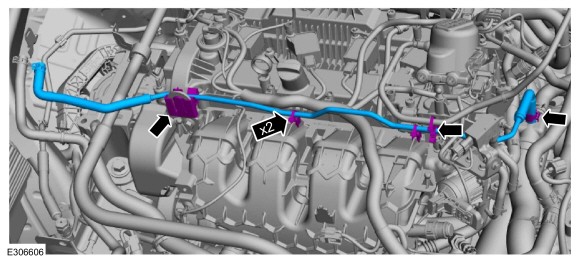
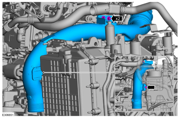
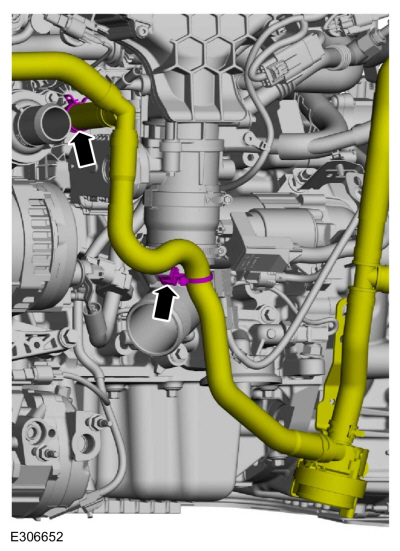
-
Detach the coolant hose retainers.
-
Disconnect heater hose from the EGR cooler.
-
Release the clamps and disconnect the coolant hoses.
Use the General Equipment: Hose Clamp Remover/Installer
-
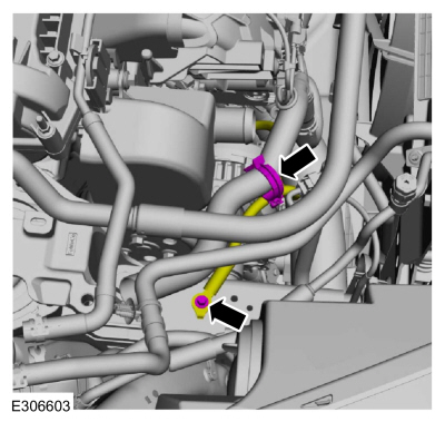
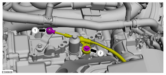
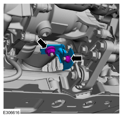
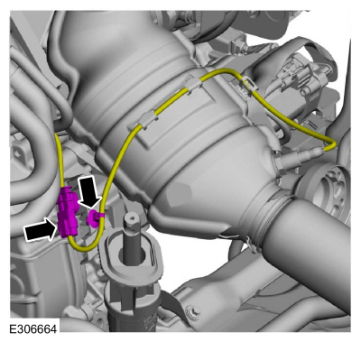
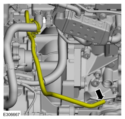
-
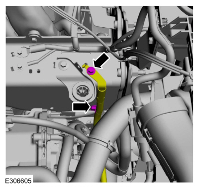
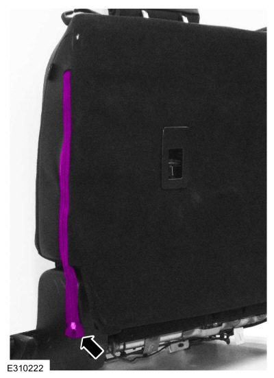
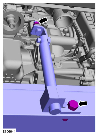
Disconnect the manual park release cable from the manual control lever.
-
Remove the bolt and position the manual park release cable aside.
-
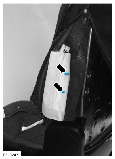
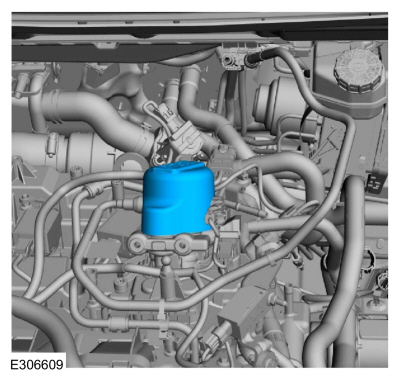
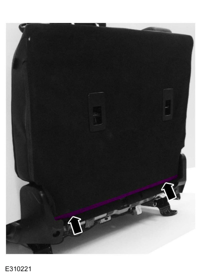
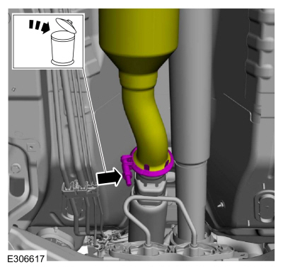
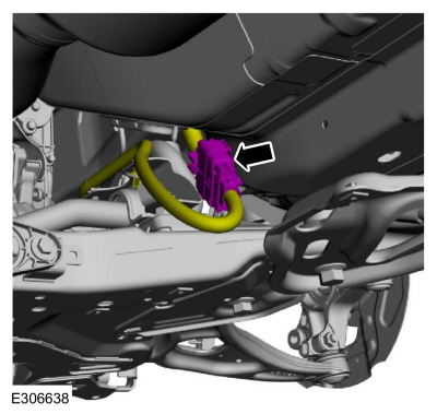
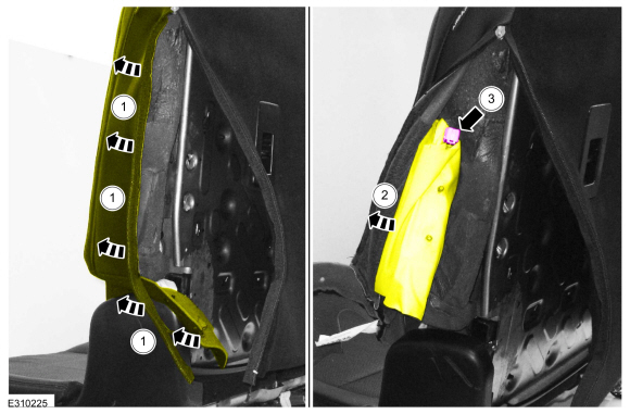
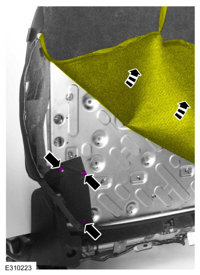
NOTE:
When removing the high-pressure fuel pump noise
insulator, spreading the openings will reduce the risk of damage.
Remove the high-pressure fuel pump noise insulator.
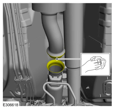
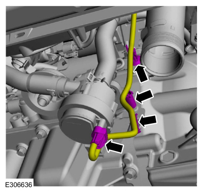
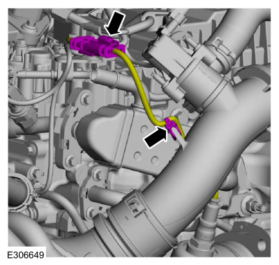
-
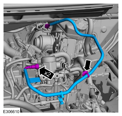
-
Detach the fuel tube retainer.
-
Disconnect the fuel tube spring lock couplings and remove the fuel tube.
-
Remove the following items:
-
Remove the front wheels and tires.
Refer to: Wheel and Tire (204-04A Wheels and Tires, Removal and Installation).
-
Remove the RH and LH front suspension height sensors.
Refer to: Front Suspension Height Sensor (204-05 Vehicle Dynamic Suspension, Removal and Installation).
-
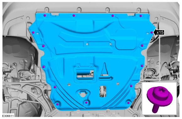
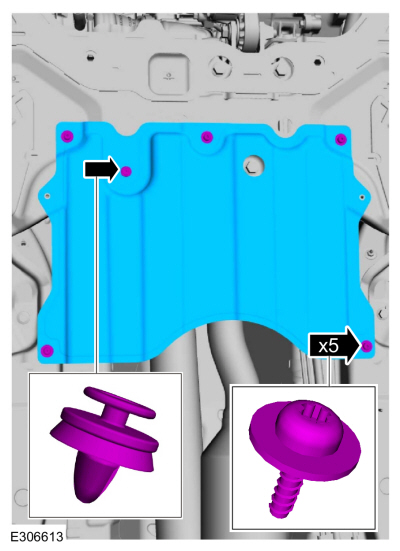
Remove the retainers and the underbody shield.
-
Remove the retainers and the underbody shields.
-
Remove the retainers and the underbody shield.
-
Remove the following items:
-
Remove the RH and LH fender splash shields.
Refer to: Fender Splash Shield (501-02 Front End Body Panels, Removal and Installation).
-
Remove the front bumper cover.
Refer to: Front Bumper Cover (501-19 Bumpers, Removal and Installation).
-
-
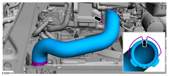
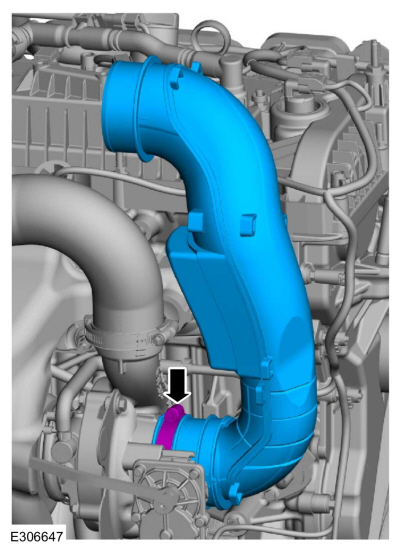
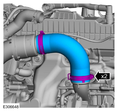
Release the CAC pipe clip.
-
Loosen the clamp and remove the outlet CAC pipe.
-
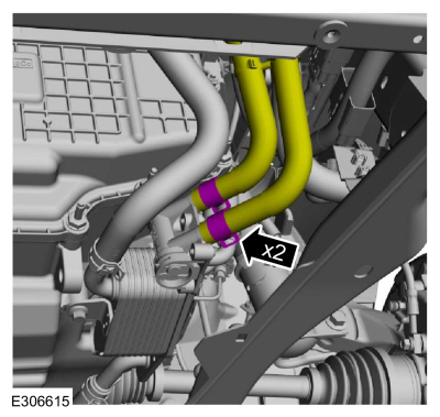
Disconnect the transmission fluid cooler tubes.
Use the General Equipment: Hose Clamp Remover/Installer
-
Remove the nuts and the catalytic converter support bracket.
LHD FWD
-
-
Loosen the clamp and position the catalytic converter back.
-
Make sure that the mating faces are clean and free of foreign material.
-
Remove the FWD RH halfshaft.
Refer to: Front Halfshaft RH - 2.0L EcoBoost (177kW/240PS) – MI4, FWD
(205-04 Front Drive Halfshafts, Removal and Installation).
LHD AWD
-
Remove the following items:
-
Remove the AWD RH halfshaft.
Refer to: Front Halfshaft RH - AWD (205-04 Front Drive Halfshafts, Removal and Installation).
-
Remove the rear driveshaft.
Refer to: Rear Driveshaft (205-01 Driveshaft, Removal and Installation).
-
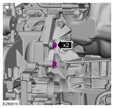
Disconnect the lower transfer case wiring harness electrical connector and retainer.
-
Remove and discard the bottom transfer case bolts.
LHD AWD/LHD FWD
-
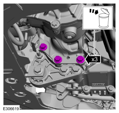
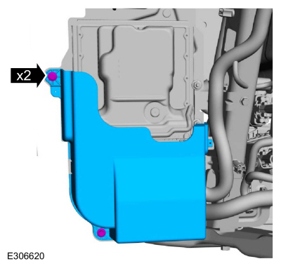
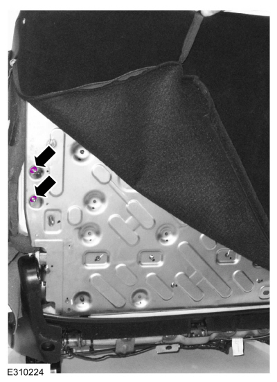
Remove the bolts and the PCM cover.
-
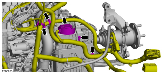
-
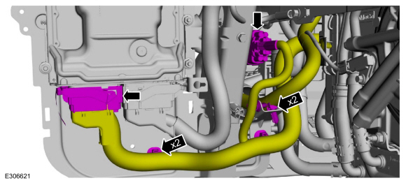
Disconnect the engine harness electrical connector and retainers.
-
Disconnect the PCM electrical connector and the retainers.
-
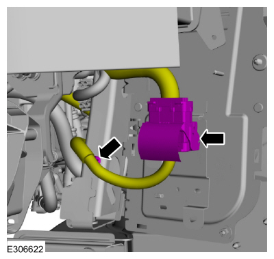
NOTE:
This connector is located on the back side of the PCM .
Disconnect the engine harness electrical connector and the wiring harness retainer.
-
NOTICE:
During the removal of components, cap, tape or
otherwise appropriately protect all openings to prevent the ingress of
dirt or other contamination. Remove protective materials prior to
installation.
-
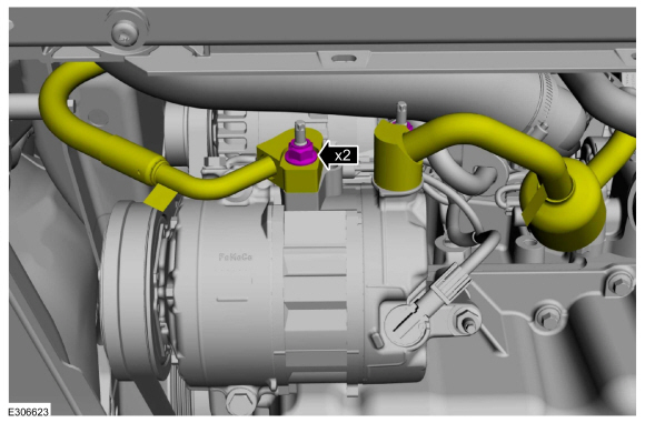
Remove the nuts and disconnect the A/C lines.
-
Discard the O-ring seals and gasket seals.
-
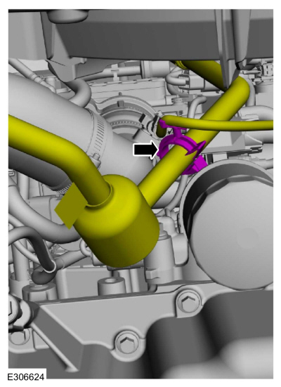
Detach the wiring harness retainer from A/C line.
-
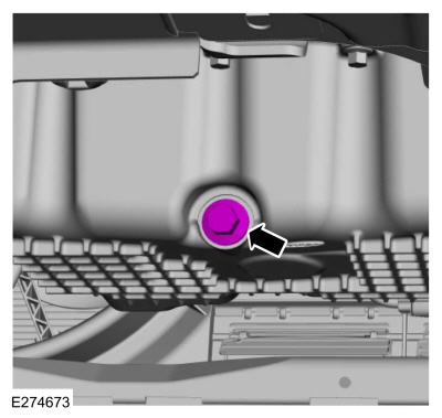
-
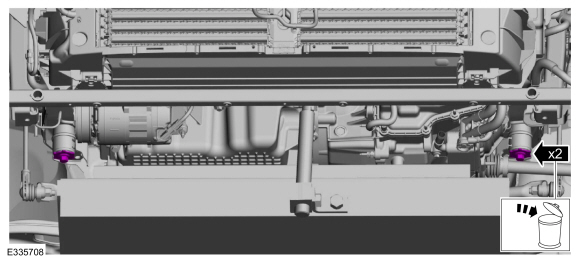
Remove the oil pan drain bolt and drain the engine oil.
Use the General Equipment: Oil Drain Equipment
-
Install the oil pan drain bolt.
Torque:
20 lb.ft (27 Nm)
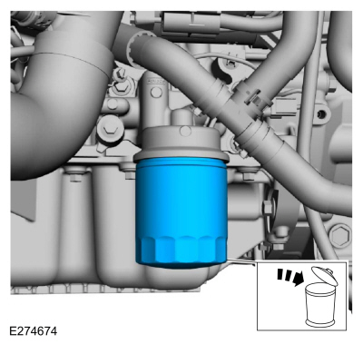
-
Remove and discard the engine oil filter.
Use the General Equipment: Oil Drain Equipment
-
-
Release the CAC pipe clip.
-
Loosen the clamp and remove the intake CAC pipe.
-
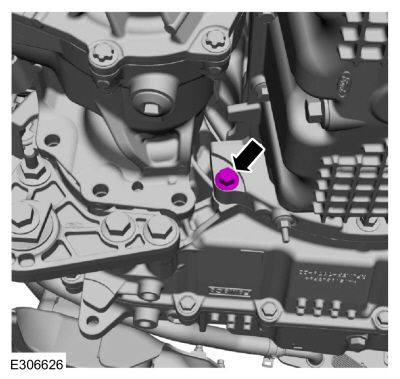
Remove the oil pan-to-transmission bolt.
-
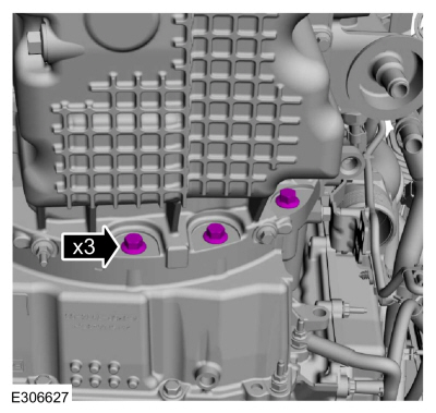
Remove the oil pan-to-transmission bolts.
-
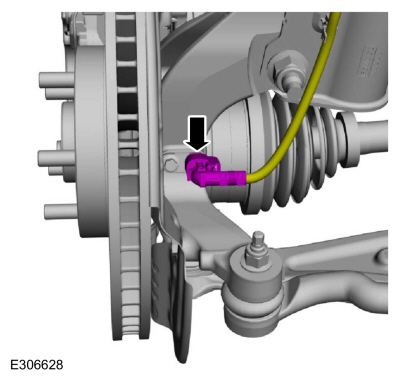
Disconnect the LH anti-lock sensor.
-
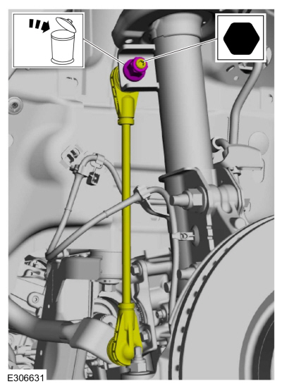
NOTICE:
Use the internal or external hex-holding feature to
prevent the ball and stud from turning while removing or installing the
stabilizer bar link nuts. The link boot seal must not be allowed to
twist while tightening the link nuts or damage to the boot seal will
occur.
Remove the nut and position the LH sway bar link aside.
-
NOTICE:
Use the internal or external hex-holding feature to
prevent the ball and stud from turning while removing or installing the
stabilizer bar link nuts. The link boot seal must not be allowed to
twist while tightening the link nuts or damage to the boot seal will
occur.
Remove the nut and position the RH sway bar link aside.
-
NOTICE:
Do not allow the brake caliper and anchor plate
assembly to hang from the brake hose or damage to the hose can occur.
Remove the LH front brake disc.
Refer to: Brake Disc (206-03 Front Disc Brake, Removal and Installation).
-
-
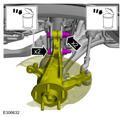
Remove the nuts and push the LH strut bolts out and remove.
-
Discard the nuts and the bolts.
-
-
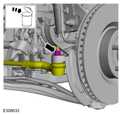
Remove the nut and disconnect the RH tie rod from the wheel knuckle.
-
-
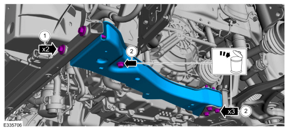
Remove the subframe support bracket bolts.
-
Remove and discard the bolts and remove the LH subframe support bracket.
-
-
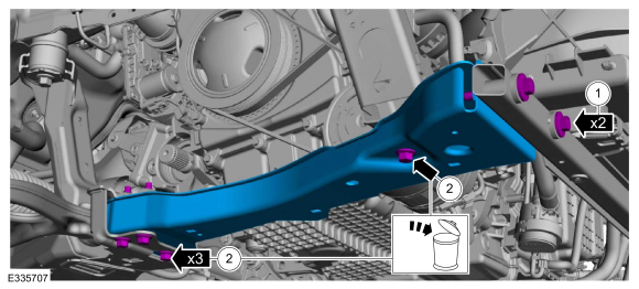
Remove the subframe support bracket bolts.
-
Remove and discard the bolts and remove the RH subframe support bracket.
-
Disconnect the steering gear electrical connector behind the RH side of subframe.
-
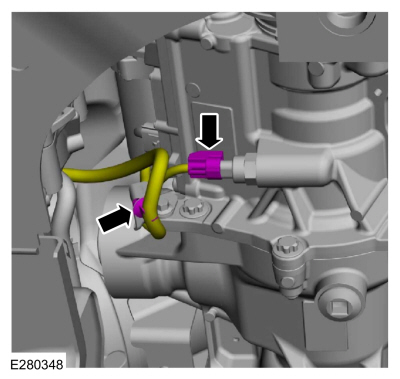
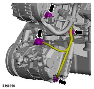
Disconnect the auxiliary coolant pump electrical connector and detach the wiring harness retainers.
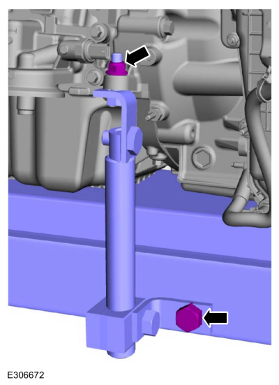
-
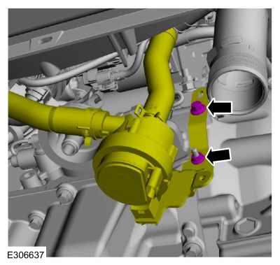
Remove the nut, bolt and position the auxiliary coolant pump aside.
-
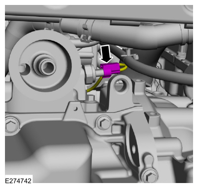
NOTE:
This will aid in the installation of the adjustable mounting arm.
Disconnect the EOP sensor electrical connector.
-
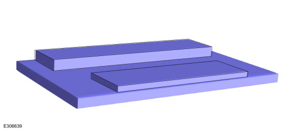
NOTE:
Board configuration may vary between vehicles.
Position a 2 x 8 board and a 1 x 4 board onto the powertrain jack as shown.
Use the General Equipment: Powertrain Jack
Use the General Equipment: Wooden Block
-
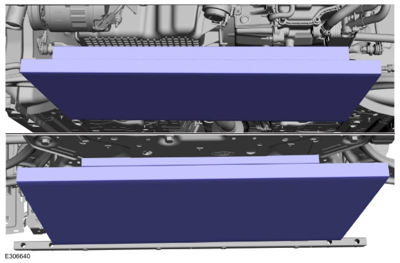
Position the powertrain jack and blocks of wood under the powertrain and subframe as shown.
Use the General Equipment: Powertrain Jack
Use the General Equipment: Wooden Block
-
NOTE:
Adjustable mounting arm configuration may vary between vehicles.
Install the adjustable mounting arm.
Use the General Equipment: Adjustable Mounting Arm
-
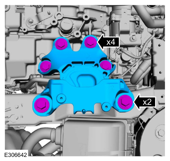
Remove the bolts and the transmission support insulator.
-
-
Remove and discard the nuts and bolts.
-
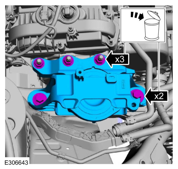
-
Remove and discard the rearward subframe bolts.
-
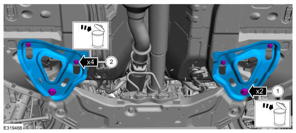
Remove and discard the bolts and remove the subframe brackets.
-
Remove and discard the forward subframe bolts.
-
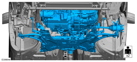
With the aid of an assistant and using the powertrain lift, lower the powertrain and subframe assembly.
-
Loosen the clamp and remove the CAC pipe.
-
Disconnect the CAC pipe bypass valve electrical connector and wire retainer.
-
Loosen the clamps and remove the CAC pipe.
-
Disconnect the HO2S electrical connector and the retainer.
-
Release the clip and remove the CAC pipe.
-
Remove the nut, bolts and the CAC pipe.
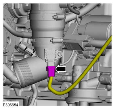
-
Release the clamp and remove from the thermostat housing and detach the retainer.
Use the General Equipment: Hose Clamp Remover/Installer
-
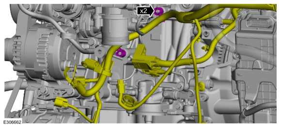
Disconnect the transmission wiring harness connector and detach the retainers.
-
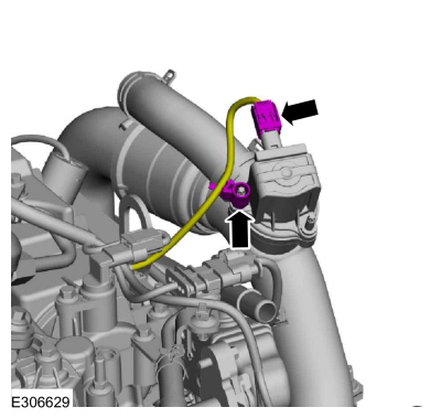
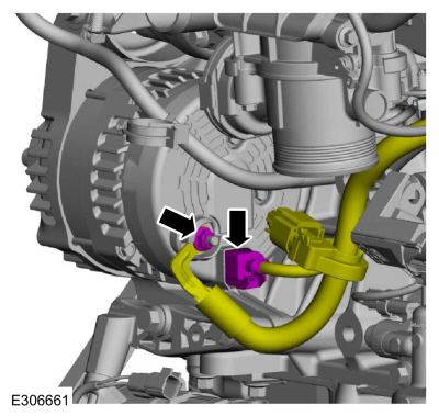
Disconnect the pressure sensor electrical connector.
-
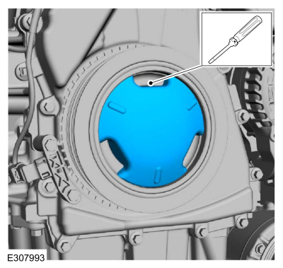
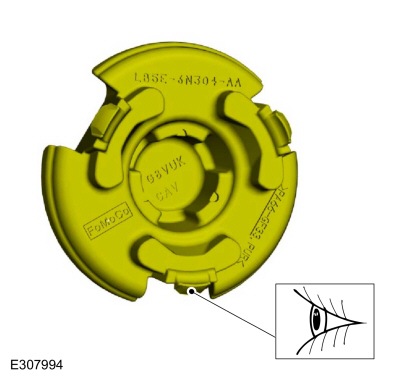
If equipped, release the tabs and remove the crankshaft pulley cover.
-
If equipped, inspect the 3 crankshaft pulley cover tabs
for damage, if damaged replace the crankshaft pulley cover.
-
-
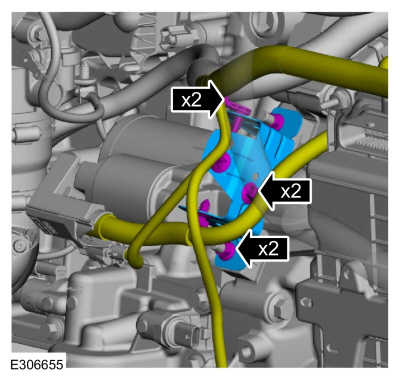
Detach the wiring harness retainers.
-
Remove the nuts and the starter motor bracket.
-
Remove the stud bolts and position the starter aside.
-
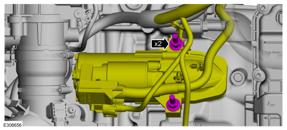
Remove the battery positive cable nut cover.
-
-
Remove the battery positive cable nut.
-
Remove the nut and disconnect the battery cable harness.
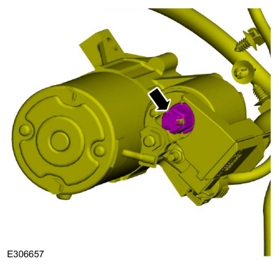
-
Remove the stater motor isolator.
-
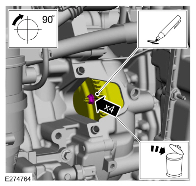
NOTE:
Only rotate the crankshaft in a clockwise direction.
-
Index mark one stud and the flexplate for assembly reference.
-
Remove and discard the torque converter nuts.
Use the General Equipment: Magnetic Socket
-
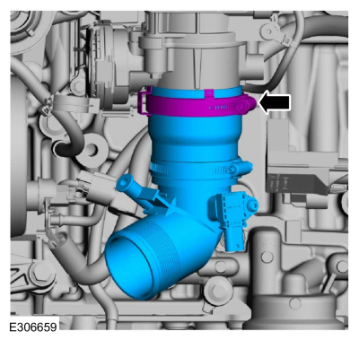
Loosen the clamp and remove the CAC outlet pipe.
-
-
Remove the generator B+ cable nut cover.
-
Disconnect the A/C compressor electrical connectors and detach the retainer.
-
-
Remove the nut and the B+ cable.
-
Disconnect the generator electrical connector.
-
Detach the generator and A/C wiring harness retainers and position the harness on the transmission.
-
Detach the wiring harness retainers from transmission stud bolts.
-
Disconnect the catalyst monitor sensor electrical connector and the retainer.
-
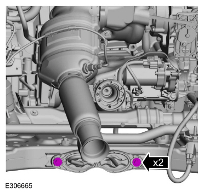
Remove the catalytic converter support bracket-to-subframe bolts.
-
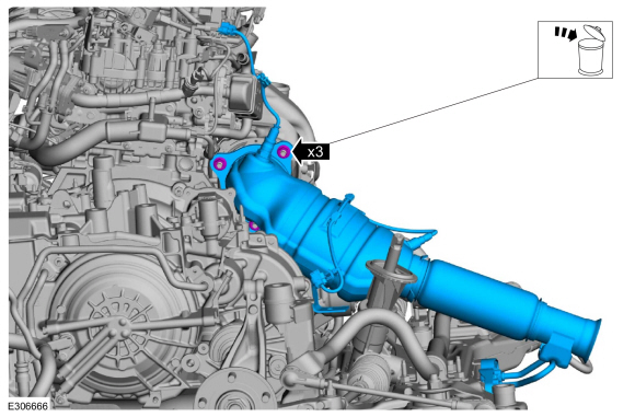
-
Remove the nuts and the catalytic converter.
-
Make sure that the mating faces are clean and free of foreign material.
-
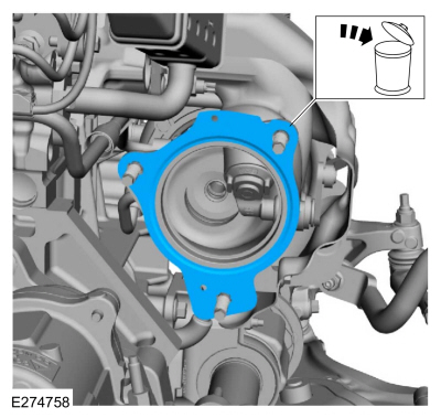
-
Remove and discard the catalytic converter gasket.
-
Make sure that the mating faces are clean and free of foreign material.
LHD AWD
-
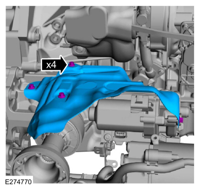
Disconnect and position aside the transfer case vent tube aside.
-
Remove the bolts and the transfer case heat shield.
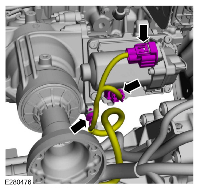
-
Disconnect the upper transfer case wiring harness electrical connectors and retainer.
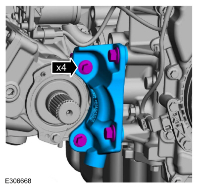
-
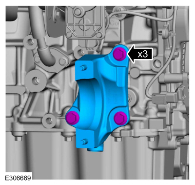
Remove the bolts and the transfer case support bracket.
-
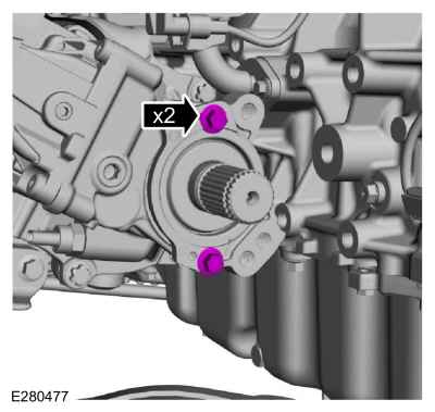
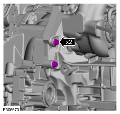
Remove the bolts for the transfer case axle shaft.
-
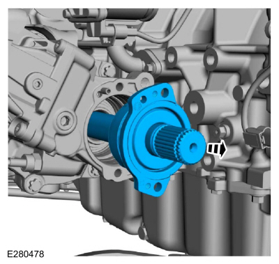
Remove the transfer case axle shaft.
-
-
Remove the bolts and the transfer case.
-
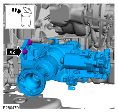
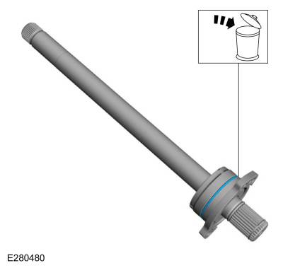
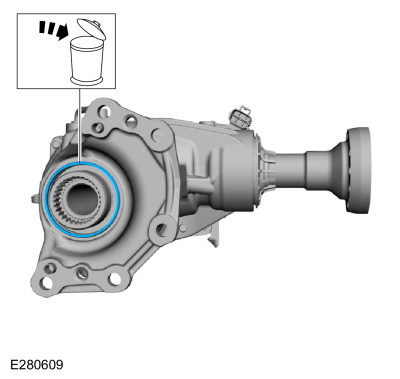
Remove and discard the transfer case axle shaft seal.
-
Remove and discard the transfer case compression seal.
-
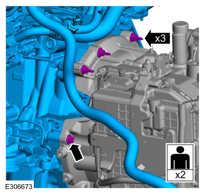
Remove the engine-to-transmission bolts.
LHD FWD
-
Remove the bolts and the halfshaft support bracket.
-
Remove the engine-to-transmission bolts.
LHD AWD/LHD FWD
-
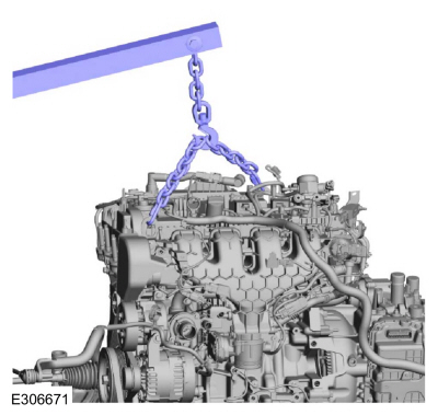
Install the engine lift equipment.
Use the General Equipment: Floor Crane
-
Remove the adjustable mounting arm.
Use the General Equipment: Adjustable Mounting Arm
-
Remove the bolt, stud bolts and with the aid of an assistant remove the engine.
-
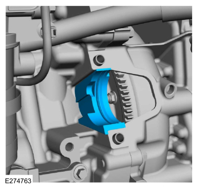
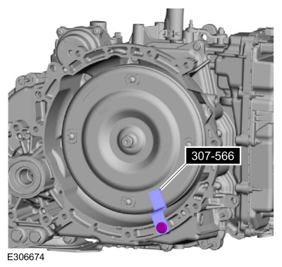
Install Special Service Tool: 307-566
Retainer, Torque Converter.
Removal
NOTICE:
During engine repair procedures, cleanliness is extremely
important. Any foreign material, including any material created while
cleaning gasket surfaces, that enters the oil passages, coolant passages
or the oil pan can cause engine failure...
Special Tool(s) /
General Equipment
205-153
(T80T-4000-W)
Handle
303-1685Alignment Tool, Camshaft
303-1687Installer, VCT Solenoid Seal
303-1689Holding Tool, Crank Damper
303-409
(T92C-6700-CH)
Remover, Crankshaft SealTKIT-1992-FH/FMH/FLMHTKIT-1993-LMH/MH
303-507Timing Peg, Crankshaft TDCTKIT-2001N-FLMTKIT-2001N-ROW
307-005
(T59L-100-B)
Slide H..
Other information:
Materials
Name
Specification
Motorcraft® MERCON® ULV Automatic Transmission FluidXT-12-QULV
WSS-M2C949-A, MERCON® ULV
Connect
With the vehicle in NEUTRAL, position it on a hoist.
Refer to: Jacking and Lifting (100-02)
.
Use the Fluid Exchanger to change the fluid.
Material: Motorcraft® MERCON® ULV Automatic Transmission Fluid
/ XT-12-QULV
(WS..
Synchronization
NOTE:
The power folding mirrors may need to be synchronized any
time the mirrors are folded or unfolded without using the exterior
mirror control switch, or if a new power folding mirror is installed.
NOTE:
The power telescoping mirrors may need to be synchronized
any time the mirrors are extended or retracted without using the
exterior mirror control switch, or if a ne..
 Removal and Installation - Variable Camshaft Timing (VCT) Unit
 Disassembly - Engine