Lincoln Corsair: Automatic Transmission - 8-Speed Automatic Transmission – 8F35/8F40 / Description and Operation - B Clutch
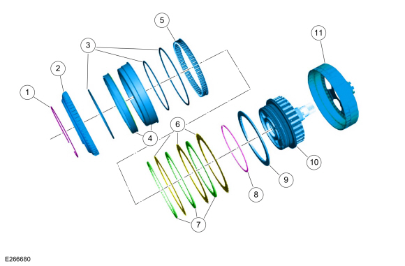
B Clutch Exploded View
| Item | Description |
| 1 | Snap ring |
| 2 | B (4, 6, R) clutch apply plate |
| 3 | B (4, 6, R) clutch piston seals |
| 4 | B (4, 6, R) clutch pistons |
| 5 | B (4, 6, R) clutch piston return spring |
| 6 | B (4, 6, R) clutch fiber plates |
| 7 | B (4, 6, R) clutch steel plates |
| 8 | Snap ring |
| 9 | B (4, 6, R) clutch pressure plate |
| 10 | B (4, 6, R)/E (5, 6, 7, 8) clutch hub |
| 11 | Reaction carrier sunshell |
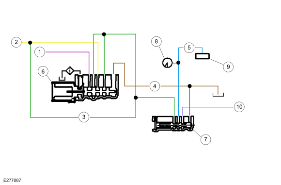
B Clutch Hydraulic Circuits
| Item | Description |
| 1 | Pump output |
| 2 | Clutch exhaust |
| 3 | B (4, 6, R) clutch control |
| 4 | Elevated exhaust |
| 5 | Apply pressure to mechanical B (4, 6, R) clutch |
| 6 | SSB /control valve |
| 7 | B (4, 6, R) clutch latch valve |
| 8 | B (4, 6, R) clutch pressure sensor |
| 9 | Mechanical B (4, 6, R) clutch |
| 10 | Pump output |
B Clutch Hydraulic Operation
Pump output pressure is supplied to the B (4, 6, R) clutch control valve. As SSB turns on, it moves the control valve allowing regulated pump output pressure to flow to the B (4, 6, R) clutch latch valve and then to the mechanical B (4, 6, R) clutch. When the regulated pump output pressure in the B (4, 6, R) clutch control circuit reaches approximately 689 kPa (100 psi), the mechanical B (4, 6, R) clutch is fully applied. The pressure in the B (4, 6, R) clutch control circuit moves the B (4, 6, R) clutch latch valve to the left allowing pump output pressure to hold the mechanical B (4, 6, R) clutch applied.
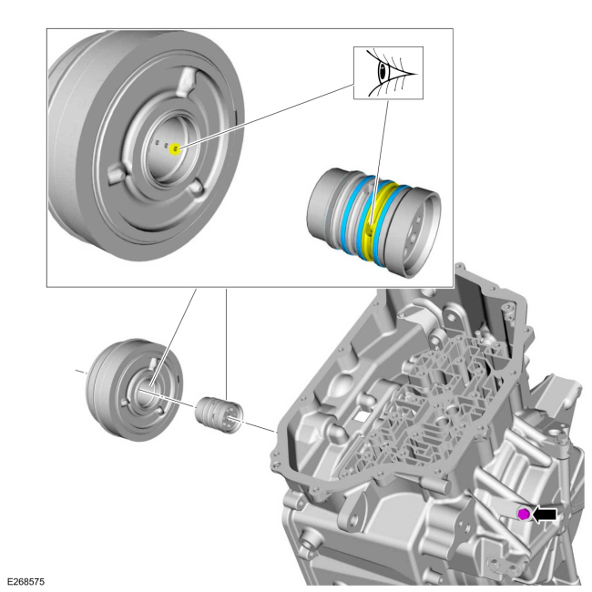
B Clutch Hydraulic Passages

 Description and Operation - C Clutch
C Clutch Exploded View
Item
Description
1
C (3, 7) clutch pressure plate
2
Sunshell
3
C (3, 7) clutch friction plates
4
C (3, 7) clutch steel plates
5
Wave spring
6
C (3, 7) clutch piston apply ring
7
Snap ring
8
C (3, 7) clutch piston return s..
Other information:
Lincoln Corsair 2020-2026 Owners Manual: Audible Warnings and Indicators
Keyless Warning Alert The horn will sound twice when you exit your vehicle with the intelligent access key and your vehicle is in RUN, indicating your vehicle is still on. Headlamps On Warning Chime Sounds when you have left the headlamps or parking lamps on and open the driver door with the vehicle off. Parking Brake On Warning Chime Sounds when you have left the parking brake on and drive ..
Lincoln Corsair 2020-2026 Owners Manual: Information Messages
Move the selector switch to the right to acknowledge and remove some messages from the information display. Other messages will be removed automatically after a short time. Certain messages need to be confirmed before you can access the menus. Active Park Adaptive Cruise Control (If Equipped) Adaptive Headlamps (If Equipped) AdvanceTrac™ and Traction Control Alarm Automatic Engine Shu..
Categories
- Manuals Home
- 1st Generation Lincoln Corsair Owners Manual
- 1st Generation Lincoln Corsair Service Manual
- Warning Lamps and Indicators
- Programming the Garage Door Opener to Your Hand-Held Transmitter
- Exterior Mirrors
- New on site
- Most important about car
360 Degree Camera Cameras
Locating the Rear View Camera

The rear view camera is on the tailgate.
Locating the Front View Camera