Lincoln Corsair: Engine - 2.0L EcoBoost (177kW/240PS) – MI4 / Removal and Installation - Valve Cover
Special Tool(s) /
General Equipment
 |
205-153
(T80T-4000-W)
Handle |
 |
303-1687
Installer, VCT Solenoid Seal |
Materials
| Name |
Specification |
Motorcraft® High Performance Engine RTV Silicone
TA-357 |
WSE-M4G323-A6
|
Removal
NOTICE:
During engine repair procedures, cleanliness is extremely
important. Any foreign material, including any material created while
cleaning gasket surfaces, that enters the oil passages, coolant passages
or the oil pan can cause engine failure.
-
With the vehicle in NEUTRAL, position it on a hoist.
Refer to: Jacking and Lifting - Overview (100-02 Jacking and Lifting, Description and Operation).
-
Release the fuel system pressure.
Refer to: Fuel System Pressure Release (310-00B Fuel System - General
Information - 2.3L EcoBoost (199kW/270PS), General Procedures).
-
Remove the air cleaner outlet pipe.
Refer to: Air Cleaner Outlet Pipe (303-12A Intake Air Distribution and
Filtering - 2.0L EcoBoost (177kW/240PS) – MI4, Removal and
Installation).
-
Remove the oil level indicator.
-
Remove the following items:
-
Remove the ignition coil-on-plugs.
Refer to: Ignition Coil-On-Plug (303-07A Engine Ignition - 2.0L
EcoBoost (177kW/240PS) – MI4/2.0L EcoBoost (184kW/250PS) – MI4, Removal
and Installation).
-
Remove the high-pressure fuel pump.
Refer to: High-Pressure Fuel Pump (303-04B Fuel Charging and Controls - 2.3L EcoBoost (199kW/270PS), Removal and Installation).
-
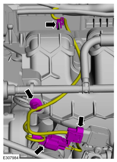
Position the EVAP canister purge valve tubes aside.
-
-
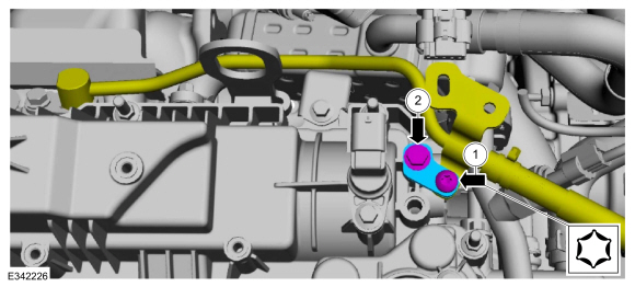
Detach the fuel tube retainer.
-
Remove the nut and position the fuel tube and bracket aside.
-
-
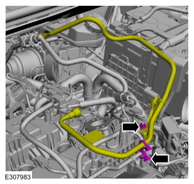
Disconnect the MAPT sensor wiring harness electrical connector.
-
Disconnect the KS wiring harness electrical connector.
-
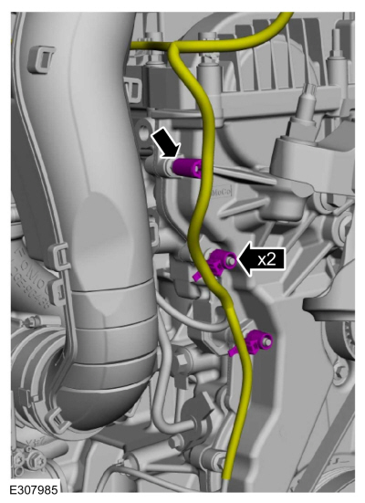
Detach the wiring harness retainers.
-
Detach the wiring harness retainers from the front cover stud bolts.
-
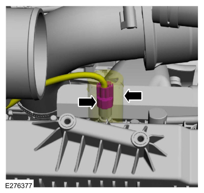
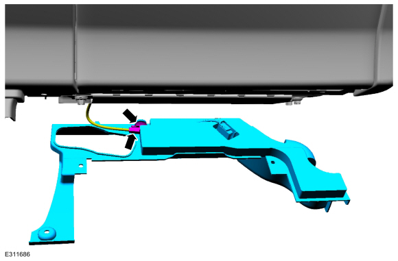
Slide the insulator up and disconnect the CHT sensor wiring harness electrical connector.
-
-
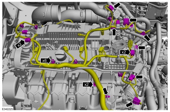
Disconnect the wiring harness electrical connectors.
-
Detach the wiring harness retainers.
-
Position the wiring harness aside.
-
-
Remove the coolant tube bracket bolt.
-
Remove the coolant tube bolt and the bracket.
-
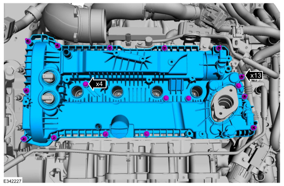
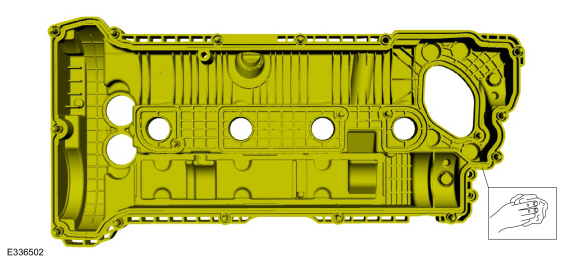
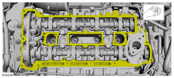
Loosen the fasteners and remove the valve cover.
-
Remove and discard the valve cover gaskets.
-
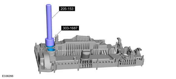
NOTE:
The VCT solenoid seals should only be replaced if they are damaged.
-
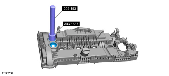
Inspect the VCT oil control solenoid seals for damage.
-
If damaged, using the special tools, remove and discard the VCT oil control solenoid seals.
Use Special Service Tool: 205-153
(T80T-4000-W)
Handle.
, 303-1687
Installer, VCT Solenoid Seal.
-
NOTICE:
Do not use metal scrapers, wire brushes, power
abrasive discs or other abrasive means to clean the sealing surfaces.
These tools cause scratches and gouges which make leak paths.
Make sure that the mating faces are clean and free of foreign material.
-
NOTICE:
Do not use metal scrapers, wire brushes, power
abrasive discs or other abrasive means to clean the sealing surfaces.
These tools cause scratches and gouges which make leak paths.
Make sure that the mating faces are clean and free of foreign material.
Installation
-
NOTE:
Installation of new seals is only required if damaged seals were removed during removal.
If removed, using the special tools, install the VCT oil control solenoid seals.
Use Special Service Tool: 205-153
(T80T-4000-W)
Handle.
, 303-1687
Installer, VCT Solenoid Seal.
-
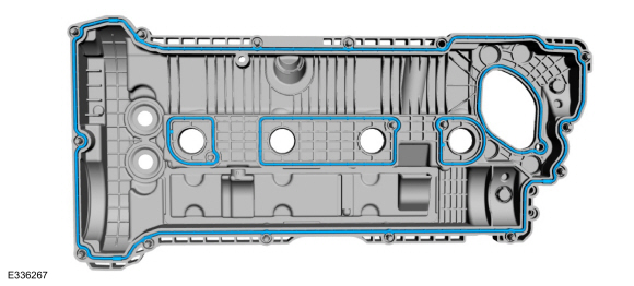
Install a new valve cover gaskets.
-
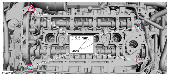
Apply a 5.5 mm (0.22 in) bead of silicone sealant in the 4 places shown.
Material: Motorcraft® High Performance Engine RTV Silicone
/ TA-357
(WSE-M4G323-A6)
-
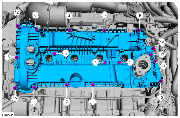
NOTE:
The valve cover must be secured within 10 minutes of
silicone gasket application. If the valve cover is not secured within
10 minutes, the sealant must be removed and the sealing area cleaned.
Install the valve cover and tighten the fasteners in sequence shown.
Torque:
97 lb.in (11 Nm)
-
-
Install the coolant tube bracket and the bolt.
Torque:
97 lb.in (11 Nm)
-
Install the coolant tube bracket bolt.
Torque:
53 lb.in (6 Nm)
-
-
Position the wiring harness.
-
Attach the wiring harness retainers.
-
Connect the wiring harness electrical connectors.
-
Connect the CHT sensor wiring harness electrical connector and slide the insulator down.
-
Attach the wiring harness retainers to the front cover stud bolts.
-
-
Attach the wiring harness retainers.
-
Connect the KS wiring harness electrical connector.
-
Connect the MAPT sensor wiring harness electrical connector.
-
-
Position the fuel tube and bracket and install the nut.
Torque:
89 lb.in (10 Nm)
-
Attach the fuel tube retainer.
-
Position the EVAP canister purge valve tubes back to there original position.
-
Install the following items:
-
Install the high-pressure fuel pump.
Refer to: High-Pressure Fuel Pump (303-04B Fuel Charging and Controls - 2.3L EcoBoost (199kW/270PS), Removal and Installation).
-
Install the ignition coil-on-plugs.
Refer to: Ignition Coil-On-Plug (303-07A Engine Ignition - 2.0L
EcoBoost (177kW/240PS) – MI4/2.0L EcoBoost (184kW/250PS) – MI4, Removal
and Installation).
-
Install the oil level indicator.
-
Install the air cleaner outlet pipe.
Refer to: Air Cleaner Outlet Pipe (303-12A Intake Air Distribution and
Filtering - 2.0L EcoBoost (177kW/240PS) – MI4, Removal and
Installation).
-
Pressurize the fuel system.
Refer to: Fuel System Pressure Release (310-00B Fuel System - General
Information - 2.3L EcoBoost (199kW/270PS), General Procedures).
Removal
NOTICE:
Do not loosen or remove the crankshaft pulley bolt without
first installing the special tools as instructed in this procedure. The
crankshaft pulley and the crankshaft timing sprocket are not keyed to
the crankshaft...
Removal
Remove the camshafts.
Refer to: Camshafts (303-01A Engine - 2.0L EcoBoost (177kW/240PS) – MI4, Removal and Installation).
If the camshafts and valve tappets are to be reused,
make sure they are assembled in their original positions...
Other information:
Special Tool(s) /
General Equipment
Interior Trim Remover
Removal
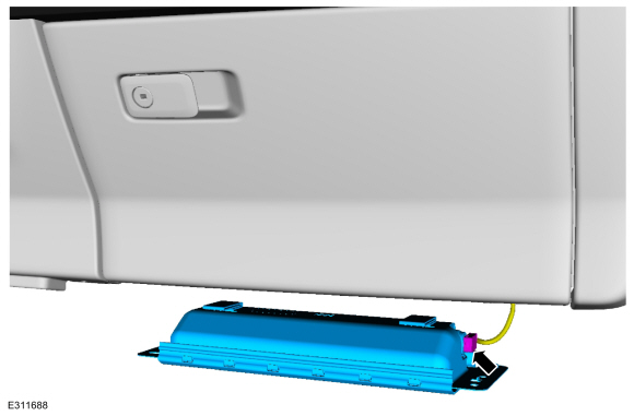
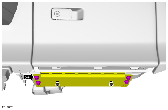
Release the clips and remove the rear scuff plate trim panel.
Use the General Equipment: Interior Trim Remover
Installation
To install, reverse the removal procedure...
Removal
NOTE:
Left hand (LH) shown, right hand (RH) similar.
NOTE:
For front door window regulator motors that are
non-functional it may be necessary to remove the front door window
regulator motor prior to securing the front door window glass...
Categories
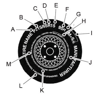
P215/65R15 95H is an example of a tire
size, load index and speed rating. The
definitions of these items are listed
below. (Note that the tire size, load index
and speed rating for your vehicle may
be different from this example.)
P: Indicates a tire, designated by the
Tire and Rim Association, that may be
used for service on cars, sport utility
vehicles, minivans and light trucks. Note:
If your tire size does not begin with a
letter this may mean it is designated by
either the European Tire and Rim
Technical Organization or the Japan Tire
Manufacturing Association.
215: Indicates the nominal width of
the tire in millimeters from sidewall edge
to sidewall edge. In general, the larger
the number, the wider the tire.
65: Indicates the aspect ratio which
gives the tire's ratio of height to width.
R: Indicates a radial type tire.
15: Indicates the wheel or rim
diameter in inches. If you change your
wheel size, you will have to purchase
new tires to match the new wheel
diameter.
95: Indicates the tire's load index. It
is an index that relates to how much
weight a tire can carry. You may find this
information in your owner’s manual. If
not, contact a local tire dealer.
read more


 Removal and Installation - Timing Chain Tensioner
 Removal and Installation - Valve Tappets