Lincoln Corsair: Fuel Charging and Controls - Turbocharger - 2.0L EcoBoost (177kW/240PS) – MI4 / Removal and Installation - Turbocharger Oil Supply Tube
Materials
| Name | Specification |
|---|---|
| Motorcraft® Metal Brake Parts Cleaner PM-4-A, PM-4-B, APM-4-C |
- |
Removal
NOTICE: The turbocharger compressor vanes can be damaged by even the smallest particles. When removing any turbocharger or engine air intake system component, ensure that no debris enters the system. Failure to do so may result in damage to the turbocharger.
NOTICE: Special attention needs to be given to the sealing ports for the oil feed, the oil drain, and the coolant lines, on turbocharged engines. The sealing ports must be totally clean and free from O-ring residue, have no damage to the sealing surface and the lines to ensure that there are no leaks or repeat repairs.
-
Remove the upper air cleaner outlet pipe.
Refer to: Air Cleaner Outlet Pipe (303-12A Intake Air Distribution and Filtering - 2.0L EcoBoost (177kW/240PS) – MI4, Removal and Installation).
-
Disconnect the turbocharger bypass valve electrical
connector, then detach the harness retainer from the stud bolt. Release
the charge air cooler upper inlet pipe retaining clip. Loosen the charge
air cooler upper inlet pipe clamp, then remove the charge air cooler
upper inlet pipe.
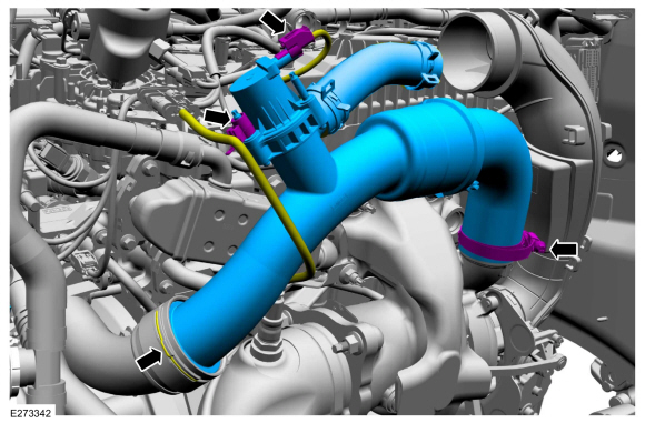 |
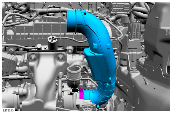
-
Loosen the lower air cleaner outlet pipe clamp, then remove the lower air cleaner outlet pipe.
 |
-
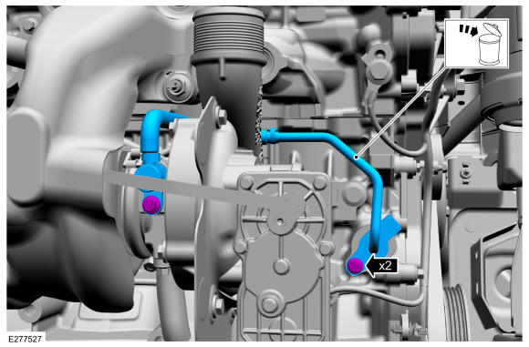
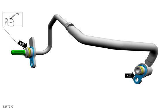
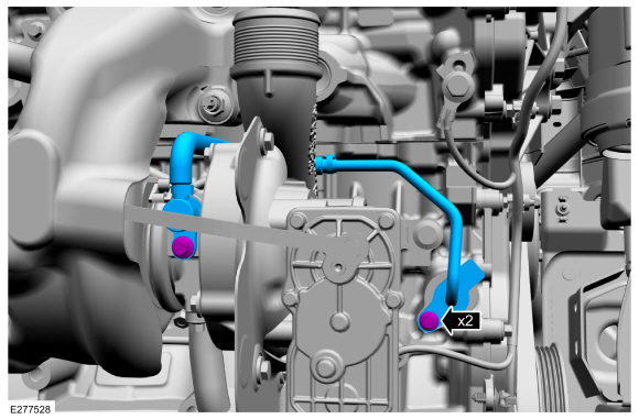
Remove the bolts, then remove and discard the
turbocharger oil supply tube.
 |
Installation
-
NOTICE: Do not reuse the turbocharger oil filter, a new turbocharger oil filter must be used.
NOTICE: Ensure that new turbocharger oil supply tube O-rings and gaskets are used.
Install the new turbocharger oil supply tube O-rings, gaskets and oil filter if not already installed. Lubricate the O-ring seals with clean engine oil.
Refer to: Specifications (303-01A Engine - 2.0L EcoBoost (177kW/240PS) – MI4, Specifications).
 |
-
NOTE: The oil supply tube must be fully seated prior to fastener tightening.
-
NOTICE: Do not use a metal brush, damage to sealing area will result in leaks.
Carefully use a nylon brush to remove the old O-ring residue, use brake cleaner to rinse the O-ring residue out of the turbocharger and engine O-ring bores. Inspect the area for deep scratches and gouges. Install new components if needed.
Material: Motorcraft® Metal Brake Parts Cleaner / PM-4-A, PM-4-B, APM-4-C
-
Install and fully seat the turbocharger oil supply tube, then install and tighten the bolts.
Torque: 97 lb.in (11 Nm)
-
 |
-
Install the lower air cleaner outlet pipe, then tighten the lower air cleaner outlet pipe clamp.
Torque: 44 lb.in (5 Nm)
|
-
Install the charge air cooler upper inlet pipe, then
tighten the clamp. Engage the charge air cooler upper intake pipe
retaining clip. Attach the harness retainer to the stud bolt, then
connect the turbocharger bypass valve electrical connector.
Torque: 44 lb.in (5 Nm)
|
-
Install the upper air cleaner outlet pipe.
Refer to: Air Cleaner Outlet Pipe (303-12A Intake Air Distribution and Filtering - 2.0L EcoBoost (177kW/240PS) – MI4, Removal and Installation).
-
Check the engine oil level and fill as needed.
Refer to: Specifications (303-01A Engine - 2.0L EcoBoost (177kW/240PS) – MI4, Specifications).
 Removal and Installation - Turbocharger Oil Return Tube
Materials
Name
Specification
Motorcraft® Metal Brake Parts CleanerPM-4-A, PM-4-B, APM-4-C
-
Removal
NOTICE:
The turbocharger compressor vanes can be damaged by even the
smallest particles...
 Removal and Installation - Wastegate Control Actuator
Removal
NOTICE:
The turbocharger compressor vanes can be damaged by even the
smallest particles. When removing any turbocharger or engine air intake
system component, ensure that no debris enters the system...
Other information:
Lincoln Corsair 2020-2026 Service Manual: Removal and Installation - Rear Window Wiper Motor
Removal NOTE: Removal steps in this procedure may contain installation details. Remove the rear window wiper pivot arm. Refer to: Rear Window Wiper Pivot Arm (501-16) . Remove the liftgate trim panel. Refer to: Liftgate Trim Panel (501-05) ...
Lincoln Corsair 2020-2026 Service Manual: Description and Operation - Differential
Differential Exploded View Item Description 1 Roll pin 2 Pinion shaft 3 Pinion gears 4 Side gears 5 Differential housing Differential Cutaway View and External Sealing Item Description 1 LH halfshaft seal 2 ..
Categories
- Manuals Home
- 1st Generation Lincoln Corsair Owners Manual
- 1st Generation Lincoln Corsair Service Manual
- Technical Specifications
- Selecting a Drive Mode. DRIVE MODES
- Memory Function
- New on site
- Most important about car
USB Port
WARNING: Driving while distracted can result in loss of vehicle control, crash and injury. We strongly recommend that you use extreme caution when using any device that may take your focus off the road. Your primary responsibility is the safe operation of your vehicle. We recommend against the use of any hand-held device while driving and encourage the use of voice-operated systems when possible. Make sure you are aware of all applicable local laws that may affect the use of electronic devices while driving.
USB A