Lincoln Corsair: Automatic Transmission - 8-Speed Automatic Transmission – 8F35/8F40 / Removal and Installation - Transmission Range (TR) Sensor
Lincoln Corsair 2020-2024 Service Manual / Powertrain / Automatic Transmission / Automatic Transmission - 8-Speed Automatic Transmission – 8F35/8F40 / Removal and Installation - Transmission Range (TR) Sensor
Special Tool(s) / General Equipment
| Punch |
Removal
-
Remove the main control valve body.
Refer to: Main Control Valve Body (307-01A Automatic Transmission - 8-Speed Automatic Transmission – 8F35/8F40, Removal and Installation).
-
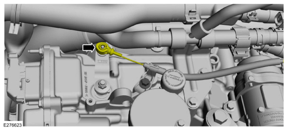
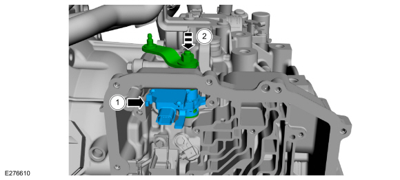
Disconnect the manual park release cable from the manual control lever.
 |
-
NOTE: Do not rotate the park rod shaft after the support bracket and spring are removed. You can over stroke the rod and it will go over the park pawl and stop you from pulling it back to gain access to the roll pin. Use a screw driver to push pawl down, then rotate the rod back if necessary.
Remove the bolt and position aside the park-by-wire support bracket and spring.
 |
-
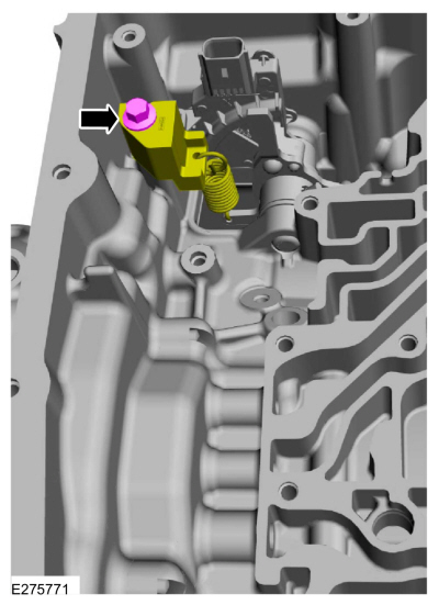
Secure the manual control shaft and lever to the transmission case with a strip clamp.
 |
-
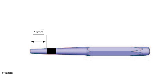
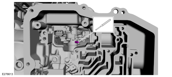
Using a 5/32 punch, measure 16mm from the tip and apply several layers of electrical tape.
Use the General Equipment: Punch
 |
-
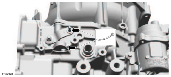
NOTE: Roll pin may fall into transmission case if driven more than 16mm.
Using a 5/32 drift punch, carefully drive the TR sensor roll pin into the manual control shaft 16mm.
Use the General Equipment: Punch
 |
-
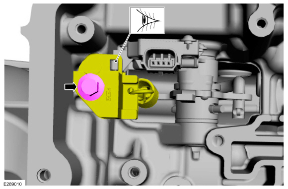
Remove the TR sensor.
-
Remove the manual control shaft and lever.
-
Remove the TR sensor and the park pawl actuator rod as an assembly
-
Remove the manual control shaft and lever.
 |
Installation
-
NOTE: Make sure the actuator rod is positioned inside the park pawl rod guide.
Install the TR sensor.
-
Install the TR sensor and park pawl actuator rod as an assembly.
-
Install the manual control shaft and lever.
-
Install the TR sensor and park pawl actuator rod as an assembly.
 |
-
Install the TR sensor roll pin.
|
-
NOTE: Make sure the transmission range sensor is aligned with the park-by-wire support bracket.
Position the park-by-wire support bracket, the spring and install the bolt.
Torque: 97 lb.in (11 Nm)
 |
-
Connect the manual park release cable to the manual control lever.
|
-
Install the main control valve body.
Refer to: Main Control Valve Body (307-01A Automatic Transmission - 8-Speed Automatic Transmission – 8F35/8F40, Removal and Installation).
 Removal and Installation - Transmission Internal Wiring Harness Frame
Removal
Remove the main control cover.
Refer to: Main Control Cover (307-01A Automatic Transmission - 8-Speed
Automatic Transmission – 8F35/8F40, Removal and Installation)...
 Removal and Installation - Transmission Support Insulator
Special Tool(s) /
General Equipment
303-F070Support Bar, EngineTKIT-1999A-F/LTTKIT-1999A-FM/FLM
Removal
With the vehicle in NEUTRAL, position it on a hoist...
Other information:
Lincoln Corsair 2020-2024 Service Manual: General Procedures - Clockspring Adjustment
Special Tool(s) / General Equipment Adhesive Tape WARNING: If the clockspring is not correctly centralized, it may fail prematurely. If in doubt, repeat the centralizing procedure. Failure to follow these instructions may increase the risk of serious personal injury or death in a crash...
Lincoln Corsair 2020-2024 Service Manual: Removal and Installation - Rear Floor Panel Section
Special Tool(s) / General Equipment Scraper for Straight Edges Spherical Cutter Hot Air Gun Air Body Saw 8 mm Drill Bit MIG/MAG Welding Equipment Spot Weld Drill Bit Locking Pliers Materials Name Specification Seam SealerTA-2-B, 3M™ 08308, LORD Fusor® 803DTM - Removal WARNING: Electric vehicles damaged by a crash ma..
Categories
- Manuals Home
- 1st Generation Lincoln Corsair Owners Manual
- 1st Generation Lincoln Corsair Service Manual
- Capacities and Specifications - 2.0L
- Head Up Display
- Child Safety Locks
- New on site
- Most important about car
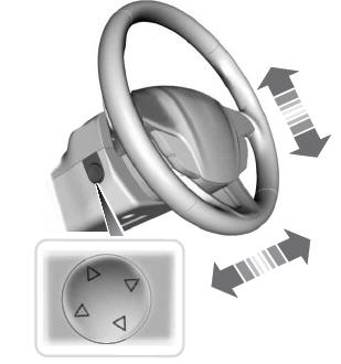
Adjusting the Steering Wheel - Vehicles With: Power Adjustable Steering Column
WARNING: Do not adjust the steering wheel when your vehicle is moving.
Note: Make sure that you are sitting in the correct position.
Copyright © 2024 www.licorsair.com