Lincoln Corsair: Fuel Charging and Controls - 2.0L EcoBoost (177kW/240PS) – MI4 / Removal and Installation - Throttle Body
Lincoln Corsair 2020-2026 Service Manual / Powertrain / Engine / Fuel Charging and Controls - 2.0L EcoBoost (177kW/240PS) – MI4 / Removal and Installation - Throttle Body
Removal
-
Remove the charge air cooler (CAC) outlet pipe.
Refer to: Charge Air Cooler (CAC) Outlet Pipe (303-12A Intake Air Distribution and Filtering - 2.0L EcoBoost (177kW/240PS) – MI4, Removal and Installation).
Refer to: Charge Air Cooler (CAC) Outlet Pipe (303-12B Intake Air Distribution and Filtering - 2.3L EcoBoost (199kW/270PS), Removal and Installation).
-
NOTE: When disconnecting the throttle body electrical connector disengage the red locking tab on the throttle body electrical connector by sliding it to the rear of the throttle body electrical connector, away from the throttle body. Squeeze the throttle body electrical connector while removing.
Disconnect the throttle body electrical connector, then detach the throttle body wire retainer.
 |
-
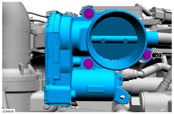
Remove the throttle body bolts, then remove the throttle body.
 |
Installation
-
Inspect the throttle body gasket, clean or replace as needed. Clean the mating surfaces.
 |
-
Install the throttle body, then install and tighten the throttle body bolts in the sequence shown.
Torque: 89 lb.in (10 Nm)
 |
-
NOTE: When connecting the throttle body electrical connector engage the red connector locking tab after fully installing the throttle body electrical connector. The red tab will not slide forward unless the throttle body electrical connector is fully installed.
Connect the throttle body electrical connector. Attach the throttle body wire retainer.
|
-
Install the charge air cooler (CAC) outlet pipe.
Refer to: Charge Air Cooler (CAC) Outlet Pipe (303-12A Intake Air Distribution and Filtering - 2.0L EcoBoost (177kW/240PS) – MI4, Removal and Installation).
Refer to: Charge Air Cooler (CAC) Outlet Pipe (303-12B Intake Air Distribution and Filtering - 2.3L EcoBoost (199kW/270PS), Removal and Installation).
-
Road test the vehicle.
 Removal and Installation - High-Pressure Fuel Pump Drive Unit
Removal
Remove the valve cover.
Refer to: Valve Cover (303-01A Engine - 2.0L EcoBoost (177kW/240PS) – MI4, Removal and Installation).
Remove the high-pressure fuel pump drive unit bolts, then remove the high-pressure fuel pump drive unit...

Other information:
Lincoln Corsair 2020-2026 Service Manual: Removal and Installation - Rear Seat Cushion Cover
Special Tool(s) / General Equipment Hog Ring Plier Removal NOTE: LH (left hand) shown, RH (right hand) similar. Remove the rear seat. Refer to: Rear Seat (501-10B Rear Seats, Removal and Installation). Release the retaining tabs and remove the lower child safety seat tether anchor bezels. Release the rear seat cushion substr..
Lincoln Corsair 2020-2026 Service Manual: Description and Operation - Rear Electric Drive Assembly - Overview
Overview The center of the electric motor control system is a microprocessor called the Secondary Inverter System Controller (S-ISC), also known as the SOBDMB . The Secondary Inverter System Controller (S-ISC) receives inputs from sensors and other electronic components. Based on information received and programmed into its memory, the Secondary Inverter System Controller (S-ISC) generates ..
Categories
- Manuals Home
- 1st Generation Lincoln Corsair Owners Manual
- 1st Generation Lincoln Corsair Service Manual
- Head Up Display
- Technical Specifications
- Auto-Start-Stop
- New on site
- Most important about car
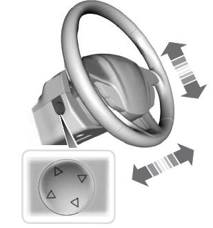
Adjusting the Steering Wheel - Vehicles With: Power Adjustable Steering Column
WARNING: Do not adjust the steering wheel when your vehicle is moving.
Note: Make sure that you are sitting in the correct position.
Copyright © 2026 www.licorsair.com