Lincoln Corsair: Steering Column / Removal and Installation - Steering Column Shaft
Removal
NOTE: Removal steps in this procedure may contain installation details.
-
NOTICE: Do not allow the steering wheel to rotate while the steering column shaft is disconnected or damage to the clockspring may result. If there is evidence that the shaft has rotated, remove and recenter the clockspring.
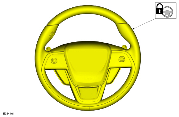
Secure the steering wheel.
 |
-
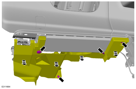
Remove the retainers and lower the driver side insulator panel.
 |
-
Remove the driver side insulator panel.
-
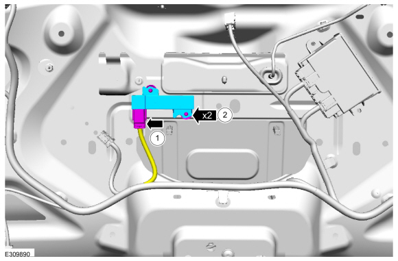
Disconnect the electrical connector.
-
Detach the pin-type retainers and position the harness aside.
-
Disconnect the electrical connector.
 |
-
 WARNING:
Do not reuse steering column shaft bolts. This may
result in fastener failure and steering column shaft detachment or loss
of steering control. Failure to follow this instruction may result in
serious injury to vehicle occupant(s).
WARNING:
Do not reuse steering column shaft bolts. This may
result in fastener failure and steering column shaft detachment or loss
of steering control. Failure to follow this instruction may result in
serious injury to vehicle occupant(s).
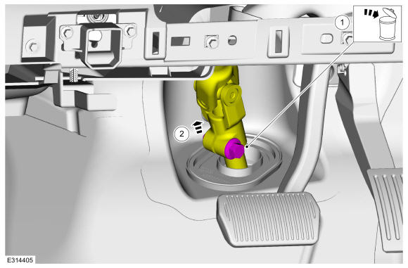
Separate the steering column shaft from the steering gear.
-
Remove and discard the steering shaft coupler retainer.
Torque: 46 lb.ft (63 Nm)
-
Separate the steering column shaft from the steering gear.
-
Remove and discard the steering shaft coupler retainer.
 |
-
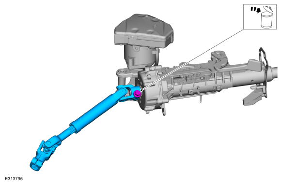
Remove and discard the steering shaft coupler retainer and remove the steering column intermediate shaft.
WARNING:
Do not reuse steering column shaft bolts. This may
result in fastener failure and steering column shaft detachment or loss
of steering control. Failure to follow this instruction may result in
serious injury to vehicle occupant(s).
Torque:
Stage 1: 35 lb.ft (48 Nm)
Stage 2: 120°
 |
Installation
-
To install, reverse the removal procedure.
 Removal and Installation - Steering Column
Removal
NOTICE:
To prevent damage to the clockspring, make sure the front wheels are in the straight-ahead position.
NOTICE:
Precise tolerances are required when manufacturing a
steering column...
 Removal and Installation - Steering Wheel
Special Tool(s) /
General Equipment
Adhesive Tape
Removal
NOTICE:
To prevent damage to the clockspring, make sure the front wheels are in the straight-ahead position...
Other information:
Lincoln Corsair 2020-2026 Service Manual: Description and Operation - Parking Brake - Overview
Overview The parking brake system uses 2 switch activated, Electronic Control Unit (ECU) controlled motors to apply and release the rear brake calipers. The ABS module controls and monitors the parking brake system and sets Diagnostic Trouble Codes (DTCs) when a fault is present in the system...
Lincoln Corsair 2020-2026 Service Manual: Removal and Installation - Block Heater
Removal NOTE: Removal steps in this procedure may contain installation details. Drain the cooling system. Refer to: Engine Cooling System Draining, Vacuum Filling and Bleeding (303-03A Engine Cooling - 2.0L EcoBoost (177kW/240PS) – MI4, General Procedures)...
Categories
- Manuals Home
- 1st Generation Lincoln Corsair Owners Manual
- 1st Generation Lincoln Corsair Service Manual
- Fuel Quality - Gasoline
- Warning Lamps and Indicators
- Technical Specifications
- New on site
- Most important about car
Second Stage: Checking Tire Pressure
WARNING: If the tire does not inflate to the recommended tire pressure within 15 minutes, stop and call roadside assistance.
WARNING: The power plug may get hot after use and should be handled carefully when unplugging.
Check the air pressure of your tires as follows: