Lincoln Corsair: Steering Column / Removal and Installation - Steering Column
Removal
NOTICE: To prevent damage to the clockspring, make sure the front wheels are in the straight-ahead position.
NOTICE: Precise tolerances are required when manufacturing a steering column. Never install a repaired, rebuilt, aftermarket, or remanufactured steering column. Always install a new steering column. Failure to follow this direction can result in steering column failure.
NOTE: Removal steps in this procedure may contain installation details.
-
NOTE: This step is only necessary when installing a new component.
If installing a new steering column, connect the scan tool and upload the module configuration information from the PSCM .
Refer to: Module Configuration - System Operation and Component Description (418-01 Module Configuration, Description and Operation).
-
Depower the SRS .
Refer to: Supplemental Restraint System (SRS) Depowering (501-20B Supplemental Restraint System, General Procedures).
-
NOTE: This step is only necessary when installing a new component.
Remove the SCCM .
Refer to: Steering Column Control Module (SCCM) (211-05 Steering Wheel and Column Electrical Components, Removal and Installation).
-
NOTE: This step is not necessary when installing a new component.
Remove the steering column shrouds.
Refer to: Steering Column Shrouds (501-05 Interior Trim and Ornamentation, Removal and Installation).
-
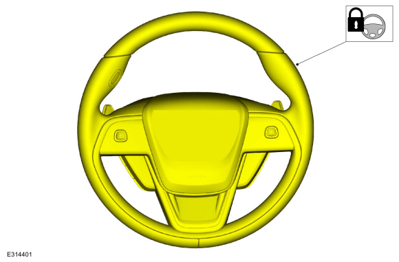
NOTICE: Do not allow the steering wheel to rotate while the steering column shaft is disconnected or damage to the clockspring may result. If there is evidence that the shaft has rotated, remove and recenter the clockspring.
Secure the steering wheel.
 |
-
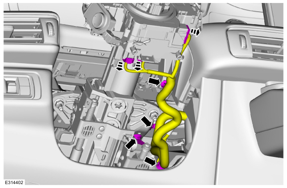
Disconnect the steering column electrical connectors and position the harness aside.
 |
-
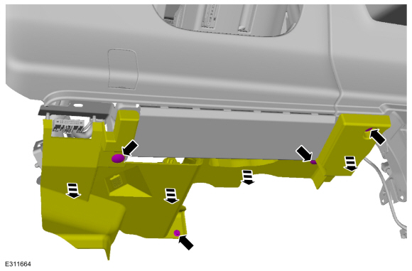
Remove the retainers and lower the driver side insulator panel
 |
-
Remove the driver side insulator panel.
-
Disconnect the electrical connector
-
Detach the pin-type retainers and position the harness aside.
-
Disconnect the electrical connector
 |
-
If equipped.
Disconnect the steering column tilt ant telescopic motor electrical connectors and position the harness aside.
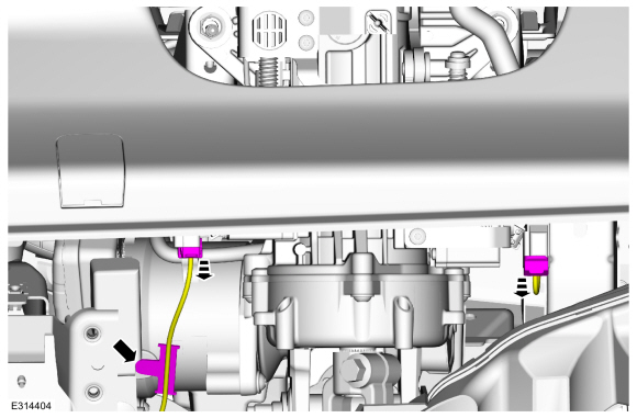 |
-
Position the front door weatherstrip aside, release that clips and remove the LH instrument panel side finish panel
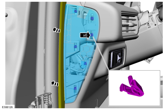 |
-
Remove the steering column opening trim panel.
-
Remove the steering column opening trim panel.
-
Disconnect the headlamp switch electrical connector.
-
Remove the steering column opening trim panel.
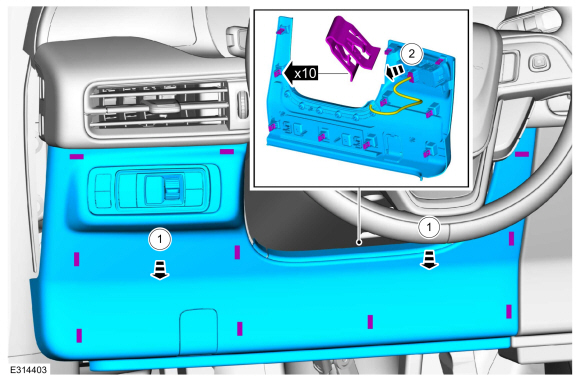 |
-
 WARNING:
Do not reuse steering column shaft bolts. This may
result in fastener failure and steering column shaft detachment or loss
of steering control. Failure to follow this instruction may result in
serious injury to vehicle occupant(s).
WARNING:
Do not reuse steering column shaft bolts. This may
result in fastener failure and steering column shaft detachment or loss
of steering control. Failure to follow this instruction may result in
serious injury to vehicle occupant(s).
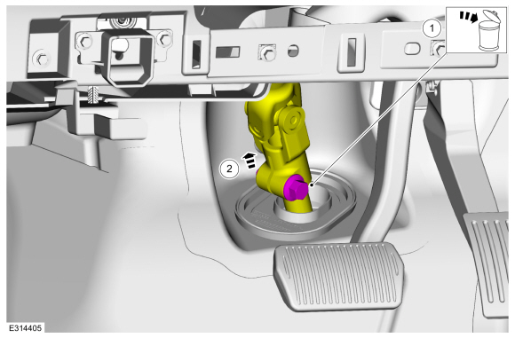
-
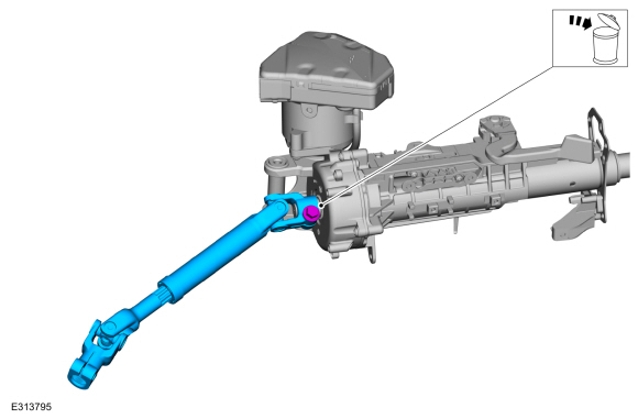
Remove and discard the steering shaft coupler retainer.
Torque: 46 lb.ft (63 Nm)
-
Separate the steering column shaft from the steering gear.
-
Remove and discard the steering shaft coupler retainer.
 |
-
Disconnect the steering column EPAS electrical connectors.
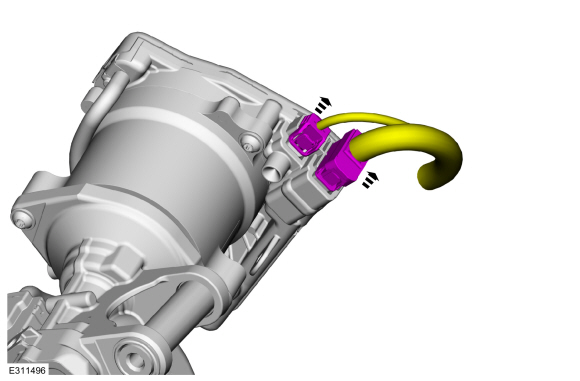 |
-
WARNING:
Do not reuse steering column nuts. This may result
in fastener failure and steering column detachment or loss of steering
control. Failure to follow this instruction may result in serious injury
to vehicle occupant(s).
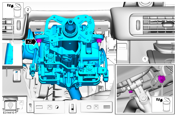
Remove the steering column.
-
Remove and discard the steering column mounting bolt.
-
Remove and discard the nuts and remove the steering column.
-
Transfer parts as required.
-
Remove and discard the steering column mounting bolt.
 |
-
WARNING:
Do not reuse steering column shaft bolts. This may
result in fastener failure and steering column shaft detachment or loss
of steering control. Failure to follow this instruction may result in
serious injury to vehicle occupant(s).
NOTE: This step is only necessary when installing a new component.
Remove and discard the steering shaft coupler retainer and remove the steering column intermediate shaft.
Torque:
Stage 1: 35 lb.ft (48 Nm)
Stage 2: 120°
 |
Installation
-
NOTE: Transfer parts as needed.
To install, reverse the removal procedure.
-
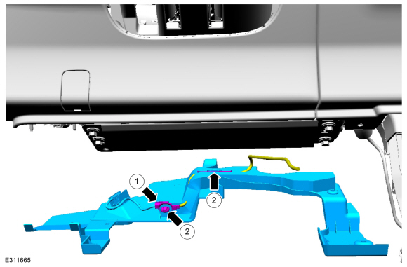
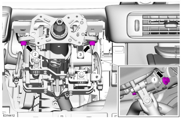
Tighten the fasteners following the sequence shown.
Torque:
1: 18 lb.ft (25 Nm)
2: 18 lb.ft (25 Nm)
3: 18 lb.ft (25 Nm)
 |
-
Repower the SRS .
Refer to: Supplemental Restraint System (SRS) Repowering (501-20B Supplemental Restraint System, General Procedures).
-
NOTE: This step is only necessary when installing a new component.
If a new steering column was installed, download the PSCM configuration from the scan tool to the new PSCM .
Refer to: Module Configuration - System Operation and Component Description (418-01 Module Configuration, Description and Operation).
-
NOTE: This step is only necessary when installing a new component.
If a new steering column was installed, using a diagnostic scan tool, carry out the ABS module configuration.
Refer to: Module Configuration - System Operation and Component Description (418-01 Module Configuration, Description and Operation).
-
To relearn steering angles, drive the vehicle above
64km/h (40 mph) for a minimum of 1 mile while maintaining the steering
wheel in a straight ahead position with minimal steering input for at
least 30 seconds.
 General Procedures - Steering Wheel Cover Repair
Materials
Name
Specification
Motorcraft® Instant Gel AdhesiveTA-19-C
WSS-M2G401-B5
Repair
NOTE:
If re-adhering leather to the front side of the
steering wheel only, it will not be necessary to remove the steering
wheel...
 Removal and Installation - Steering Column Shaft
Removal
NOTE:
Removal steps in this procedure may contain installation details.
NOTICE:
Do not allow the steering wheel to rotate while the
steering column shaft is disconnected or damage to the clockspring may
result...
Other information:
Lincoln Corsair 2020-2026 Owners Manual: Keyless Entry – Troubleshooting
Keyless Entry – Frequently Asked Questions Why does the keypad not accept the access code? If you enter the access code too fast on the keypad, the unlock function may not work. Slowly re-enter the access code. Why does the passive key not work? The system deactivates passive keys left inside your vehicle when you lock it...
Lincoln Corsair 2020-2026 Service Manual: Specifications
Lubricants, Fluids, Sealers and Adhesives-Rear electric drive assembly part number LX68-7A000-AE Specifications Material: Motorcraft® Disconnect Rear Drive Unit Fluid / XY-75W-QL Lubricants, Fluids, Sealers and Adhesives-Rear electric drive assembly part number LX68-7A000-AF or later Specifications ..
Categories
- Manuals Home
- 1st Generation Lincoln Corsair Owners Manual
- 1st Generation Lincoln Corsair Service Manual
- Auto-Start-Stop
- Auto Hold (IF EQUIPPED)
- Automatic Transmission - 8-Speed Automatic Transmission – 8F35/8F40
- New on site
- Most important about car
Information on P Type Tires
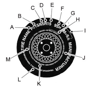
P215/65R15 95H is an example of a tire size, load index and speed rating. The definitions of these items are listed below. (Note that the tire size, load index and speed rating for your vehicle may be different from this example.)
P: Indicates a tire, designated by the Tire and Rim Association, that may be used for service on cars, sport utility vehicles, minivans and light trucks. Note: If your tire size does not begin with a letter this may mean it is designated by either the European Tire and Rim Technical Organization or the Japan Tire Manufacturing Association. 215: Indicates the nominal width of the tire in millimeters from sidewall edge to sidewall edge. In general, the larger the number, the wider the tire. 65: Indicates the aspect ratio which gives the tire's ratio of height to width. R: Indicates a radial type tire. 15: Indicates the wheel or rim diameter in inches. If you change your wheel size, you will have to purchase new tires to match the new wheel diameter. 95: Indicates the tire's load index. It is an index that relates to how much weight a tire can carry. You may find this information in your owner’s manual. If not, contact a local tire dealer.