Lincoln Corsair: Rear Suspension / Removal and Installation - Lower Arm
Special Tool(s) / General Equipment
| Vehicle/Axle Stands |
Removal
-
Remove the wheel and tire.
Refer to: Wheel and Tire (204-04A Wheels and Tires, Removal and Installation).
-
NOTICE: Take extra care when handling a compressed spring. Failure to follow this instruction may result in personal injury.
NOTICE: Make sure that the insulator pads are correctly positioned to prevent direct contact with other components.
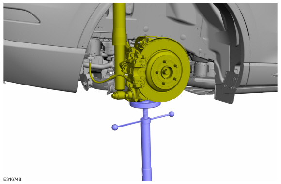
Raise the suspension approximately 20mm from rebound condition.
Use the General Equipment: Vehicle/Axle Stands
 |
-
-
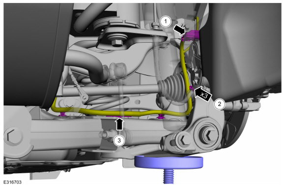
Disconnect the wheel speed sensor electrical connector.
-
Detach the wheel speed sensor wiring harness retainers.
-
Detach the wheel speed sensor wiring harness retainer.
-
Disconnect the wheel speed sensor electrical connector.
 |
-
NOTICE: The rear suspension height sensor must be disconnected from the lower control arm prior to servicing suspension components or damage to the suspension height sensor and/or the vehicle dynamic suspension system may occur. The sensor will need to be recalibrated after reassembly.
NOTE: If equipped with dynamic suspension.
-
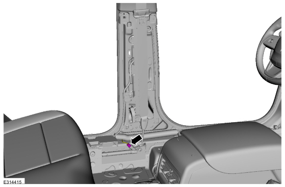
Disconnect the rear ride height sensor electrical connector.
-
Detach the rear ride height sensor wiring harness retainers.
-
Disconnect the rear ride height sensor electrical connector.
 |
-
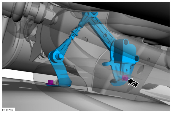
Remove the rear ride height sensor arm bracket bolts and the rear ride height sensor.
 |
-
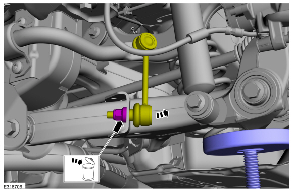
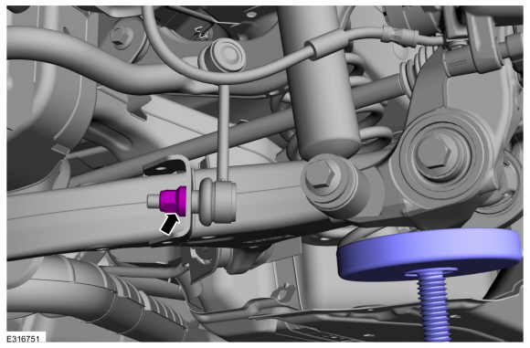
NOTICE: Do not use power tools to remove or install the stabilizer bar link nuts. Damage to the stabilizer bar link ball joints and boots may occur.
NOTE: Use the TORX PLUS® holding feature to prevent the ball stud from turning while removing or installing the lower arm outboard nut. Torx® and TORX PLUS® is a reg. tm of Acument Intellectual Properties, LLC.
The stabilizer bar links are designed with low friction ball joints that have a low breakaway torque. Remove and discard the rear stabilizer bar link lower nut and position the rear stabilizer bar link aside.
 |
-
NOTE: Make sure that the knuckle is supported with suitable retaining straps.
Remove and discard the lower arm-to-wheel knuckle bolt and nut.
 |
-
NOTICE: Take extra care when handling a compressed spring. Failure to follow this instruction may result in personal injury.
NOTICE: Make sure that the insulator pads are correctly positioned to prevent direct contact with other components.
NOTE: Make sure that the knuckle is supported with suitable retaining straps.
-
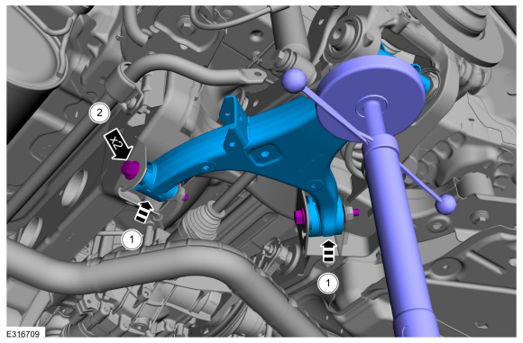
Remove and discard the rear lower arm-to-subframe bolts.
-
Remove the lower arm from subframe and knuckle.
Use the General Equipment: Vehicle/Axle Stands
-
Remove and discard the rear lower arm-to-subframe bolts.
 |
Installation
-
NOTICE: Make sure that the insulator pads are correctly positioned to prevent direct contact with other components.
-
NOTE: Make sure that the lower spring seat is properly aligned.
Position and install the lower arm to the subframe and knuckle.
-
NOTE: Make sure that the new bolts are used.
NOTE: Only tighten the bolts finger tight at this stage.
Install the new rear lower arm-to-subframe bolts.
-
 |
-
NOTE: Make sure that the knuckle is supported with suitable retaining straps.
NOTE: Make sure that the new bolt and nut is installed.
NOTE: Only tighten the nut and bolt finger tight at this stage.
Install the new lower arm-to-wheel knuckle bolt and nut.
 |
-
NOTE: Make sure that a new nut is used.
NOTE: Only tighten the nut and bolt finger tight at this stage.
Position the rear stabilizer bar link and install the new rear stabilizer bar link lower nut.
 |
-
NOTE: If equipped with dynamic suspension.
Position the rear ride height sensor and install the rear ride height sensor arm bracket bolts.
Torque: 97 lb.in (11 Nm)
|
-
NOTE: If equipped with dynamic suspension.
-
Attach the rear ride height sensor wiring harness retainers.
-
Connect the rear ride height sensor electrical connector.
-
Attach the rear ride height sensor wiring harness retainers.
 |
-
-
Attach the wheel speed sensor wiring harness retainer.
-
Attach the wheel speed sensor wiring harness retainers.
-
Connect the wheel speed sensor electrical connector.
-
Attach the wheel speed sensor wiring harness retainer.
 |
-
NOTICE: Make sure that the insulator pads are correctly positioned to prevent direct contact with other components.
Suspension at curb height.
Use the General Equipment: Vehicle/Axle Stands
 |
-
NOTICE: Tighten the suspension fasteners with the weight of the vehicle on the wheels and tires or use a suitable jack to raise the suspension to curb height or damage to the bushings may occur.
NOTE: Only tighten the nuts and bolts when the suspension is in the normal drive position.
-
Tighten the new lower arm-to-subframe bolt.
Torque:
Stage 1: 184 lb.ft (250 Nm)
Stage 2: 120°
-
Tighten the new lower arm-to-subframe bolt.
Torque:
Stage 1: 159 lb.in (18 Nm)
Stage 2: 203 lb.ft (275 Nm)
-
Tighten the new lower arm-to-subframe bolt.
 |
-
NOTICE: Tighten the suspension fasteners with the weight of the vehicle on the wheels and tires or use a suitable jack to raise the suspension to curb height or damage to the bushings may occur.
NOTE: Only tighten the nuts and bolts when the suspension is in the normal drive position.
Tighten the new lower arm-to-wheel knuckle nut.
Torque: 203 lb.ft (275 Nm)
 |
-
NOTICE: Tighten the suspension fasteners with the weight of the vehicle on the wheels and tires or use a suitable jack to raise the suspension to curb height or damage to the bushings may occur.
NOTICE: Do not use power tools to remove or install the stabilizer bar link nuts. Damage to the stabilizer bar link ball joints and boots may occur.
NOTE: Only tighten the nuts and bolts when the suspension is in the normal drive position.
NOTE: Use the TORX PLUS® holding feature to prevent the ball stud from turning while removing or installing the lower arm outboard nut. Torx® and TORX PLUS® is a reg. tm of Acument Intellectual Properties, LLC.
NOTE: The stabilizer bar links are designed with low friction ball joints that have a low breakaway torque.
Tighten the new rear stabilizer bar link lower nut.
Torque: 85 lb.ft (115 Nm)
 |
-
Install the wheel and tire.
Refer to: Wheel and Tire (204-04A Wheels and Tires, Removal and Installation).
-
Check and if necessary adjust rear camber.
Refer to: Rear Camber Adjustment (204-00 Suspension System - General Information, General Procedures).
-
Calibrate the suspension system. Connect the scan tool
and carry out the Ride Height Calibration routine. Follow the scan tool
directions.

 Removal and Installation - Rear Shock Absorber
Special Tool(s) /
General Equipment
Vehicle/Axle Stands
Removal
Remove the wheel and tire.
Refer to: Wheel and Tire (204-04A Wheels and Tires, Removal and Installation)...
Other information:
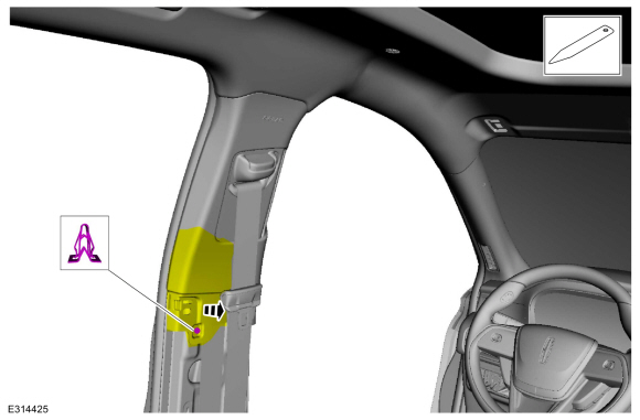
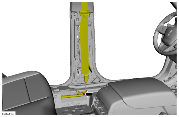
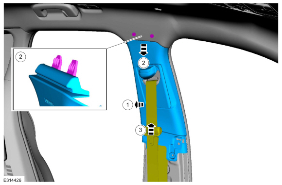
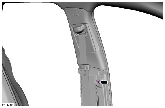
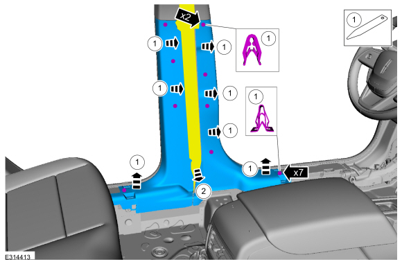
Lincoln Corsair 2020-2026 Service Manual: Removal and Installation - Front Seatbelt Retractor and Pretensioner
Removal WARNING: The following procedure prescribes critical repair steps required for correct restraint system operation during a crash. Follow all notes and steps carefully. Failure to follow step instructions may result in incorrect operation of the restraint system and increases the risk of serious personal injury or death in a crash...
Lincoln Corsair 2020-2026 Owners Manual: Vehicle Identification
Locating the Vehicle Identification Number The vehicle identification number is on the left-hand side of the instrument panel. Note: In the illustration, XXXX is representative of your vehicle identification number. Vehicle Identification Number Overview The vehicle identification number contains the following information: World manufacturer identifier...
Categories
- Manuals Home
- 1st Generation Lincoln Corsair Owners Manual
- 1st Generation Lincoln Corsair Service Manual
- Exterior Mirrors
- Warning Lamps and Indicators
- Capacities and Specifications - 2.0L
- New on site
- Most important about car
Keyless Starting
Note: The keyless starting system may not function if the key is close to metal objects or electronic devices such as cellular phones.
Note: A valid key must be located inside your vehicle to switch the ignition on and start the engine.
Ignition Modes