Lincoln Corsair: Evaporative Emissions - 2.0L EcoBoost (177kW/240PS) – MI4 / Removal and Installation - Evaporative Emission Canister
Removal
 WARNING:
Do not smoke, carry lighted tobacco or have an open flame of
any type when working on or near any fuel-related component. Highly
flammable mixtures may be present and may be ignited. Failure to follow
these instructions may result in serious personal injury.
WARNING:
Do not smoke, carry lighted tobacco or have an open flame of
any type when working on or near any fuel-related component. Highly
flammable mixtures may be present and may be ignited. Failure to follow
these instructions may result in serious personal injury.
WARNING:
Do not carry personal electronic devices such as cell
phones, pagers or audio equipment of any type when working on or near
any fuel-related component. Highly flammable mixtures may be present and
may be ignited. Failure to follow these instructions may result in
serious personal injury.
WARNING:
Always disconnect the battery ground cable at the battery
when working on an evaporative emission (EVAP) system or fuel-related
component. Highly flammable mixtures may be present and may be ignited.
Failure to follow these instructions may result in serious personal
injury.
NOTE: Removal steps in this procedure may contain installation details.
-
With the vehicle in NEUTRAL, position it on a hoist.
Refer to: Jacking and Lifting (100-02 Jacking and Lifting - 2.0L EcoBoost (177kW/240PS) - MI4) .
-
Disconnect the negative battery cable.
Refer to: Battery Disconnect and Connect (414-01 Battery, Mounting and Cables - 2.0L EcoBoost (177kW/240PS) - MI4) .
-
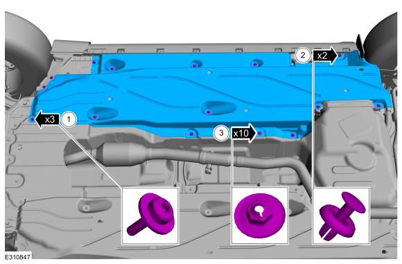
Remove the fasteners and the LH deflector shield.
 |
-
-
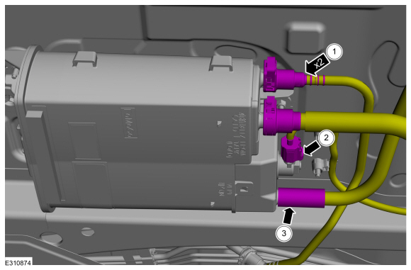
Disconnect the EVAP canister quick release couplings.
Refer to: Quick Release Coupling (310-00 Fuel System - General Information - 2.0L EcoBoost (177kW/240PS) - MI4) .
-
Disconnect the EVAP canister electrical connector.
-
Disconnect the vent hose.
-
Disconnect the EVAP canister quick release couplings.
 |
-
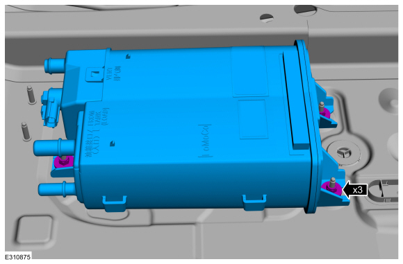
Remove the nuts and the EVAP canister.
Torque: 27 lb.in (3 Nm)
 |
Installation
-
To install, reverse the removal procedure.
 Removal and Installation - Evaporative Emission Blocking Valve
Removal
NOTE:
The evaporative emission blocking valve is serviced with the fuel tank pressure sensor and tube.
Refer to: Fuel Tank Pressure Sensor and Tube (303-13A Evaporative
Emissions - 2...
 Removal and Installation - Evaporative Emission Canister Purge Valve
Materials
Name
Specification
Motorcraft® Silicone Brake Caliper Grease and Dielectric CompoundXG-3-A
ESA-M1C200-AESE-M1C171-A
Removal
WARNING:
Do not smoke, carry lighted tobacco or have an open flame of
any type when working on or near any fuel-related component...
Other information:
Lincoln Corsair 2020-2026 Service Manual: Disassembly and Assembly - Wheel and Tire
Special Tool(s) / General Equipment Wooden Block DISASSEMBLY NOTICE: Failure to follow the instructions below may result in damage to the TPMS . NOTICE: The TPMS sensor is mounted to the valve stem. Removal of the valve stem requires dismounting the tire from the wheel and removal of the TPMS sensor...
Lincoln Corsair 2020-2026 Service Manual: Description and Operation - Body - Overview
Insulation Insulation is used as a sound-deadener to reduce exterior road and powertrain noises from the interior of the vehicle. Mastic insulators are also used as insulation. Insulation is installed: under the roof. above and below the instrument panel...
Categories
- Manuals Home
- 1st Generation Lincoln Corsair Owners Manual
- 1st Generation Lincoln Corsair Service Manual
- Exterior Mirrors
- Programming the Garage Door Opener to Your Hand-Held Transmitter
- Head Up Display
- New on site
- Most important about car
Autowipers (IF EQUIPPED)
Wet or winter driving conditions with ice, snow or salty road mist can cause inconsistent and unexpected wiping or smearing.