Lincoln Corsair: Engine Emission Control - 2.0L EcoBoost (177kW/240PS) – MI4 / Removal and Installation - Crankcase Ventilation Tube
Special Tool(s) / General Equipment
| Side Cutter Pliers |
Materials
| Name | Specification |
|---|---|
| Motorcraft® Silicone Brake Caliper Grease and Dielectric Compound XG-3-A |
ESA-M1C200-A ESE-M1C171-A |
Removal
-
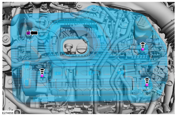
NOTE: Do not pull the engine appearance cover forward or sideways to remove. Failure to press straight upward on the underside of the cover at the attachment points may result in damage to the cover or engine components.
-
Remove the engine appearance cover nut.
-
Place your hand under the engine appearance cover at
each grommet location and push straight up to release each grommet from
the studs.
-
After all of the grommets have been released from the studs, remove the appearance cover from the engine.
-
Remove the engine appearance cover nut.
 |
-
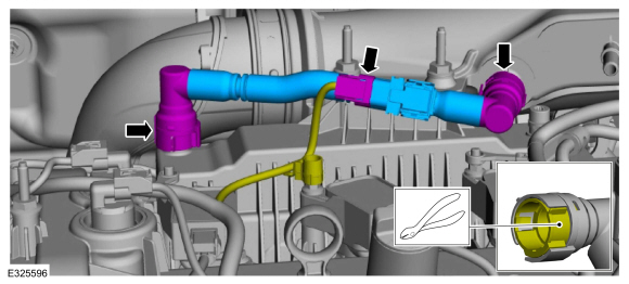
NOTE: The crankcase vent tube may have either a permanent or quick connect connector at one or both ends. If the tube needs to be removed for any reason, the permanent connector(s) must be cut to remove the tube. The tube will then need to be replaced.
NOTE: If the crankcase vent tube is replaced, the replacement part may not come with a crankcase pressure sensor. If so, the PCM will need to be reprogrammed.
-
If equipped, disconnect the wiring harness electrical connector.
-
If necessary, cut the lock tab.
Use the General Equipment: Side Cutter Pliers
-
If either crankcase vent tube connector was cut, remove and discard the crankcase vent tube.
-
If equipped, disconnect the wiring harness electrical connector.
 |
Installation
-
-
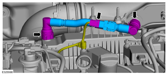
Install the new crankcase vent tube.
-
If the replacement crankcase vent tube part comes with no crankcase pressure sensor, reprogram the PCM .
Refer to: Module Programming (418-01 Module Configuration, General Procedures).
-
If the replacement crankcase vent tube came without a
crankcase pressure sensor, tape the wiring harness electrical connector
back to the wiring harness.
-
If the replacement crankcase vent tube comes with a
crankcase pressure sensor, connect the wiring harness electrical
connector.
-
Install the new crankcase vent tube.
 |
-
-
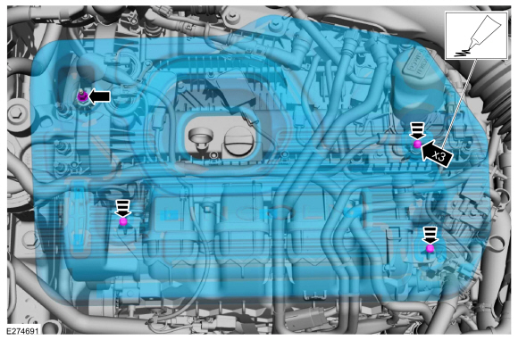
NOTE: Lubricating the grommets with silicone grease aids in the installation of the engine appearance cover, and any future removal and installation of the cover.
Lubricate each grommet with silicone grease.
Material: Motorcraft® Silicone Brake Caliper Grease and Dielectric Compound / XG-3-A (ESA-M1C200-A) (ESE-M1C171-A)
-
If the engine appearance cover stud bolt is loosened
or removed, it must be installed/tightened into the valve cover.
Torque: 62 lb.in (7 Nm)
-
Position the engine appearance cover onto the engine with the grommets aligned with the studs.
-
Press down on the engine appearance cover at each grommet location to attach the grommets onto the studs.
-
Install the engine appearance cover nut.
Torque: 44 lb.in (5 Nm)
-
 |
 Diagnosis and Testing - Exhaust Gas Recirculation (EGR) System
Diagnostic Trouble Code (DTC) Chart
Diagnostics in this manual assume a certain skill level and knowledge of Ford-specific diagnostic practices.REFER to: Diagnostic Methods (100-00 General Information, Description and Operation)...
 Removal and Installation - Crankcase Vent Oil Separator
Removal
NOTE:
Removal steps in this procedure may contain installation details.
Remove the intake manifold.
Refer to: Intake Manifold (303-01A Engine - 2...
Other information:
Lincoln Corsair 2020-2026 Owners Manual: Capacities and Specifications - 2.3L
Use oil and fluid that meets the defined specification and viscosity grade. If you do not use oil and fluid that meets the defined specification and viscosity grade, it could result in: Component damage that your vehicle warranty does not cover...
Lincoln Corsair 2020-2026 Service Manual: Removal and Installation - Intermediate Shaft
Special Tool(s) / General Equipment 100-001 (T50T-100-A) Slide Hammer 205-1076Link Shaft tool E-Drive Rear Axle 205-153 (T80T-4000-W) Handle 303-D1665 (303-DS005) Puller, Blind Hole Removal Remove the rear halfshaft LH ...
Categories
- Manuals Home
- 1st Generation Lincoln Corsair Owners Manual
- 1st Generation Lincoln Corsair Service Manual
- Programming the Garage Door Opener to Your Garage Door Opener Motor
- Auto Hold (IF EQUIPPED)
- Memory Function
- New on site
- Most important about car
USB Port
WARNING: Driving while distracted can result in loss of vehicle control, crash and injury. We strongly recommend that you use extreme caution when using any device that may take your focus off the road. Your primary responsibility is the safe operation of your vehicle. We recommend against the use of any hand-held device while driving and encourage the use of voice-operated systems when possible. Make sure you are aware of all applicable local laws that may affect the use of electronic devices while driving.
USB A
