Lincoln Corsair: Rear Seats / Removal and Installation - Rear Head Restraint Guide Sleeve
Lincoln Corsair 2020-2024 Service Manual / Body and Paint / Body and Paint / Rear Seats / Removal and Installation - Rear Head Restraint Guide Sleeve
Special Tool(s) / General Equipment
| Flat Headed Screw Driver |
Removal
Outboard head restraint guide sleeves
-
-
Push the rear seat outboard head restraint release buttons.
-
Remove the rear seat outboard head restraint.
-
Push the rear seat outboard head restraint release buttons.
.jpg) |
-
-
Push down on the rear seat backrest cover to
gain access to the outboard head restraint guide sleeve retaining clip.
-
Remove and discard the outboard head restraint guide sleeve retaining clip.
-
Push down on the rear seat backrest cover to
gain access to the outboard head restraint guide sleeve retaining clip.
.jpg) |
Center head restraint guide sleeves
-
-
Push the rear seat center head restraint release button.
-
Remove the rear seat center head restraint.
-
Push the rear seat center head restraint release button.
.jpg) |
All head restraint guide sleeves
-
NOTE: Follow the unique instructions or graphics for this step in the installation.
Using a flat head screwdriver, release the head restraint guide sleeve locking tab. Remove the head restraint guide sleeve and discard.
Use the General Equipment: Flat Headed Screw Driver
.jpg) |
Installation
-
NOTICE: Always install new head restraint guide sleeves. Difficult adjustment of the head restraint may occur. Failure to follow these instructions may result in component failure.
NOTICE: The head restraint guide sleeves are not interchangeable. Failure to install the correct head restraint guide sleeve at the correct position may result in component failure.
To install, reverse the removal procedure.
-
Allow the head restraint guide sleeve to slide freely
through the backrest foam and backrest trim cover. Using hand pressure,
twist the head restraint guide sleeve while pushing it into the backrest
frame until the tab is locked into place.
.jpg) |
 Removal and Installation - Power Fold Seat Motor
Removal
NOTE:
Removal steps in this procedure may contain installation details.
Remove the rear seat cushion and cover as an assembly.
Refer to: Rear Seat Cushion Cover (501-10B Rear Seats, Removal and Installation)...
 Removal and Installation - Rear Seat
Special Tool(s) /
General Equipment
Interior Trim Remover
Removal
WARNING:
The following procedure describes critical repair steps
required for correct seat component installation...
Other information:
Lincoln Corsair 2020-2024 Service Manual: Removal and Installation - Roof Reinforcement
Special Tool(s) / General Equipment Resistance Spotwelding Equipment Spot Weld Drill Bit Locking Pliers Removal WARNING: Electric vehicles damaged by a crash may have compromised high voltage safety systems and present a potential high voltage electrical shock hazard...
Lincoln Corsair 2020-2024 Service Manual: Removal and Installation - Inner Quarter Panel
Special Tool(s) / General Equipment Resistance Spotwelding Equipment Scraper for Straight Edges Hot Air Gun 8 mm Drill Bit MIG/MAG Welding Equipment Spot Weld Drill Bit Locking Pliers Materials Name Specification Flexible Foam Repair3M™ 08463, LORD Fusor® 121 - Removal WARNING: Electric vehicles damaged by a crash may ha..
Categories
- Manuals Home
- 1st Generation Lincoln Corsair Owners Manual
- 1st Generation Lincoln Corsair Service Manual
- Keyless Entry Settings
- Programming the Garage Door Opener to Your Garage Door Opener Motor
- Remote Start Settings
- New on site
- Most important about car
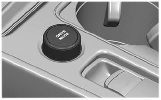
Selecting a Drive Mode. DRIVE MODES
Selecting a Drive Mode
Note: Drive mode changes may not be available when the ignition is off.
Copyright © 2024 www.licorsair.com