Lincoln Corsair: Intake Air Distribution and Filtering - 2.0L EcoBoost (177kW/240PS) – MI4 / Removal and Installation - Charge Air Cooler (CAC) Intake Pipe
Special Tool(s) / General Equipment
| Hose Clamp Remover/Installer |
Removal
NOTICE: During engine repair procedures, cleanliness is extremely important. All parts must be thoroughly cleaned and any foreign material, including any material created while cleaning gasket surfaces, that enters the oil passages, coolant passages or the oil pan, can cause engine failure.
NOTICE: The turbocharger compressor vanes can be damaged by even the smallest particles. When removing any turbocharger or engine air intake system component, ensure that no debris enters the system. Failure to do so may result in damage to the turbocharger.
NOTE: Removal steps in this procedure may contain installation details.
-
Refer to: Health and Safety Precautions (100-00 General Information, Description and Operation).
-
Remove the air cleaner.
Refer to: Air Cleaner (303-12A Intake Air Distribution and Filtering - 2.0L EcoBoost (177kW/240PS) – MI4, Removal and Installation).
-
Remove the air cleaner outlet pipe.
Refer to: Air Cleaner Outlet Pipe (303-12A Intake Air Distribution and Filtering - 2.0L EcoBoost (177kW/240PS) – MI4, Removal and Installation).
-
Remove the battery tray.
Refer to: Battery Tray - 2.0L EcoBoost (177kW/240PS) – MI4/2.3L EcoBoost (199kW/270PS) (414-01 Battery, Mounting and Cables, Removal and Installation).
-
With the vehicle in NEUTRAL, position it on a hoist.
Refer to: Jacking and Lifting - Overview (100-02 Jacking and Lifting, Description and Operation).
-
Drain the cooling system.
Refer to: Engine Cooling System Draining, Vacuum Filling and Bleeding (303-03A Engine Cooling - 2.0L EcoBoost (177kW/240PS) – MI4, General Procedures).
-
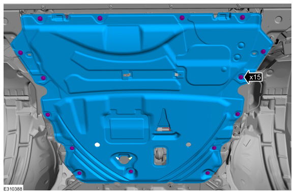
Remove the bolts and remove the undershield.
Torque: 13 lb.in (1.5 Nm)
 |
-
-
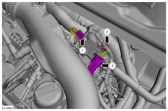
Detach the wiring clip.
-
Disconnect the HO2S connector.
-
Disconnect the CAC tube bypass valve electrical connector and wire retainer.
-
Detach the wiring clip.
 |
-
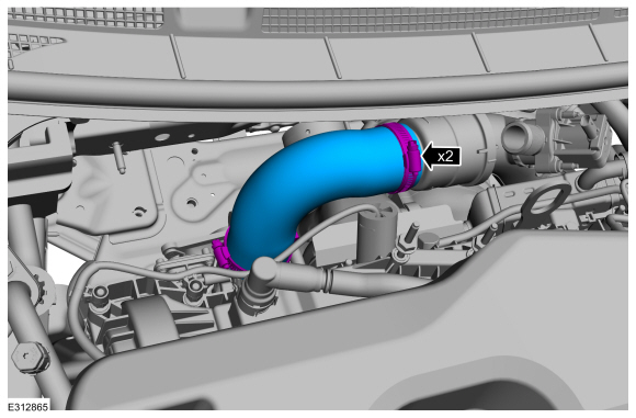
Loosen the clamps and remove the CAC tube.
Torque: 48 lb.in (5.4 Nm)
 |
-
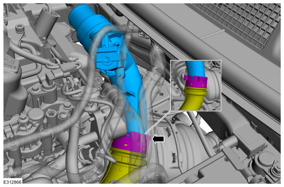
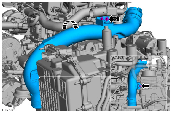
NOTE: Ensure the quick fit connector is fully inserted until the wire clip falls into the groove and gets locked.
Detach quick fit connector and remove the middle CAC intake pipe.
 |
-
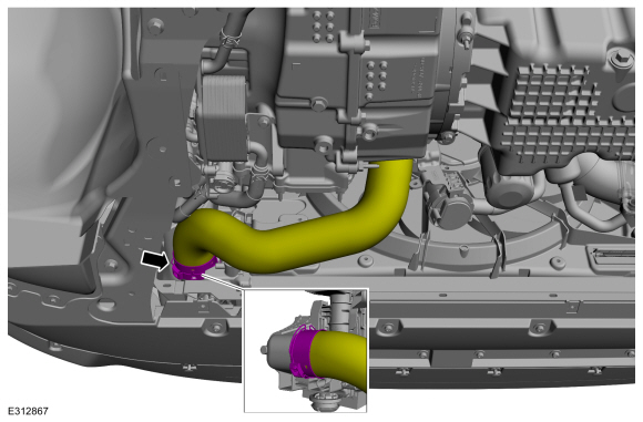
Release the clip LH front CAC tube aside.
 |
-
-
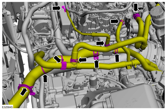
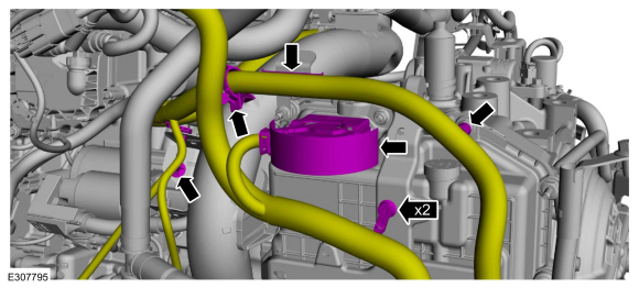
Detach the coolant hose retainers.
-
Disconnect heater hose from the EGR cooler.
-
Release the clamp, retainer and position the aside degas bottle coolant hose.
Use the General Equipment: Hose Clamp Remover/Installer
-
Release the clamps and disconnect the coolant hoses and position aside.
Use the General Equipment: Hose Clamp Remover/Installer
-
Detach the coolant hose retainers.
 |
-
-
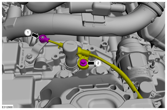
Disconnect the manual park release cable from the manual control lever.
-
Remove the bolt and position the manual park release cable aside.
Torque: 177 lb.in (20 Nm)
-
Disconnect the manual park release cable from the manual control lever.
 |
-
Remove the nut and the manual control lever.
Torque: 106 lb.in (12 Nm)
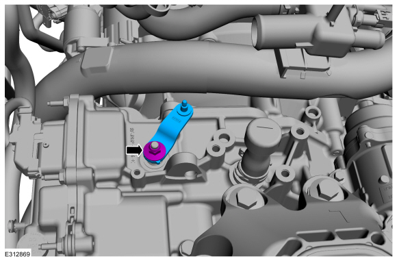 |
-
Disconnect the transmission wiring harness connector and detach the retainers.
 |
-
-
Remove the nut.
Torque: 106 lb.in (12 Nm)
-
Remove the bolts and remove the CAC intake pipe.
Torque: 48 lb.in (5.4 Nm)
-
Remove the nut.
 |
Installation
-
Inspect the turbocharger or engine air intake system components and clean, if necessary.
-
To install, reverse the removal procedure.
 Removal and Installation - Charge Air Cooler (CAC)
Removal
Refer to: Radiator (303-03B Engine Cooling - 2.3L EcoBoost (199kW/270PS), Removal and Installation).
Installation
Refer to: Radiator (303-03B Engine Cooling - 2...
 Removal and Installation - Charge Air Cooler (CAC) Outlet Pipe
Removal
NOTICE:
The turbocharger compressor vanes can be damaged by even the
smallest particles. When removing any turbocharger or engine air intake
system component, ensure that no debris enters the system...
Other information:
Lincoln Corsair 2020-2024 Service Manual: Removal and Installation - Evaporative Emission Canister Vent Solenoid
Removal WARNING: Do not smoke, carry lighted tobacco or have an open flame of any type when working on or near any fuel-related component. Highly flammable mixtures may be present and may be ignited. Failure to follow these instructions may result in serious personal injury...
Lincoln Corsair 2020-2024 Service Manual: Removal and Installation - Front Brake Flexible Hose
Removal WARNING: Service actions on vehicles equipped with electronic brake booster and electronic parking brakes may cause unexpected brake application, which could result in injury to hands or fingers. Put the brake system into service mode prior to servicing or removing any brake components...
Categories
- Manuals Home
- 1st Generation Lincoln Corsair Owners Manual
- 1st Generation Lincoln Corsair Service Manual
- Auto Hold (IF EQUIPPED)
- Refueling - Gasoline
- Automatic Transmission - 8-Speed Automatic Transmission – 8F35/8F40
- New on site
- Most important about car
USB Port
WARNING: Driving while distracted can result in loss of vehicle control, crash and injury. We strongly recommend that you use extreme caution when using any device that may take your focus off the road. Your primary responsibility is the safe operation of your vehicle. We recommend against the use of any hand-held device while driving and encourage the use of voice-operated systems when possible. Make sure you are aware of all applicable local laws that may affect the use of electronic devices while driving.
USB A