Lincoln Corsair: Rear Drive Axle/Differential / Removal and Installation - Axle Assembly
Special Tool(s) / General Equipment
| Transmission Jack | |
| Wooden Block |
Removal
NOTE: Removal steps in this procedure may contain installation instructions.
-
Remove the rear halfshafts.
Refer to: Rear Halfshaft (205-05 Rear Drive Halfshafts, Removal and Installation).
-
Remove the fuel tank.
Refer to: Fuel Tank (310-01A Fuel Tank and Lines - 2.0L EcoBoost (177kW/240PS) – MI4, Removal and Installation).
Refer to: Fuel Tank (310-01B Fuel Tank and Lines - 2.3L EcoBoost (199kW/270PS), Removal and Installation).
-
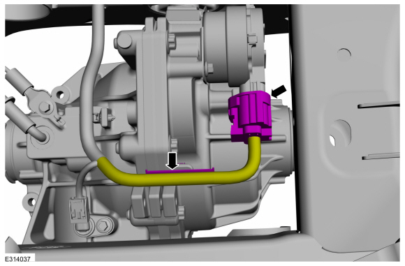
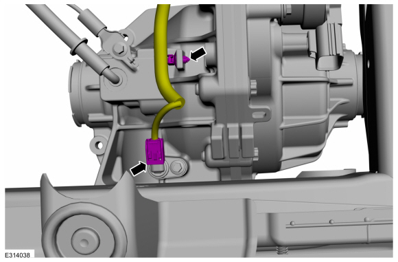
Disconnect the RDU actuator motor electrical connector and detach wiring harness retainer.
 |
-
Disconnect the RDU speed sensor electrical connector and detach wiring harness retainer.
 |
-
-
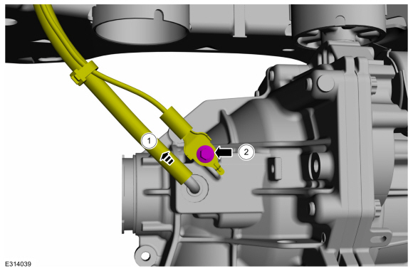
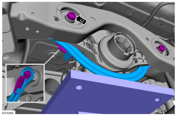
Remove the rear differential vent hose from RDU and position aside.
-
Remove the bolt and position the ground cable aside.
Torque: 106 lb.in (12 Nm)
-
Remove the rear differential vent hose from RDU and position aside.
 |
-
Position a transmission jack and wooden block to secure the RDU .
Use the General Equipment: Transmission Jack
Use the General Equipment: Wooden Block
 |
-
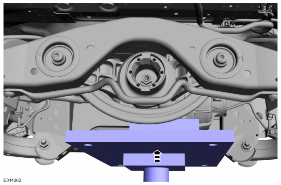
Remove the front RDU mounting bolts, nut and the protection shield.
Use the General Equipment: Transmission Jack
Use the General Equipment: Wooden Block
Torque: 76 lb.ft (103 Nm)
 |
-
Remove the rear RDU mounting bolts.
Torque: 76 lb.ft (103 Nm)
 |
-
Lower the transmission jack and remove the rear axle assembly.
Use the General Equipment: Transmission Jack
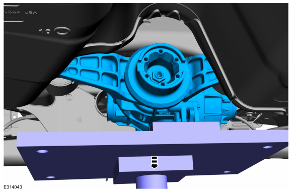 |
Installation
-
To install, reverse the removal procedure.
-
Check the differential fluid level.
Refer to: Differential Fluid Level Check (205-02 Rear Drive Axle/Differential, General Procedures).
-
NOTICE: If replacing the axle assembly, the AWD control module will need to be reconfigured with the new RDU bar code information. If the new bar code information does not match the existing AWD control module information, driveline damage or driveability concerns can occur.
NOTE: Using the diagnostic scan tool, carry out the rear drive unit calibration routine.
NOTE: The 16/17 -digit alpha numeric bar code is located on the label attached to the RDU . Using the scan tool, configure RDU bar code to AWD module through the OBD port.
 General Procedures - Differential Fluid Level Check
Check
With the vehicle in NEUTRAL, position it on a hoist.
Refer to: Jacking and Lifting - Overview (100-02 Jacking and Lifting, Description and Operation)...
 Removal and Installation - Drive Pinion Flange
Special Tool(s) /
General Equipment
205-126
(T78P-4851-A)
Holding Fixture, Drive Pinion Flange
205-233
(T85T-4851-AH)
Installer, Drive Pinion FlangeTKIT-1985-FH-1
303-249Remover, Crankshaft Timing Pulley
Flat-Bladed Screwdriver
Materials
Name
Specification
Motorcraft® Premium Long-Life GreaseXG-1-E1
ESA-M1C75-B
Removal
Remov..
Other information:
Lincoln Corsair 2020-2026 Service Manual: Removal and Installation - Air Cleaner
Removal NOTICE: The turbocharger compressor vanes can be damaged by even the smallest particles. When removing any turbocharger or engine air intake system component, ensure that no debris enters the system. Failure to do so may result in damage to the turbocharger. NOTE: Removal steps in this procedure may contain installation details. Dislodge and relocate the air cleane..
Lincoln Corsair 2020-2026 Service Manual: Removal and Installation - Crankcase Vent Oil Separator
Removal NOTE: Removal steps in this procedure may contain installation details. Remove the intake manifold. Refer to: Intake Manifold (303-01A Engine - 2.0L EcoBoost (177kW/240PS) – MI4, Removal and Installation). Remove the crankcase vent oil separator bolts and then remove the crankcase vent oil separator. Inspect the crankcase v..
Categories
- Manuals Home
- 1st Generation Lincoln Corsair Owners Manual
- 1st Generation Lincoln Corsair Service Manual
- Normal Scheduled Maintenance
- Refueling - Gasoline
- Overhaul - Main Control Valve Body
- New on site
- Most important about car
360 Degree Camera Cameras
Locating the Rear View Camera

The rear view camera is on the tailgate.
Locating the Front View Camera