Lincoln Corsair: Rear Drive Axle/Differential / Removal and Installation - Drive Pinion Flange
Special Tool(s) / General Equipment
 |
205-126
(T78P-4851-A)
Holding Fixture, Drive Pinion Flange |
 |
205-233
(T85T-4851-AH)
Installer, Drive Pinion Flange TKIT-1985-FH-1 |
 |
303-249 Remover, Crankshaft Timing Pulley |
| Flat-Bladed Screwdriver | |
Materials
| Name | Specification |
|---|---|
| Motorcraft® Premium Long-Life Grease XG-1-E1 |
ESA-M1C75-B |
Removal
-
Remove the muffler and tail pipe.
Refer to: Muffler and Tailpipe (309-00A Exhaust System - 2.0L EcoBoost (177kW/240PS) – MI4, Removal and Installation).
Refer to: Muffler and Tailpipe (309-00B Exhaust System - 2.3L EcoBoost (199kW/270PS), Removal and Installation).
-
-
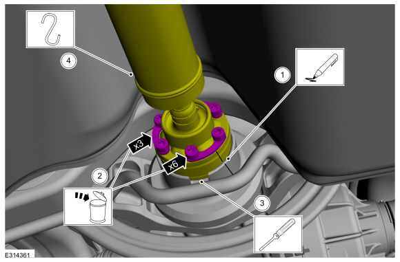
Index mark the driveshaft and the RDU flange for reference during installation.
-
Remove and discard the driveshaft to RDU pinion flange bolts and retaining straps.
-
NOTE: Do not remove driveshaft from the pinion flange by pulling on the driveshaft tube. Damage to the CV joint can result.
NOTE: The driveshaft to drive pinion flange is a tight fit and will not come apart until the center bearing is lowered.
Using a general equipment, separate the driveshaft from the drive pinion flange.
Use the General Equipment: Flat-Bladed Screwdriver
-
Position aside and support the rear driveshaft.
-
Index mark the driveshaft and the RDU flange for reference during installation.
 |
-
NOTE: Do not allow the driveshaft to hang. Secure the driveshaft so the CV-joint does not over articulate.
Separate the driveshaft from the drive pinion flange.
-
Remove the rear center bearing nuts.
-
Position the driveshaft aside.
-
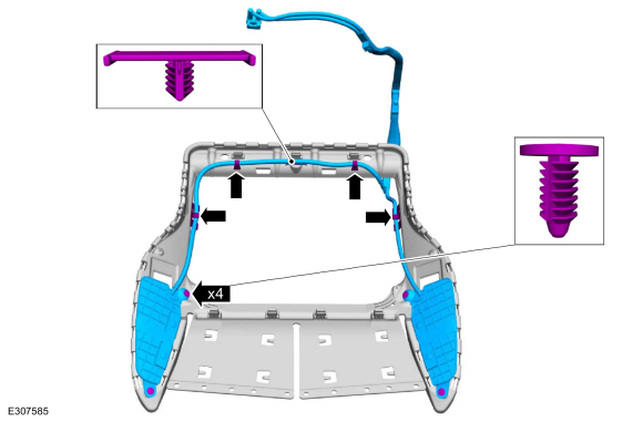
Remove the rear center bearing nuts.
 |
-
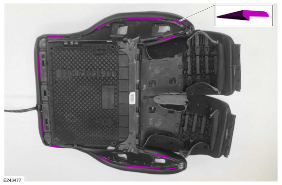
Remove the bolts and the stabilizer bar.
 |
-
NOTE: Rotational torque of the drive pinion flange must be measured and recorded using a Nm (lb-in) torque wrench for correct pinion bearing preload when reassembled. This will be the torque-to-turn measurement.
Using a dial type torque wrench, measure and record the rotational torque of the drive pinion.
 |
-
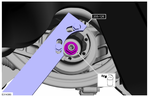
Using the special tool to hold the drive pinion flange, remove and discard the drive pinion nut.
Install Special Service Tool: 205-126 (T78P-4851-A) Holding Fixture, Drive Pinion Flange.
 |
-
Index-mark the drive pinion flange and the drive pinion stem for reassembly.
 |
-
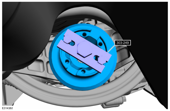
Using a special tool, remove the drive pinion flange.
Use Special Service Tool: 303-249 Remover, Crankshaft Timing Pulley.
 |
Installation
-
If necessary.
Install a new drive pinion seal.
Refer to: Drive Pinion Seal (205-02 Rear Drive Axle/Differential, Removal and Installation).
-
Lubricate the drive pinion flange mating surfaces with grease.
Material: Motorcraft® Premium Long-Life Grease / XG-1-E1 (ESA-M1C75-B)
 |
-
NOTE: Make sure drive pinion flange and drive pinion stem are phased correctly using previously applied mark.
Align the index-mark and using the special tool, install the drive pinion flange.
Use Special Service Tool: 205-233 (T85T-4851-AH) Installer, Drive Pinion Flange.
 |
-
NOTICE: Under no circumstances is the pinion nut to be backed off to reduce drive pinion bearing preload. If reduced drive pinion bearing preload is required, a new drive pinion collapsible spacer and pinion nut must be installed or damage to the component may occur.
NOTE: Refer to the rotational torque previously recorded with the Nm (lb-in) torque wrench. Tighten the pinion nut in small increments until it is within 0.3 Nm (3 lb-in) of the reference measurement. If 0.3 Nm (3 lb-in) is exceeded, then the collapsible spacer will be damaged and a new rear drive axle will be required.
Using the special tool, install the RDU pinion nut.
Install Special Service Tool: 205-126 (T78P-4851-A) Holding Fixture, Drive Pinion Flange.
 |
-
Install the stabilizer bar and the bolts.
Torque: 35 lb.ft (48 Nm)
|
-
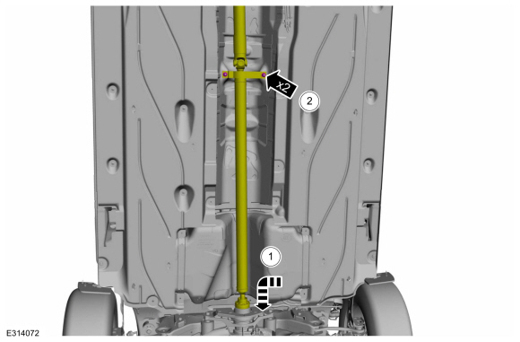
Install the driveshaft to the drive pinion flange.
-
Position the driveshaft CV flange into the drive pinion flange.
-
Install the rear center bearing nuts.
Torque: 41 lb.ft (55 Nm)
-
Position the driveshaft CV flange into the drive pinion flange.
 |
-
-
NOTE: Make sure that the component is installed to the position noted before removal.
Align the index-mark on the driveshaft to the RDU flange.
-
Install the new driveshaft to RDU pinion flange bolts and retaining straps.
Torque: 26 lb.ft (35 Nm)
-
 |
-
Install the muffler and tail pipe.
Refer to: Muffler and Tailpipe (309-00A Exhaust System - 2.0L EcoBoost (177kW/240PS) – MI4, Removal and Installation).
Refer to: Muffler and Tailpipe (309-00B Exhaust System - 2.3L EcoBoost (199kW/270PS), Removal and Installation).
-
Check the RDU fluid level.
Refer to: Differential Fluid Level Check (205-02 Rear Drive Axle/Differential, General Procedures).
 Removal and Installation - Axle Assembly
Special Tool(s) /
General Equipment
Transmission Jack
Wooden Block
Removal
NOTE:
Removal steps in this procedure may contain installation instructions...
 Removal and Installation - Drive Pinion Seal
Special Tool(s) /
General Equipment
205-208
(T83T-4676-A)
Installer, Drive Pinion Oil SealTKIT-1983-FTKIT-1983-FLMTKIT-1983-FX
Flat Headed Screw Driver
Materials
Name
Specification
Motorcraft® Premium Long-Life GreaseXG-1-E1
ESA-M1C75-B
Removal
Remove the drive pinion flange...
Other information:
Lincoln Corsair 2020-2026 Owners Manual: Creating a Vehicle Wi-Fi Hotspot
You can create a Wi-Fi hotspot in your vehicle and allow devices to connect to it for access to the Internet. Select the settings option on the feature bar. Press Lincoln Connect. Press Vehicle Hotspot.Note: The vehicle hotspot default setting is on...
Lincoln Corsair 2020-2026 Service Manual: Description and Operation - Final Drive
Final Drive Component Exploded View Item Description 1 Park gear 2 Drive chain 3 Drive chain drive sprocket 4 Drive chain driven sprocket 5 Final drive planetary sun gear 6 Differential assembly 7 Final drive planetary ring gear 8 Torque convert..
Categories
- Manuals Home
- 1st Generation Lincoln Corsair Owners Manual
- 1st Generation Lincoln Corsair Service Manual
- Technical Specifications
- Fuel Quality - Gasoline
- Refueling - Gasoline
- New on site
- Most important about car
Keyless Starting
Note: The keyless starting system may not function if the key is close to metal objects or electronic devices such as cellular phones.
Note: A valid key must be located inside your vehicle to switch the ignition on and start the engine.
Ignition Modes