Lincoln Corsair Manuals

Lincoln Corsair: Rear Electric Drive Assembly / Diagnosis and Testing - Rear Electric Drive Assembly

Lincoln Corsair 2020-2024 Service Manual / Powertrain / Frame and Mounting / Rear Electric Drive Assembly / Diagnosis and Testing - Rear Electric Drive Assembly

Diagnostic Trouble Code (DTC) Chart

Diagnostics in this manual assume a certain skill level and knowledge of Ford-specific diagnostic practices.
REFER to: Diagnostic Methods (100-00 General Information, Description and Operation).


Module DTC Description Action
APIM U0136:00 Lost Communication With Differential Control Module - Rear: No Sub Type Information GO to Pinpoint Test BE
BCM U0136:00 Lost Communication With Differential Control Module - Rear: No Sub Type Information GO to Pinpoint Test BE
BCMC U0136:00 Lost Communication With Differential Control Module - Rear: No Sub Type Information GO to Pinpoint Test BE
BECM U0136:00 Lost Communication With Differential Control Module - Rear: No Sub Type Information GO to Pinpoint Test BE
DCDC U0136:00 Lost Communication With Differential Control Module - Rear: No Sub Type Information GO to Pinpoint Test BE
IPC U0136:00 Lost Communication With Differential Control Module - Rear: No Sub Type Information GO to Pinpoint Test BE
PAM U0136:00 Lost Communication With Differential Control Module - Rear: No Sub Type Information GO to Pinpoint Test BE
PCM U0136:00 Lost Communication With Differential Control Module - Rear: No Sub Type Information GO to Pinpoint Test BE
SOBDMB P0560:00 System Voltage: No Sub Type Information GO to Pinpoint Test A
SOBDMB P0562:00 System Voltage Low: No Sub Type Information GO to Pinpoint Test B
SOBDMB P0563:00 System Voltage High: No Sub Type Information GO to Pinpoint Test C
SOBDMB P0600:49 Serial Communication Link: Internal Electronic Failure GO to Pinpoint Test D
SOBDMB P0600:88 Serial Communication Link: Bus Off GO to Pinpoint Test D
SOBDMB P060A:44 Internal Control Module Monitoring Processor Performance: Data Memory Failure GO to Pinpoint Test F
SOBDMB P060A:47 Internal Control Module Monitoring Processor Performance: Watchdog/Safety µC Failure GO to Pinpoint Test F
SOBDMB P060A:4A Internal Control Module Monitoring Processor Performance: Incorrect Component Installed GO to Pinpoint Test E
SOBDMB P060A:86 Internal Control Module Monitoring Processor Performance: Signal Invalid GO to Pinpoint Test D
SOBDMB P060A:88 Internal Control Module Monitoring Processor Performance: Bus Off GO to Pinpoint Test D
SOBDMB P060B:47 Internal Control Module A/D Processing Performance: Watchdog/Safety µC Failure GO to Pinpoint Test G
SOBDMB P060B:62 Internal Control Module A/D Processing Performance: Signal Compare Failure GO to Pinpoint Test G
SOBDMB P060C:41 Internal Control Module Main Processor Performance: General Checksum Failure GO to Pinpoint Test H
SOBDMB P060C:42 Internal Control Module Main Processor Performance: General Memory Failure GO to Pinpoint Test H
SOBDMB P060C:44 Internal Control Module Main Processor Performance: Data Memory Failure GO to Pinpoint Test H
SOBDMB P060C:47 Internal Control Module Main Processor Performance: Watchdog/Safety µC Failure GO to Pinpoint Test H
SOBDMB P0613:86 TCM Processor: Signal Invalid GO to Pinpoint Test I
SOBDMB P0634:00 Control Module Internal Temperature 'A' Too High: No Sub Type Information GO to Pinpoint Test J
SOBDMB P064F:00 Unauthorized Software/Calibration Detected: No Sub Type Information GO to Pinpoint Test K
SOBDMB P06A6:00 Sensor Reference Voltage 'A' Circuit Range/Performance: No Sub Type Information GO to Pinpoint Test L
SOBDMB P06A7:00 Sensor Reference Voltage 'B' Circuit Range/Performance: No Sub Type Information GO to Pinpoint Test L
SOBDMB P06A9:00 Sensor Reference Voltage 'D' Circuit Range/Performance: No Sub Type Information GO to Pinpoint Test L
SOBDMB P06B1:00 Sensor Power Supply 'A' Circuit Low: No Sub Type Information GO to Pinpoint Test L
SOBDMB P06B8:00 Internal Control Module Non-Volatile Random Access Memory (NVRAM) Error: No Sub Type Information GO to Pinpoint Test M
SOBDMB P0887:00 TCM Power Relay Control Circuit High: No Sub Type Information GO to Pinpoint Test N
SOBDMB P0A0A:13 High Voltage System Interlock Circuit 'A': Circuit Open GO to Pinpoint Test O
SOBDMB P0A1A:06 Generator Control Module: Algorithm Based Failures GO to Pinpoint Test P
SOBDMB P0A1D:08 Hybrid/EV Powertrain Control Module 'A': Bus Signal/Message Failures GO to Pinpoint Test Q
SOBDMB P0A23:00 Generator Torque Sensor Circuit Range/Performance: No Sub Type Information GO to Pinpoint Test L
SOBDMB P0A2F:94 Drive Motor 'A' Over Temperature: Unexpected Operation GO to Pinpoint Test R
SOBDMB P0A37:64 Generator Temperature Sensor Circuit Range/Performance: Signal Plausibility Failure GO to Pinpoint Test S
SOBDMB P0A38:00 Generator Temperature Sensor Circuit Low: No Sub Type Information GO to Pinpoint Test S
SOBDMB P0A39:00 Generator Temperature Sensor Circuit High: No Sub Type Information GO to Pinpoint Test S
SOBDMB P0A3C:94 Drive Motor 'A' Inverter Over Temperature: Unexpected Operation GO to Pinpoint Test T
SOBDMB P0A47:00 Drive Motor 'B' Position Sensor Circuit Low: No Sub Type Information GO to Pinpoint Test U
SOBDMB P0A4C:00 Generator Position Sensor Circuit Range/Performance: No Sub Type Information GO to Pinpoint Test V
SOBDMB P0A4D:00 Generator Position Sensor Circuit Low: No Sub Type Information GO to Pinpoint Test W
SOBDMB P0A50:92 Generator Position Sensor Circuit Overspeed: Performance Or Incorrect Operation GO to Pinpoint Test X
SOBDMB P0A6F:00 Generator Phase U Current: No Sub Type Information GO to Pinpoint Test Y
SOBDMB P0A71:00 Generator Phase U Current High: No Sub Type Information GO to Pinpoint Test Z
SOBDMB P0A72:00 Generator Phase V Current: No Sub Type Information GO to Pinpoint Test Y
SOBDMB P0A74:00 Generator Phase V Current High: No Sub Type Information GO to Pinpoint Test Z
SOBDMB P0A75:00 Generator Phase W Current: No Sub Type Information GO to Pinpoint Test Y
SOBDMB P0A77:00 Generator Phase W Current High: No Sub Type Information GO to Pinpoint Test Z
SOBDMB P0A7A:96 Generator Inverter Performance: Component Internal Failure GO to Pinpoint Test AA
SOBDMB P0B38:00 Motor Electronics Coolant Pump 'B' Control Circuit/Open: No Sub Type Information GO to Pinpoint Test AB
SOBDMB P0B3A:00 Motor Electronics Coolant Pump 'B' Control Circuit High: No Sub Type Information GO to Pinpoint Test AB
SOBDMB P0BCD:00 Generator Inverter Temperature Sensor 'A' Circuit Range/Performance: No Sub Type Information GO to Pinpoint Test AC
SOBDMB P0BCE:00 Generator Inverter Temperature Sensor 'A' Circuit Low: No Sub Type Information GO to Pinpoint Test AD
SOBDMB P0BCF:00 Generator Inverter Temperature Sensor 'A' Circuit High: No Sub Type Information GO to Pinpoint Test AD
SOBDMB P0C03:00 Drive Motor 'B' Current Low: No Sub Type Information GO to Pinpoint Test AE
SOBDMB P0C2F:62 Internal Control Module Drive Motor/Generator-Engine Speed Sensor Performance: Signal Compare Failure GO to Pinpoint Test AF
SOBDMB P0C2F:63 Internal Control Module Drive Motor/Generator-Engine Speed Sensor Performance: Circuit/Component Protection Time-Out GO to Pinpoint Test AF
SOBDMB P0C5A:00 Drive Motor 'B' Position Sensor Circuit 'A': No Sub Type Information GO to Pinpoint Test AG
SOBDMB P0C5C:00 Drive Motor 'B' Position Sensor Circuit 'A' Low: No Sub Type Information GO to Pinpoint Test AH
SOBDMB P0C5D:00 Drive Motor 'B' Position Sensor Circuit 'A' High: No Sub Type Information GO to Pinpoint Test AI
SOBDMB P0C5F:00 Drive Motor 'B' Position Sensor Circuit 'B': No Sub Type Information GO to Pinpoint Test AJ
SOBDMB P0C61:00 Drive Motor 'B' Position Sensor Circuit 'B' Low: No Sub Type Information GO to Pinpoint Test AK
SOBDMB P0C62:00 Drive Motor 'B' Position Sensor Circuit 'B' High: No Sub Type Information GO to Pinpoint Test AL
SOBDMB P0C64:00 Generator Position Sensor Circuit A: No Sub Type Information GO to Pinpoint Test U
SOBDMB P0C65:00 Generator Position Sensor Circuit 'A' Range/Performance: No Sub Type Information GO to Pinpoint Test AM
SOBDMB P0C66:00 Generator Position Sensor Circuit 'A' Low: No Sub Type Information GO to Pinpoint Test AN
SOBDMB P0C67:00 Generator Position Sensor Circuit 'A' High: No Sub Type Information GO to Pinpoint Test AO
SOBDMB P0C6A:00 Generator Position Sensor Circuit 'B' Range/Performance: No Sub Type Information GO to Pinpoint Test AP
SOBDMB P0C6B:00 Generator Position Sensor Circuit 'B' Low: No Sub Type Information GO to Pinpoint Test AQ
SOBDMB P0C6C:00 Generator Position Sensor Circuit 'B' High: No Sub Type Information GO to Pinpoint Test AR
SOBDMB P0C79:00 Drive Motor 'A' Inverter Voltage Too High: No Sub Type Information GO to Pinpoint Test AS
SOBDMB P0DA8:00 Hybrid/EV Battery Voltage/Drive Motor 'A' Inverter Voltage Correlation: No Sub Type Information GO to Pinpoint Test AT
SOBDMB P0DFA:00 Generator Phase U-V-W Current Sensor Correlation: No Sub Type Information GO to Pinpoint Test AU
SOBDMB P0DFC:00 Generator Position Sensor Not Learned: No Sub Type Information GO to Pinpoint Test AV
SOBDMB P0E71:00 Generator Torque Delivered Performance: No Sub Type Information GO to Pinpoint Test AW
SOBDMB P174E:00 Output Shaft Speed / ABS Wheel Speed Correlation: No Sub Type Information GO to Pinpoint Test AX
SOBDMB P1A07:00 Inverter High Voltage Performance: No Sub Type Information GO to Pinpoint Test AZ
SOBDMB P1A0A:02 Immediate Shutdown Signal A: General Signal Failure GO to Pinpoint Test BA
SOBDMB P1A0E:61 Hybrid Powertrain Control Module - Motor Disabled: Signal Calculation Failure GO to Pinpoint Test AY
SOBDMB P1A0E:62 Hybrid Powertrain Control Module - Motor Disabled: Signal Compare Failure GO to Pinpoint Test AY
SOBDMB P1A0E:64 Hybrid Powertrain Control Module - Motor Disabled: Signal Plausibility Failure GO to Pinpoint Test AY
SOBDMB P1A0E:96 Hybrid Powertrain Control Module - Motor Disabled: Component Internal Failure GO to Pinpoint Test AY
SOBDMB P2D05:00 Motor Electronics Coolant Pump 'B' Stuck/Stalled: No Sub Type Information GO to Pinpoint Test AB
SOBDMB P2D06:00 Motor Electronics Coolant Pump 'B' Overspeed/Air in System: No Sub Type Information GO to Pinpoint Test AB
SOBDMB P2D07:00 Motor Electronics Coolant Pump 'B' Underspeed: No Sub Type Information GO to Pinpoint Test AB
SOBDMB P2D08:00 Motor Electronics Coolant Pump 'B' Supply Voltage Circuit: No Sub Type Information GO to Pinpoint Test AB
SOBDMB P2D09:00 Motor Electronics Coolant Pump 'B' Control Module Overtemperature: No Sub Type Information GO to Pinpoint Test AB
SOBDMB U0100:00 Lost Communication With ECM/PCM 'A': No Sub Type Information GO to Pinpoint Test BB
SOBDMB U0111:00 Lost Communication With Battery Energy Control Module 'A': No Sub Type Information GO to Pinpoint Test BC
SOBDMB U0121:00 Lost Communication With Anti-Lock Brake System (ABS) Control Module 'A': No Sub Type Information GO to Pinpoint Test BD
SOBDMB U0140:00 Lost Communication With Body Control Module: No Sub Type Information GO to Pinpoint Test BF
SOBDMB U0143:00 Lost Communication With Body Control Module 'C': No Sub Type Information GO to Pinpoint Test BG
SOBDMB U0293:87 Lost Communication With Hybrid/EV Powertrain Control Module 'A': Missing Message GO to Pinpoint Test BH
SOBDMB U0647:00 Lost Communication with Motor Electronics Coolant Pump 'B': No Sub Type Information GO to Pinpoint Test AB
SOBDMB U1010:00 Invalid Internal Control Module Monitoring Data Received from Hybrid Powertrain Control Module: No Sub Type Information GO to Pinpoint Test BI
SOBDMB U1012:86 Invalid Internal Control Module Monitoring Data Received from Anti-Lock Brake System (ABS) Control Module: Signal Invalid GO to Pinpoint Test BJ
SOBDMB U2100:00 Initial Configuration Not Complete: No Sub Type Information GO to Pinpoint Test BK
SOBDMC U0136:00 Lost Communication With Differential Control Module - Rear: No Sub Type Information GO to Pinpoint Test BE
SOBDMC U0136:87 Lost Communication With Differential Control Module - Rear: Missing Message GO to Pinpoint Test BE

Pinpoint Tests


PINPOINT TEST A: P0560

NOTE: The Secondary Inverter System Controller (S-ISC) is referred to as the SOBDMB (Secondary On-Board Diagnostic Control Module B) in the scan tool.

Normal Operation and Fault Conditions

REFER to: Rear Electric Drive Assembly - System Operation and Component Description (302-02 Rear Electric Drive Assembly, Description and Operation).

DTC Fault Trigger Conditions

DTC Description Fault Trigger Condition
SOBDMB P0560:00 System Voltage: No Sub Type Information This DTC sets when the internal processor voltages are greater than a calibrated range.

Possible Sources

  • Wiring, terminals or connectors
  • 12V Battery
A1 CHECK THE PSR VOLTAGE PARAMETER IDENTIFICATIONS (PIDS)
  • Access the  SOBDMB  and monitor the  ECU_VPWR (V)  PID

  • Access the  SOBDMB  and monitor the  ECU_VPWR_HR (V)  PID


Are the PID voltages within 3 volts of each other?
Yes While monitoring the PID s, inspect the harness for an intermittent circuit issue while wiggling the harness at the Secondary Inverter System Controller (S-ISC). GO to A2
No With the aid of the wiring diagram, REPAIR the affected circuit.

A2 CHECK THE SECONDARY INVERTER SYSTEM CONTROLLER (S-ISC) VBATT CIRCUIT VOLTAGE
  • Ignition OFF.
  • Disconnect Secondary Inverter System Controller (S-ISC) C3501 .
  • Ignition ON.
  • Measure:
    Positive Lead Measurement / Action Negative Lead
      C3501-M1   Ground

Is the voltage within 2 volts of battery voltage?
Yes Test is complete, no faults were found. CLEAR the Secondary Inverter System Controller (S-ISC) DTC s.
No DIAGNOSE the high 12V battery voltage symptom.
REFER to: Battery (414-01 Battery, Mounting and Cables, Diagnosis and Testing).

PINPOINT TEST B: P0562:00

NOTE: The Secondary Inverter System Controller (S-ISC) is referred to as the SOBDMB (Secondary On-Board Diagnostic Control Module B) in the scan tool.

Normal Operation and Fault Conditions

REFER to: Rear Electric Drive Assembly - System Operation and Component Description (302-02 Rear Electric Drive Assembly, Description and Operation).

DTC Fault Trigger Conditions

DTC Description Fault Trigger Condition
SOBDMB P0562:00 System Voltage Low: No Sub Type Information This DTC sets when the 12V Battery voltage is low or by an Secondary Inverter System Controller (S-ISC) ground issue.

Possible Sources

  • Wiring, terminals or connectors
  • Low 12V Battery
B1 CHECK THE SECONDARY INVERTER SYSTEM CONTROLLER (S-ISC) VBATT CIRCUIT VOLTAGE
  • Ignition OFF.
  • Disconnect Secondary Inverter System Controller (S-ISC) C3501 .
  • Ignition ON.
  • Measure:
    Positive Lead Measurement / Action Negative Lead
      C3501-M1   Ground

Is the voltage greater than 8 volts?
Yes GO to B2
No DIAGNOSE the low 12V battery voltage symptom.
REFER to: Battery (414-01 Battery, Mounting and Cables, Diagnosis and Testing).

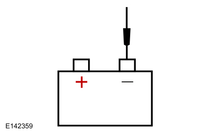
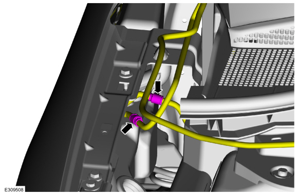
B2 MEASURE VOLTAGE DROP OF THE DCDC (DIRECT CURRENT/DIRECT CURRENT CONVERTER CONTROL MODULE) B+ CABLE
  • Measure:
    Click to display connectors

    NOTE: Place the positive lead on the DC/DC Converter B+ stud.


    Positive Lead Measurement / Action Negative Lead
    C1457C (12V DC/DC B+) 12V BATTERY B+

Is the voltage drop less than 0.5 volt?
Yes Verify the G102 body connection is OK. If not OK, REPAIR the connection. If OK, REPAIR 12V Battery B- circuit or INSTALL a new 12V battery negative cable if necessary. GO to B3 If there are NO DTC s, GO to B3
No VERIFY the high current fuse box fuse 4 (300A) is OK. If OK, REPAIR circuit. If not OK, REFER to the Wiring Diagrams manual to identify the possible causes of the circuit short. INSTALL new B+ cables, if necessary.

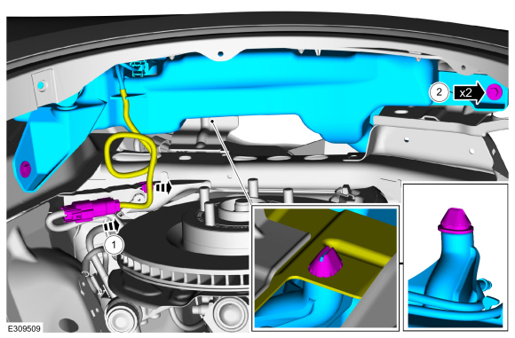
B3 VERIFY THE DCDC (DIRECT CURRENT/DIRECT CURRENT CONVERTER CONTROL MODULE) CASE GROUND
  • Start the vehicle (Ready indicator light ON).
  • Turn the headlamps on and the blower on high.
  • Measure:

    NOTE: Place the positive lead on the DC/DC Converter Case.


    Positive Lead Measurement / Action Negative Lead
    DC/DC Case

Is the voltage drop less than 0.5V?
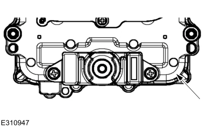
Yes DIAGNOSE the low 12V battery voltage symptom.
REFER to: Battery (414-01 Battery, Mounting and Cables, Diagnosis and Testing).
No INSPECT and REPAIR the DCDC case ground issue or the battery ground for corrosion.

PINPOINT TEST C: P0563

NOTE: The Secondary Inverter System Controller (S-ISC) is referred to as the SOBDMB (Secondary On-Board Diagnostic Control Module B) in the scan tool.

Normal Operation and Fault Conditions

REFER to: Rear Electric Drive Assembly - System Operation and Component Description (302-02 Rear Electric Drive Assembly, Description and Operation).

DTC Fault Trigger Conditions

DTC Description Fault Trigger Condition
SOBDMB P0563:00 System Voltage High: No Sub Type Information This DTC sets when the internal processor voltages are greater than a calibrated range.

Possible Sources

  • External excessive voltage
  • 24-volt jump start
  • Secondary Inverter System Controller (S-ISC)
C1 CHECK THE SECONDARY INVERTER SYSTEM CONTROLLER (S-ISC) CIRCUIT FOR VOLTAGE
  • Ignition OFF.
  • Disconnect Secondary Inverter System Controller (S-ISC) C3501 .
  • Ignition ON.
  • Measure:
    Positive Lead Measurement / Action Negative Lead
      C3501-M1   Ground

Is the voltage greater than 10.5 V?
Yes GO to C2
No DIAGNOSE the low 12V battery voltage symptom.
REFER to: Battery (414-01 Battery, Mounting and Cables, Diagnosis and Testing). Using a diagnostic scan tool, clear the Secondary Inverter System Controller (S-ISC) DTC s.

C2 CHECK THE SECONDARY INVERTER SYSTEM CONTROLLER (S-ISC) CIRCUIT FOR VOLTAGE
  • Measure:
    Positive Lead Measurement / Action Negative Lead
      C3501-K2   Ground

Is the voltage less than 16V?
Yes GO to C3
No DIAGNOSE the high 12V battery voltage symptom.
REFER to: Battery (414-01 Battery, Mounting and Cables, Diagnosis and Testing). Using a diagnostic scan tool, clear the Inverter System Controller DTC s.

C3 CHECK FOR SECONDARY INVERTER SYSTEM CONTROLLER (S-ISC) DIAGNOSTIC TROUBLE CODES (DTCS)
  • Ignition OFF.
  • Connect Secondary Inverter System Controller (S-ISC) C3501 .
  • Ignition ON.
  • Using a diagnostic scan tool, clear the Secondary Inverter System Controller (S-ISC) DTC s.
  • Allow the Secondary Inverter System Controller (S-ISC) to complete a normal power down sequence.
  • Using a diagnostic scan tool, perform the Secondary Inverter System Controller (S-ISC) self-test.

Was DTC P0563 read from the Secondary Inverter System Controller (S-ISC)?
Yes DTC P0563 frequently sets after the vehicle has been jump-started. A key cycle, followed by clearing DTC s is expected to clear this DTC , if the DTC continuously returns, INSTALL a new Secondary Inverter System Controller (S-ISC).
REFER to: Inverter System Controller [SOBDMB] (302-02 Rear Electric Drive Assembly, Removal and Installation).
No Test is complete, no faults were found.

PINPOINT TEST D: P0600:49, P0600:88, P060A:86, P060A:88

NOTE: The Secondary Inverter System Controller (S-ISC) is referred to as the SOBDMB (Secondary On-Board Diagnostic Control Module B) in the scan tool.

Normal Operation and Fault Conditions

REFER to: Rear Electric Drive Assembly - System Operation and Component Description (302-02 Rear Electric Drive Assembly, Description and Operation).

DTC Fault Trigger Conditions

DTC Description Fault Trigger Condition
SOBDMB P0600:49 Serial Communication Link: Internal Electronic Failure This DTC sets when an internal error occurs.
SOBDMB P0600:88 Serial Communication Link: Bus Off This DTC sets when an internal error occurs.
SOBDMB P060A:86 Internal Control Module Monitoring Processor Performance: Signal Invalid This DTC sets when an internal error occurs.
SOBDMB P060A:88 Internal Control Module Monitoring Processor Performance: Bus Off This DTC sets when an internal error occurs.

Possible Sources

  • Secondary Inverter System Controller (S-ISC) calibration
  • Secondary Inverter System Controller (S-ISC)
D1 CHECK FOR SECONDARY INVERTER SYSTEM CONTROLLER (S-ISC) DIAGNOSTIC TROUBLE CODES (DTCS)
  • Using a diagnostic scan tool, perform the Secondary Inverter System Controller (S-ISC) self-test.

Are any Secondary Inverter System Controller (S-ISC) DTC s other than P0600:49, P0600:88, P060A:86 or P060A:88 present?
Yes DIAGNOSE all other Secondary Inverter System Controller (S-ISC) DTC s, REFER to the DTC chart in this section.
No For DTC P0600:49, P0600:88, P060A:86 or P060A:88 only GO to D2

D2 VERIFY THE SECONDARY INVERTER SYSTEM CONTROLLER (S-ISC) CALIBRATION LEVEL
  • Verify the Secondary Inverter System Controller (S-ISC) is at the latest calibration level.

Is the Secondary Inverter System Controller (S-ISC) at the latest calibration level?
Yes GO to D3
No UPDATE the Secondary Inverter System Controller (S-ISC) to the latest calibration level.

D3 CLEAR AND CHECK SECONDARY INVERTER SYSTEM CONTROLLER (S-ISC) DIAGNOSTIC TROUBLE CODES (DTCS)
  • Using a diagnostic scan tool, clear the Secondary Inverter System Controller (S-ISC) DTC s.
  • Using a diagnostic scan tool, perform the Secondary Inverter System Controller (S-ISC) self-test.

Are DTC s P0600:49, P0600:88, P060A:86 or P060A:88 present?
Yes CHECK OASIS for any applicable service articles: TSB , GSB , SSM or FSA . If a service article exists for this concern, DISCONTINUE this test and FOLLOW the service article instructions. If no service articles address this concern, INSTALL a new Secondary Inverter System Controller (S-ISC).
REFER to: Inverter System Controller [SOBDMB] (302-02 Rear Electric Drive Assembly, Removal and Installation).
No The system is operating correctly at this time. The DTC may have been set due to high network traffic or an intermittent fault condition.

PINPOINT TEST E: P060A:4A

NOTE: The Secondary Inverter System Controller (S-ISC) is referred to as the SOBDMB (Secondary On-Board Diagnostic Control Module B) in the scan tool.

Normal Operation and Fault Conditions

REFER to: Rear Electric Drive Assembly - System Operation and Component Description (302-02 Rear Electric Drive Assembly, Description and Operation).

DTC Fault Trigger Conditions

DTC Description Fault Trigger Condition
SOBDMB P060A:4A Internal Control Module Monitoring Processor Performance: Incorrect Component Installed This DTC sets with other DTC s due to external wiring issues, and sets alone when an internal error occurs.

Possible Sources

  • Secondary Inverter System Controller (S-ISC) calibration
  • Secondary Inverter System Controller (S-ISC)
  • Intermittent low voltage wiring concern
  • Wiring, terminals or connectors
E1 CHECK FOR SECONDARY INVERTER SYSTEM CONTROLLER (S-ISC) DIAGNOSTIC TROUBLE CODES (DTCS)

NOTE: P060A:4A very commonly sets with (and due to) many other S-ISC DTCs, it would be very rare to see these DTCs alone.

  • Using a diagnostic scan tool, perform the Secondary Inverter System Controller (S-ISC) self-test.

Are any Secondary Inverter System Controller (S-ISC) DTC s other than P060A:44 present?
Yes DIAGNOSE all other Secondary Inverter System Controller (S-ISC) DTC s, REFER to the DTC chart in this section.
No For DTC P060A:44 only GO to E2

E2 VERIFY THE SECONDARY INVERTER SYSTEM CONTROLLER (S-ISC) CALIBRATION LEVEL
  • Verify the Secondary Inverter System Controller (S-ISC) is at the latest calibration level.

Is the Secondary Inverter System Controller (S-ISC) at the latest calibration level?
Yes GO to E3
No UPDATE the Secondary Inverter System Controller (S-ISC) to the latest calibration level.

E3 CLEAR AND CHECK THE SECONDARY INVERTER SYSTEM CONTROLLER (S-ISC) DIAGNOSTIC TROUBLE CODES (DTCS)
  • Using a diagnostic scan tool, clear the Secondary Inverter System Controller (S-ISC) DTC s.
  • Ignition OFF.
  • Wait 5 minutes.
  • Ignition ON.
  • Wait 5 minutes.
  • Using a diagnostic scan tool, perform the Secondary Inverter System Controller (S-ISC) self-test.

Is DTC P060A:4A present in the Secondary Inverter System Controller (S-ISC)?
Yes CHECK OASIS for any applicable service articles: TSB , GSB , SSM or FSA . If a service article exists for this concern, DISCONTINUE this test and FOLLOW the service article instructions. If no service articles address this concern, INSTALL a new Secondary Inverter System Controller (S-ISC).
REFER to: Inverter System Controller [SOBDMB] (302-02 Rear Electric Drive Assembly, Removal and Installation).
No The system is operating correctly at this time. The DTC may have been set due to high network traffic or an intermittent fault condition.

PINPOINT TEST F: P060A:44, P060A:47

NOTE: The Secondary Inverter System Controller (S-ISC) is referred to as the SOBDMB (Secondary On-Board Diagnostic Control Module B) in the scan tool.

Normal Operation and Fault Conditions

REFER to: Rear Electric Drive Assembly - System Operation and Component Description (302-02 Rear Electric Drive Assembly, Description and Operation).

DTC Fault Trigger Conditions

DTC Description Fault Trigger Condition
SOBDMB P060A:44 Internal Control Module Monitoring Processor Performance: Data Memory Failure This DTC sets when an internal error occurs.
SOBDMB P060A:47 Internal Control Module Monitoring Processor Performance: Watchdog/Safety µC Failure This DTC sets when an internal error occurs.

Possible Sources

  • Secondary Inverter System Controller (S-ISC) calibration
  • Secondary Inverter System Controller (S-ISC)
F1 CHECK FOR SECONDARY INVERTER SYSTEM CONTROLLER (S-ISC) DIAGNOSTIC TROUBLE CODES (DTCS)
  • Using a diagnostic scan tool, perform the Secondary Inverter System Controller (S-ISC) self-test.

Are any Secondary Inverter System Controller (S-ISC) DTC s other than P060A:44 or P060A:47 present?
Yes DIAGNOSE all other Secondary Inverter System Controller (S-ISC) DTC s, REFER to the DTC chart in this section.
No For DTC P060A:44 or P060A:47 only GO to F2

F2 VERIFY THE SECONDARY INVERTER SYSTEM CONTROLLER (S-ISC) CALIBRATION LEVEL
  • Verify the Secondary Inverter System Controller (S-ISC) is at the latest calibration level.

Is the Secondary Inverter System Controller (S-ISC) at the latest calibration level?
Yes GO to F3
No UPDATE the Secondary Inverter System Controller (S-ISC) to the latest calibration level.

F3 CLEAR AND CHECK THE SECONDARY INVERTER SYSTEM CONTROLLER (S-ISC) DIAGNOSTIC TROUBLE CODES (DTCS)
  • Using a diagnostic scan tool, clear the Secondary Inverter System Controller (S-ISC) DTC s.
  • Using a diagnostic scan tool, perform the Secondary Inverter System Controller (S-ISC) self-test.

Are DTC s P060A:44 or P060A:47 present in the Secondary Inverter System Controller (S-ISC)?
Yes CHECK OASIS for any applicable service articles: TSB , GSB , SSM or FSA . If a service article exists for this concern, DISCONTINUE this test and FOLLOW the service article instructions. If no service articles address this concern, INSTALL a new Secondary Inverter System Controller (S-ISC).
REFER to: Inverter System Controller [SOBDMB] (302-02 Rear Electric Drive Assembly, Removal and Installation).
No The system is operating correctly at this time. The DTC may have been set due to high network traffic or an intermittent fault condition.

PINPOINT TEST G: P060B:47, P060B:62

NOTE: The Secondary Inverter System Controller (S-ISC) is referred to as the SOBDMB (Secondary On-Board Diagnostic Control Module B) in the scan tool.

Normal Operation and Fault Conditions

REFER to: Rear Electric Drive Assembly - System Operation and Component Description (302-02 Rear Electric Drive Assembly, Description and Operation).

DTC Fault Trigger Conditions

DTC Description Fault Trigger Condition
SOBDMB P060B:47 Internal Control Module A/D Processing Performance: Watchdog/Safety µC Failure This DTC sets with other DTC s due to external wiring issues, and sets alone when an internal error occurs.
SOBDMB P060B:62 Internal Control Module A/D Processing Performance: Signal Compare Failure This DTC sets with other DTC s due to external wiring issues, and sets alone when an internal error occurs.

Possible Sources

  • Secondary Inverter System Controller (S-ISC) calibration
  • Intermittent low voltage wiring concern
  • Wiring, terminals or connectors
  • Secondary Inverter System Controller (S-ISC)
G1 CHECK FOR SECONDARY INVERTER SYSTEM CONTROLLER (S-ISC) DIAGNOSTIC TROUBLE CODES (DTCS)

NOTE: DTCs P060B:47 and P060B:62 are commonly set and due to other Secondary Inverter System Controller (S-ISC) DTCs.

  • Using a diagnostic scan tool, perform the Secondary Inverter System Controller (S-ISC) self-test.

Are any Secondary Inverter System Controller (S-ISC) DTC s other than P060B:47 or P060B:62 present?
Yes DIAGNOSE all other Secondary Inverter System Controller (S-ISC) DTC s, REFER to the DTC chart in this section.
No For DTC P060B:47 or P060B:62 only GO to G2

G2 VERIFY THE SECONDARY INVERTER SYSTEM CONTROLLER (S-ISC) CALIBRATION LEVEL
  • Verify the Secondary Inverter System Controller (S-ISC) is at the latest calibration level.

Is the Secondary Inverter System Controller (S-ISC) at the latest calibration level?
Yes GO to G3
No UPDATE the Secondary Inverter System Controller (S-ISC) to the latest calibration level.

G3 CLEAR AND CHECK THE SECONDARY INVERTER SYSTEM CONTROLLER (S-ISC) DIAGNOSTIC TROUBLE CODES (DTCS)
  • Using a diagnostic scan tool, clear the Secondary Inverter System Controller (S-ISC) DTC s.
  • Ignition OFF.
  • Wait 5 minutes.
  • Ignition ON.
  • Wait 5 minutes.
  • Using a diagnostic scan tool, perform the Secondary Inverter System Controller (S-ISC) self-test.

Are DTC s P060B:47 or P060B:62 present in the Secondary Inverter System Controller (S-ISC)?
Yes CHECK OASIS for any applicable service articles: TSB , GSB , SSM or FSA . If a service article exists for this concern, DISCONTINUE this test and FOLLOW the service article instructions. If no service articles address this concern, INSTALL a new Secondary Inverter System Controller (S-ISC).
REFER to: Inverter System Controller [SOBDMB] (302-02 Rear Electric Drive Assembly, Removal and Installation).
No The system is operating correctly at this time. The DTC may have been set due to high network traffic or an intermittent fault condition.

PINPOINT TEST H: P060C:41, P060C:42, P060C:44, P060C:47

NOTE: The Secondary Inverter System Controller (S-ISC) is referred to as the SOBDMB (Secondary On-Board Diagnostic Control Module B) in the scan tool.

Normal Operation and Fault Conditions

REFER to: Rear Electric Drive Assembly - System Operation and Component Description (302-02 Rear Electric Drive Assembly, Description and Operation).

DTC Fault Trigger Conditions

DTC Description Fault Trigger Condition
SOBDMB P060C:41 Internal Control Module Main Processor Performance: General Checksum Failure This DTC sets when an internal error occurs.
SOBDMB P060C:42 Internal Control Module Main Processor Performance: General Memory Failure This DTC sets when an internal error occurs.
SOBDMB P060C:44 Internal Control Module Main Processor Performance: Data Memory Failure This DTC sets when an internal error occurs.
SOBDMB P060C:47 Internal Control Module Main Processor Performance: Watchdog/Safety µC Failure This DTC sets when an internal error occurs.

Possible Sources

  • Secondary Inverter System Controller (S-ISC) calibration
  • Secondary Inverter System Controller (S-ISC)
H1 CHECK FOR SECONDARY INVERTER SYSTEM CONTROLLER (S-ISC) DIAGNOSTIC TROUBLE CODES (DTCS)
  • Using a diagnostic scan tool, perform the Secondary Inverter System Controller (S-ISC) self-test.

Are any Secondary Inverter System Controller (S-ISC) DTC s other than P060C:41, P060C:42, P060C:44 or P060C:47 present?
Yes DIAGNOSE all other Secondary Inverter System Controller (S-ISC) DTC s, REFER to the DTC chart in this section.
No For DTC P060C:41, P060C:42, P060C:44 or P060C:47 only GO to H2

H2 VERIFY ALL CAN MODULE CALIBRATION LEVELS
  • Verify all CAN modules are at the latest calibration level.

Are all CAN modules are at the latest calibration level?
Yes GO to H3
No UPDATE the all CAN modules to the latest calibration level.

H3 CLEAR AND CHECK THE SECONDARY INVERTER SYSTEM CONTROLLER (S-ISC) DIAGNOSTIC TROUBLE CODES (DTCS)
  • Using a diagnostic scan tool, clear the Secondary Inverter System Controller (S-ISC) DTC s.
  • Using a diagnostic scan tool, perform the Secondary Inverter System Controller (S-ISC) self-test.

Are DTC s P060C:41, P060C:42, P060C:44 or P060C:47 present in the Secondary Inverter System Controller (S-ISC)?
Yes CHECK OASIS for any applicable service articles: TSB , GSB , SSM or FSA . If a service article exists for this concern, DISCONTINUE this test and FOLLOW the service article instructions. If no service articles address this concern, INSTALL a new Secondary Inverter System Controller (S-ISC).
REFER to: Inverter System Controller [SOBDMB] (302-02 Rear Electric Drive Assembly, Removal and Installation).
No The system is operating correctly at this time. The DTC may have been set due to high network traffic or an intermittent fault condition.

PINPOINT TEST I: P0613:86

NOTE: The Secondary Inverter System Controller (S-ISC) is referred to as the SOBDMB (Secondary On-Board Diagnostic Control Module B) in the scan tool.

NOTE: P0613 generally sets as a result of other DTCs which should be diagnosed first. P0613 rarely sets alone.

Normal Operation and Fault Conditions

REFER to: Rear Electric Drive Assembly - System Operation and Component Description (302-02 Rear Electric Drive Assembly, Description and Operation).

DTC Fault Trigger Conditions

DTC Description Fault Trigger Condition
SOBDMB P0613:86 TCM Processor: Signal Invalid This DTC sets when an internal error occurs, or other DTC s have set.

Possible Sources

  • Other Secondary Inverter System Controller (S-ISC) DTC s
  • Secondary Inverter System Controller (S-ISC) calibration
  • Secondary Inverter System Controller (S-ISC)
I1 CHECK FOR SECONDARY INVERTER SYSTEM CONTROLLER (S-ISC) DIAGNOSTIC TROUBLE CODES (DTCS)
  • Using a diagnostic scan tool, perform the Secondary Inverter System Controller (S-ISC) self-test.

Are any Secondary Inverter System Controller (S-ISC) DTC s other than P0613:86 present?
Yes DIAGNOSE all other Secondary Inverter System Controller (S-ISC) DTC s, REFER to the DTC chart in this section.
No For DTC P0613:86 only GO to I2

I2 VERIFY THE SECONDARY INVERTER SYSTEM CONTROLLER (S-ISC) CALIBRATION LEVEL
  • Verify the Secondary Inverter System Controller (S-ISC) is at the latest calibration level.

Is the Secondary Inverter System Controller (S-ISC) at the latest calibration level?
Yes GO to I3
No UPDATE the Secondary Inverter System Controller (S-ISC) to the latest calibration level.

I3 CLEAR AND CHECK THE SECONDARY INVERTER SYSTEM CONTROLLER (S-ISC) DIAGNOSTIC TROUBLE CODES (DTCS)
  • Using a diagnostic scan tool, clear the Secondary Inverter System Controller (S-ISC) DTC s.
  • Using a diagnostic scan tool, perform the Secondary Inverter System Controller (S-ISC) self-test.

Is DTC P0613:86 only DTC present in the Secondary Inverter System Controller (S-ISC)?
Yes CHECK OASIS for any applicable service articles: TSB , GSB , SSM or FSA . If a service article exists for this concern, DISCONTINUE this test and FOLLOW the service article instructions. If no service articles address this concern and this is the only DTC present, INSTALL a new Secondary Inverter System Controller (S-ISC).
REFER to: Inverter System Controller [SOBDMB] (302-02 Rear Electric Drive Assembly, Removal and Installation).
No DIAGNOSE any other remaining Secondary Inverter System Controller (S-ISC) DTC s.

PINPOINT TEST J: P0634

NOTE: The Secondary Inverter System Controller (S-ISC) is referred to as the SOBDMB (Secondary On-Board Diagnostic Control Module B) in the scan tool.

Normal Operation and Fault Conditions

REFER to: Rear Electric Drive Assembly - System Operation and Component Description (302-02 Rear Electric Drive Assembly, Description and Operation).

DTC Fault Trigger Conditions

DTC Description Fault Trigger Condition
SOBDMB P0634:00 Control Module Internal Temperature 'A' Too High: No Sub Type Information This DTC sets when the internal circuit board reports an over-temperature condition.

Possible Sources

  • Electric Powertrain Cooling Concern
  • Secondary Inverter System Controller (S-ISC)
J1 CHECK FOR SECONDARY INVERTER SYSTEM CONTROLLER (S-ISC) DIAGNOSTIC TROUBLE CODES (DTCS)
  • Ignition ON.
  • Using a diagnostic scan tool, perform the Secondary Inverter System Controller (S-ISC) self-test.
  • Record the Secondary Inverter System Controller (S-ISC) DTC s
  • Using a diagnostic scan tool, perform the BECM self-test.
  • Record the BECM s

Are any Secondary Inverter System Controller (S-ISC) or BECM DTC s present?
Yes For BECM DTC s
REFER to: High Voltage Battery, Mounting and Cables - Plug-In Hybrid Electric Vehicle (PHEV) (414-03A High Voltage Battery, Mounting and Cables, Diagnosis and Testing). For Secondary Inverter System Controller (S-ISC) DTC s, DIAGNOSE all other Secondary Inverter System Controller (S-ISC) DTC s other than P0634 first, REFER to the DTC chart in this section.
No GO to J2

J2 CHECK THE COOLING FAN AND ACTIVE GRILLE SHUTTER OPERATION

NOTE: Verify radiator cooling fan operation before proceeding with this test

  • Verify the cooling fan and active grille shutters operate correctly.

Do the active grille shutters and cooling fan operate correctly?
Yes GO to J3
No
REFER to: Active Grille Shutter (501-02 Front End Body Panels, Diagnosis and Testing).

J3 CHECK THE COOLANT LEVEL
  • Inspect the coolant.

Is the coolant at the correct level?
Yes GO to J5
No
REFER to: Cooling System Filling and Bleeding (303-03D Electric Powertrain Cooling - 2.5L Duratec – Hybrid (121kW/164PS) (BG), General Procedures).

J4 CHECK FOR A RECENT COOLANT FILL
  • Inspect the coolant for signs of a recent fill.

Has the coolant system been recently filled?
Yes PERFORM the system fill procedure to bleed air from the system, add coolant if needed.
REFER to: Cooling System Filling and Bleeding (303-03D Electric Powertrain Cooling - 2.5L Duratec – Hybrid (121kW/164PS) (BG), General Procedures).
No GO to J5

J5 INSPECT THE COOLANT FOR CONTAMINATION
  • Inspect the coolant.

Is the coolant contaminated?
Yes
REFER to: Cooling System Filling and Bleeding (303-03D Electric Powertrain Cooling - 2.5L Duratec – Hybrid (121kW/164PS) (BG), General Procedures).
No GO to J6

J6 INSPECT THE RADIATOR
  • Inspect the radiator for any obstruction.

Is the radiator obstructed?
Yes REPAIR as necessary.
No GO to J7

J7 INSPECT THE MOTOR ELECTRONICS COOLING SYSTEM HOSES
  • Inspect the motor electronics cooling system hoses for kinks, leaks, improper routing or connections.

Is a concern present?
Yes REPAIR as necessary.
No GO to J8

J8 INSPECT FOR INTERNAL AND EXTERNAL COOLANT LEAKS
  • Inspect the coolant system for leaks.

Are any leaks present?
Yes REPAIR as necessary.
No GO to J9

J9 CLEAR AND CHECK THE SECONDARY INVERTER SYSTEM CONTROLLER (S-ISC) DIAGNOSTIC TROUBLE CODES (DTCS)
  • Using a diagnostic scan tool, clear the Secondary Inverter System Controller (S-ISC) DTC s.
  • Using a diagnostic scan tool, perform the Secondary Inverter System Controller (S-ISC) self-test.

Is DTC P064F:00 the only DTC present in the Secondary Inverter System Controller (S-ISC)?
Yes CHECK OASIS for any applicable service articles: TSB , GSB , SSM or FSA . If a service article exists for this concern, DISCONTINUE this test and FOLLOW the service article instructions. If no service articles address this concern, INSTALL a new Secondary Inverter System Controller (S-ISC).
REFER to: Inverter System Controller [SOBDMB] (302-02 Rear Electric Drive Assembly, Removal and Installation).
No DIAGNOSE any remaining Secondary Inverter System Controller (S-ISC) DTC s.

PINPOINT TEST K: P064F

NOTE: The Secondary Inverter System Controller (S-ISC) is referred to as the SOBDMB (Secondary On-Board Diagnostic Control Module B) in the scan tool.

Normal Operation and Fault Conditions

REFER to: Rear Electric Drive Assembly - System Operation and Component Description (302-02 Rear Electric Drive Assembly, Description and Operation).

DTC Fault Trigger Conditions

DTC Description Fault Trigger Condition
SOBDMB P064F:00 Unauthorized Software/Calibration Detected: No Sub Type Information This DTC sets when the Secondary Inverter System Controller (S-ISC) has not been flashed with production intent software.

Possible Sources

  • Secondary Inverter System Controller (S-ISC) calibration
K1 REPROGRAM OR UPDATE THE CALIBRATION
  • Reprogram or update the calibration.

Was the programming of the Secondary Inverter System Controller (S-ISC) successful?
Yes GO to K2
No CHECK OASIS for any applicable service articles: TSB , GSB , SSM or FSA . If a service article exists for this concern, ENSURE the 12V Maintainer is installed on the vehicle, check CAN connections, then attempt reflash.
REFER to: Module Programming (418-01 Module Configuration, General Procedures).

K2 CLEAR AND CHECK THE SECONDARY INVERTER SYSTEM CONTROLLER (S-ISC) DIAGNOSTIC TROUBLE CODES (DTCS)
  • Using a diagnostic scan tool, clear the Secondary Inverter System Controller (S-ISC) DTC s.
  • Using a diagnostic scan tool, perform the Secondary Inverter System Controller (S-ISC) self-test.

Is DTC P064F:00 present in the Secondary Inverter System Controller (S-ISC)?
Yes CHECK OASIS for any applicable service articles: TSB , GSB , SSM or FSA . If a service article exists for this concern, DISCONTINUE this test and FOLLOW the service article instructions. If no service articles address this concern, it is necessary to seek additional help. REFER to the Service Repair And Technical Assistance Process. A vehicle data recorder (VDR) or similar recorder may also be useful.
No The system is operating correctly at this time. The DTC may have been set due to high network traffic or an intermittent fault condition.

PINPOINT TEST L: P06A6, P06A7, P06A9, P06B1, P0A23

NOTE: The Secondary Inverter System Controller (S-ISC) is referred to as the SOBDMB (Secondary On-Board Diagnostic Control Module B) in the scan tool.

Normal Operation and Fault Conditions

REFER to: Rear Electric Drive Assembly - System Operation and Component Description (302-02 Rear Electric Drive Assembly, Description and Operation).

DTC Fault Trigger Conditions

DTC Description Fault Trigger Condition
SOBDMB P06A6:00 Sensor Reference Voltage 'A' Circuit Range/Performance: No Sub Type Information This DTC sets when an internal power supply failure is indicated.
SOBDMB P06A7:00 Sensor Reference Voltage 'B' Circuit Range/Performance: No Sub Type Information This DTC sets when an internal power supply failure is indicated.
SOBDMB P06A9:00 Sensor Reference Voltage 'D' Circuit Range/Performance: No Sub Type Information This DTC sets when the generator resolver 5 volt power supply is out of range.
SOBDMB P06B1:00 Sensor Power Supply 'A' Circuit Low: No Sub Type Information This DTC sets when an internal power supply failure is indicated.
SOBDMB P0A23:00 Generator Torque Sensor Circuit Range/Performance: No Sub Type Information This DTC sets when the generator current sensor is out of range.

Possible Sources

  • Wiring, terminals or connectors
  • Secondary Inverter System Controller (S-ISC) calibration
  • Secondary Inverter System Controller (S-ISC)
L1 CHECK FOR SECONDARY INVERTER SYSTEM CONTROLLER (S-ISC) DIAGNOSTIC TROUBLE CODES (DTCS)
  • Using a diagnostic scan tool, retrieve all Secondary Inverter System Controller (S-ISC) DTC s.

Are any Secondary Inverter System Controller (S-ISC) DTC s other than P06A6:00, P06A7:00, P06A9, P06B1:00 or P0A23:00 present?
Yes DIAGNOSE all other Secondary Inverter System Controller (S-ISC) DTC s, REFER to the DTC chart in this section.
No For DTC P06A6:00, P06A7:00, P06A9, P06B1:00 or P0A23:00 only GO to L2

L2 VERIFY THE SECONDARY INVERTER SYSTEM CONTROLLER (S-ISC) CALIBRATION LEVEL
  • Verify the Secondary Inverter System Controller (S-ISC) is at the latest calibration level.

Is the Secondary Inverter System Controller (S-ISC) at the latest calibration level?
Yes GO to L3
No UPDATE the Secondary Inverter System Controller (S-ISC) to the latest calibration level.

L3 CLEAR AND CHECK SECONDARY INVERTER SYSTEM CONTROLLER (S-ISC) DIAGNOSTIC TROUBLE CODES (DTCS)
  • Using a diagnostic scan tool, clear all Secondary Inverter System Controller (S-ISC) DTC s.
  • Using a diagnostic scan tool, retrieve all Secondary Inverter System Controller (S-ISC) DTC s.

Are DTC s P06A6:00, P06A7:00, P06A9, P06B1:00 or P0A23:00 present?
Yes CHECK OASIS for any applicable service articles: TSB , GSB , SSM or FSA . If a service article exists for this concern, DISCONTINUE this test and FOLLOW the service article instructions. If no service articles address this concern, INSTALL a new Secondary Inverter System Controller (S-ISC).
REFER to: Inverter System Controller [SOBDMB] (302-02 Rear Electric Drive Assembly, Removal and Installation).
No The system is operating correctly at this time. The DTC may have been set due to high network traffic or an intermittent fault condition.

PINPOINT TEST M: P06B8

NOTE: The Secondary Inverter System Controller (S-ISC) is referred to as the SOBDMB (Secondary On-Board Diagnostic Control Module B) in the scan tool.

Normal Operation and Fault Conditions

REFER to: Rear Electric Drive Assembly - System Operation and Component Description (302-02 Rear Electric Drive Assembly, Description and Operation).

DTC Fault Trigger Conditions

DTC Description Fault Trigger Condition
SOBDMB P06B8:00 Internal Control Module Non-Volatile Random Access Memory (NVRAM) Error: No Sub Type Information This DTC sets when an internal error occurs.

Possible Sources

  • Secondary Inverter System Controller (S-ISC) calibration
  • Secondary Inverter System Controller (S-ISC)
M1 VERIFY THE SECONDARY INVERTER SYSTEM CONTROLLER (S-ISC) CALIBRATION LEVEL
  • Verify the Secondary Inverter System Controller (S-ISC) is at the latest calibration level.

Is the Secondary Inverter System Controller (S-ISC) at the latest calibration level?
Yes GO to M2
No UPDATE the Secondary Inverter System Controller (S-ISC) to the latest calibration level.

M2 CLEAR AND CHECK THE SECONDARY INVERTER SYSTEM CONTROLLER (S-ISC) DIAGNOSTIC TROUBLE CODES (DTCS)
  • Using a diagnostic scan tool, clear the Secondary Inverter System Controller (S-ISC) DTC s.
  • Using a diagnostic scan tool, perform the Secondary Inverter System Controller (S-ISC) self-test.

Is DTC P06B8:00 present in the Secondary Inverter System Controller (S-ISC)?
Yes CHECK OASIS for any applicable service articles: TSB , GSB , SSM or FSA . If a service article exists for this concern, DISCONTINUE this test and FOLLOW the service article instructions. If no service articles address this concern, INSTALL a new Secondary Inverter System Controller (S-ISC).
REFER to: Inverter System Controller [SOBDMB] (302-02 Rear Electric Drive Assembly, Removal and Installation).
No The system is operating correctly at this time. The DTC may have been set due to high network traffic or an intermittent fault condition.

PINPOINT TEST N: P0887

NOTE: The Secondary Inverter System Controller (S-ISC) is referred to as the SOBDMB (Secondary On-Board Diagnostic Control Module B) in the scan tool.

Normal Operation and Fault Conditions

REFER to: Rear Electric Drive Assembly - System Operation and Component Description (302-02 Rear Electric Drive Assembly, Description and Operation).

DTC Fault Trigger Conditions

DTC Description Fault Trigger Condition
SOBDMB P0887:00 TCM Power Relay Control Circuit High: No Sub Type Information This DTC sets when a short to power or open is detected on the relay control circuit.

Possible Sources

  • Wiring, terminals or connectors
  • BCM
  • Primary ISC SOBDMC power relay control circuit
N1 CHECK FOR LOW VOLTAGE BECM (BATTERY ENERGY CONTROL MODULE) DIAGNOSTIC TROUBLE CODES (DTCS)

NOTE: Turn the ignition OFF for 5 minutes before carrying out the self-test or clearing DTCs.

NOTE: DTC P0887 may set as a result of a low 12 volt battery concern or loose connections to the 12V battery or ground.

NOTE: DTCs P0562 or U3003 may set in any module in addition to DTC P0887 being set in the Secondary Inverter System Controller (S-ISC). Diagnose all other low 12V DTCs before entering this pinpoint test.

NOTE: DTC P0887 may set in the SOBDM-B due to P0887 being set in the SOBDM-C.

  • Ignition ON.
  • Using a diagnostic scan tool, retrieve all DTC s.

Are there any DTC s related to the 12V battery present?
Yes DIAGNOSE all 12V battery DTC s.
No GO to N2

N2 CHECK FOR LOW VOLTAGE PRIMARY INVERTER SYSTEM CONTROLLER (ISC) DIAGNOSTIC TROUBLE CODES (DTCS)

NOTE: The key cycle is very important, the DTC will not clear unless a key cycle is completed.

  • Ignition OFF.
  • Wait 5 minutes.
  • Ignition ON.
  • Using a diagnostic scan tool, retrieve the Primary Inverter System Controller (ISC) CMDTC s.

Is DTC P0887 present in the Primary Inverter System Controller (ISC)?
Yes
REFER to: Electric Powertrain Control (303-14D Electric Powertrain Control, Diagnosis and Testing).
No GO to N3

N3 CHECK FOR LOW VOLTAGE SECONDARY INVERTER SYSTEM CONTROLLER (S-ISC) DIAGNOSTIC TROUBLE CODES (DTCS)

NOTE: The key cycle is very important, the DTC will not clear unless a key cycle is completed.

  • Ignition OFF.
  • Wait 5 minutes.
  • Ignition ON.
  • Using a diagnostic scan tool, clear the Secondary Inverter System Controller (S-ISC) DTC s.
  • Using a diagnostic scan tool, perform the Secondary Inverter System Controller (S-ISC) self-test.

Is DTC P0887 present in the Secondary Inverter System Controller (S-ISC)?
Yes GO to N4
No The system is operating correctly at this time. The DTC may have been set due to high network traffic or an intermittent fault condition.

N4 CHECK THE BATTERY AND CHARGING SYSTEM
  • Check the battery and charging system voltages.
    REFER to: Battery Drain Check (414-01 Battery, Mounting and Cables, General Procedures).

Are the battery and charging system voltages within specification?
Yes GO to N8
No REPAIR as necessary.
REFER to: Battery (414-01 Battery, Mounting and Cables, Diagnosis and Testing). Clear the inverter System Controller (ISC) DTC s. REPEAT the self-test.

N5 CHECK FOR CORRECT SECONDARY INVERTER SYSTEM CONTROLLER (S-ISC) OPERATION
  • Ignition OFF.
  • Disconnect and inspect all Secondary Inverter System Controller (S-ISC) connectors.
  • Repair:
    • corrosion (install new connector or terminals – clean module pins)
    • damaged or bent pins – install new terminals/pins
    • pushed-out pins – install new pins as necessary
  • Reconnect the Secondary Inverter System Controller (S-ISC) connectors. Make sure they seat and latch correctly.
  • Operate the system and determine if the concern is still present.

Is the concern still present?
Yes GO to N6
No The system is operating correctly at this time. The concern may have been caused by module connections. ADDRESS the root cause of any connector or pin issues.

N6 INTERMITTENT CHECK
  • Access the  SOBDMB  and monitor the  ECU_VPWR (V)  PID

  • While observing, the PID s carry out the following:
    • Carefully wiggle all accessible wiring and connectors associated with the Secondary Inverter System Controller (S-ISC)
    • Wiggle the Secondary Inverter System Controller (S-ISC) connectors and harnesses
    • Look for sudden changes in voltage when the harness and connectors are wiggled

Are any concerns present?
Yes REPAIR as necessary. CLEAR the Secondary Inverter System Controller (S-ISC) DTC s. REPEAT the self-test
No GO to N7

N7 CHECK THE SECONDARY INVERTER SYSTEM CONTROLLER (S-ISC) VPWR CIRCUITS FOR AN OPEN
  • Ignition OFF.
  • Disconnect Secondary Inverter System Controller (S-ISC) C3501 .
  • Disconnect BCMC C1002 .
  • Measure:
    Positive Lead Measurement / Action Negative Lead
      C1002-30   C3501-L2
      C1002-30   C3501-M2

Is the resistance less than 5 ohms?
Yes GO to N8
No With the aid of the wiring diagram, REPAIR the open circuit.

N8 CHECK THE SECONDARY INVERTER SYSTEM CONTROLLER (S-ISC) VPWR CIRCUITS FOR A SHORT TO GROUND
  • Ignition ON.
  • Measure:
    Positive Lead Measurement / Action Negative Lead
      C3501-L2   Ground
      C3501-M2   Ground

Is the resistance greater than 10K ohms?
Yes GO to N9
No With the aid of the wiring diagram, REPAIR the short circuit.

N9 CHECK THE SECONDARY INVERTER SYSTEM CONTROLLER (S-ISC) GROUND CIRCUITS
  • Ignition ON.
  • Measure:
    Positive Lead Measurement / Action Negative Lead
      C3501-L2   CG400
      C3501-M2   CG400

Are the resistances less than 3 ohms?
Yes The system is operating correctly at this time. The concern may have been caused by module connections. Address the root cause of any connector or pin issues.
No With the aid of the wiring diagram, REPAIR the circuit.

PINPOINT TEST O: P0A0A:13

NOTE: The Secondary Inverter System Controller (S-ISC) is referred to as the SOBDMB (Secondary On-Board Diagnostic Control Module B) in the scan tool.


Refer to Wiring Diagrams Cell 12 for schematic and connector information.

Normal Operation and Fault Conditions

REFER to: Rear Electric Drive Assembly - System Operation and Component Description (302-02 Rear Electric Drive Assembly, Description and Operation).

DTC Fault Trigger Conditions

DTC Description Fault Trigger Condition
SOBDMB P0A0A:13 High Voltage System Interlock Circuit 'A': Circuit Open This DTC sets when a high voltage interlock circuit at the Secondary Inverter System Controller (S-ISC) goes open.

Possible Sources

  • Wiring, terminals or connectors
  • Secondary Inverter System Controller (S-ISC)

  WARNING: To prevent the risk of high-voltage shock, always follow precisely all warnings and service instructions, including instructions to depower the system. The high-voltage system utilizes approximately 300 volts DC, provided through high-voltage cables to its components and modules. The high-voltage cables and wiring are identified by orange harness tape or orange wire covering. All high-voltage components are marked with high-voltage warning labels with a high-voltage symbol. Failure to follow these instructions may result in serious personal injury or death.

NOTE: Use the correct probe adapter(s) from the Flex Probe Kit when taking measurements. Failure to use the correct probe adapter(s) may damage the connector.

O1 REVIEW AND RECORD THE INTERLOCK DIAGNOSTIC TROUBLE CODES (DTCS)
  • Ignition ON.
  • Using a scan tool, clear all DTC s.
  • Using a scan tool, perform the Secondary Inverter System Controller (S-ISC) self-test and record the DTC s.

Is DTC P0A0A:13 present?
Yes GO to O3
No The concern is not present at this time. The concern may be have been related to prior repair or service that included disconnecting the service disconnect or a high voltage cable.

O2 INSPECT THE SECONDARY INVERTER SYSTEM CONTROLLER (S-ISC) CONNECTOR
  • Ignition OFF.
  • Depower the high voltage system.
    REFER to: High Voltage System De-energizing (414-03A High Voltage Battery, Mounting and Cables, General Procedures).
  • Check that the Secondary Inverter System Controller (S-ISC) C4210A is fully seated.

Is the connector fully seated?
Yes GO to O3
No Repair as necessary. CLEAR the DTC s and REPEAT the self-test.

O3 CHECK FOR AN OPEN IN THE HIGH VOLTAGE CABLE INTERLOCK STAPLE
  • Disconnect Secondary Inverter System Controller (S-ISC) C4210A .
  • Measure:
    Click to display connectors
    Positive Lead Measurement / Action Negative Lead
      C4210A-2   C4210A-3

Is the resistance less than 3 ohms?
Yes GO to O4
No INSTALL a new (14B322) High Voltage cable assembly.

O4 CHECK FOR CORRECT SECONDARY INVERTER SYSTEM CONTROLLER (S-ISC) OPERATION
  • Inspect Secondary Inverter System Controller (S-ISC) C4210A interlock pins.
  • For:
    • corrosion
    • damaged or bent pins
    • pushed-out pins
  • If any concerns are present INSTALL a new (14B322) high voltage cable.
    REFER to: High Voltage Battery Cables - Plug-In Hybrid Electric Vehicle (PHEV) (414-03A High Voltage Battery, Mounting and Cables, Removal and Installation).
  • Reconnect the Secondary Inverter System Controller (S-ISC) C4210A. Make sure it seats and latches correctly.
  • Operate the system and determine if the concern is still present.

Is the concern still present?
Yes GO to O5
No The system is operating correctly at this time. The concern may have been caused by module connections. Address the root cause of any connector or pin issues.

O5 CHECK FOR SECONDARY INVERTER SYSTEM CONTROLLER (S-ISC) DIAGNOSTIC TROUBLE CODES (DTCS)
  • Repower the high voltage system.
    REFER to: High Voltage System De-energizing (414-03A High Voltage Battery, Mounting and Cables, General Procedures).
  • Ignition ON.
  • Using a diagnostic scan-tool, clear the DTC s.
  • Using a diagnostic scan tool, perform the Secondary Inverter System Controller (S-ISC) self-test.

Is Secondary Inverter System Controller (S-ISC) DTC P0A0A:13 present?
Yes CHECK OASIS for any applicable service articles: TSB , GSB , SSM or FSA . If a service article exists for this concern, DISCONTINUE this test and FOLLOW the service article instructions. If no service articles address this concern, INSTALL a new Secondary Inverter System Controller (S-ISC).
REFER to: Inverter System Controller [SOBDMB] (302-02 Rear Electric Drive Assembly, Removal and Installation).
No The system is operating correctly at this time. The concern may have been caused by module connections.

PINPOINT TEST P: P0A1A:06

NOTE: The Secondary Inverter System Controller (S-ISC) is referred to as the SOBDMB (Secondary On-Board Diagnostic Control Module B) in the scan tool.

Normal Operation and Fault Conditions

REFER to: Rear Electric Drive Assembly - System Operation and Component Description (302-02 Rear Electric Drive Assembly, Description and Operation).

DTC Fault Trigger Conditions

DTC Description Fault Trigger Condition
SOBDMB P0A1A:06 Generator Control Module: Algorithm Based Failures This DTC sets when the generator torque exceeds the calibrated threshold.

Possible Sources

  • Secondary Inverter System Controller (S-ISC) calibration
  • Secondary Inverter System Controller (S-ISC)
P1 PERFORM THE SECONDARY INVERTER SYSTEM CONTROLLER (S-ISC) SELF-TEST

NOTE: P0A1A:06 generally sets as a result of other DTCs which should be diagnosed first. P0A1A:06 rarely sets alone.

  • Ignition ON.
  • Using a diagnostic scan tool, perform the Secondary Inverter System Controller (S-ISC) self-test and record any DTC s.

Are any Secondary Inverter System Controller (S-ISC) DTC s other than P0A1A:06 present?
Yes DIAGNOSE all other Secondary Inverter System Controller (S-ISC) DTC s, REFER to the DTC chart in this section.
No For DTC P0A1A:06 only GO to P2

P2 VERIFY THE SECONDARY INVERTER SYSTEM CONTROLLER (S-ISC) CALIBRATION LEVEL
  • Verify the Secondary Inverter System Controller (S-ISC) is at the latest calibration level.

Is the Secondary Inverter System Controller (S-ISC) at the latest calibration level?
Yes GO to P3
No UPDATE the Secondary Inverter System Controller (S-ISC) to the latest calibration level.

P3 CLEAR AND CHECK THE SECONDARY INVERTER SYSTEM CONTROLLER (S-ISC) DTCS
  • Using a diagnostic scan tool, clear the Secondary Inverter System Controller (S-ISC) DTC s.
  • Using a diagnostic scan tool, perform the Secondary Inverter System Controller (S-ISC) self-test.

Is DTC P0A1A:06 the only DTC present in the Secondary Inverter System Controller (S-ISC)?
Yes CHECK OASIS for any applicable service articles: TSB , GSB , SSM or FSA . If a service article exists for this concern, DISCONTINUE this test and FOLLOW the service article instructions. If no service articles address this concern, INSTALL a new Secondary Inverter System Controller (S-ISC).
REFER to: Inverter System Controller [SOBDMB] (302-02 Rear Electric Drive Assembly, Removal and Installation).
No The system is operating correctly at this time. The DTC may have been set due to high network traffic or an intermittent fault condition.

PINPOINT TEST Q: P0A1D:08

NOTE: The Secondary Inverter System Controller (S-ISC) is referred to as the SOBDMB (Secondary On-Board Diagnostic Control Module B) in the scan tool.

Normal Operation and Fault Conditions

REFER to: Rear Electric Drive Assembly - System Operation and Component Description (302-02 Rear Electric Drive Assembly, Description and Operation).

DTC Fault Trigger Conditions

DTC Description Fault Trigger Condition
SOBDMB P0A1D:08 Hybrid/EV Powertrain Control Module 'A': Bus Signal/Message Failures This DTC sets when a software calibration issue is detected.

Possible Sources

  • Secondary Inverter System Controller (S-ISC) calibration
Q1 VERIFY THE SECONDARY INVERTER SYSTEM CONTROLLER (S-ISC) CALIBRATION LEVEL
  • Verify the Secondary Inverter System Controller (S-ISC) is at the latest calibration level.

Is the Secondary Inverter System Controller (S-ISC) at the latest calibration level?
Yes GO to Q2
No UPDATE the Secondary Inverter System Controller (S-ISC) to the latest calibration level.

Q2 CLEAR AND CHECK THE SECONDARY INVERTER SYSTEM CONTROLLER (S-ISC) DIAGNOSTIC TROUBLE CODES (DTCS)
  • Using a diagnostic scan tool, clear the Secondary Inverter System Controller (S-ISC) DTC s.
  • Using a diagnostic scan tool, perform the Secondary Inverter System Controller (S-ISC) self-test.

Is DTC P0A1D:08 present in the Secondary Inverter System Controller (S-ISC)?
Yes CHECK OASIS for any applicable service articles: TSB , GSB , SSM or FSA . If a service article exists for this concern, DISCONTINUE this test and FOLLOW the service article instructions. If no service articles address this concern, REFLASH the Secondary Inverter System Controller (S-ISC) with the latest calibration. If the concern still exists after the reflash, it is necessary to seek additional help. REFER to the Service Repair And Technical Assistance Process. A vehicle data recorder (VDR) or similar recorder may also be useful.
No The system is operating correctly at this time. The DTC may have been set due to high network traffic or an intermittent fault condition.

PINPOINT TEST R: P0A2F:94

NOTE: The Secondary Inverter System Controller (S-ISC) is referred to as the SOBDMB (Secondary On-Board Diagnostic Control Module B) in the scan tool.

Normal Operation and Fault Conditions

REFER to: Rear Electric Drive Assembly - System Operation and Component Description (302-02 Rear Electric Drive Assembly, Description and Operation).

DTC Fault Trigger Conditions

DTC Description Fault Trigger Condition
SOBDMB P0A2F:94 Drive Motor 'A' Over Temperature: Unexpected Operation This DTC sets from elevated temperatures in the rear (secondary) electric drive assembly.

Possible Sources

  • Wiring, terminals or connectors
  • Rear (secondary) electric drive assembly fluid level or temperature
  • Rear (secondary) electric drive assembly cooling system
  • Rear (secondary) electric drive assembly
  • Low coolant level
  • Airlock in system
  • Inoperative electric cooling fan
  • Coolant flow restriction (blockage or kinked hoses)
  • Motor Electronics coolant pump
  • Motor Electronics radiator
  • Restricted airflow through motor electronics radiator
R1 CHECK THE BECM (BATTERY ENERGY CONTROL MODULE) DIAGNOSTIC TROUBLE CODES (DTCS)
  • Ignition ON.
  • Using a diagnostic scan tool, check for BECM CMDTC s.

Are any BECM CMDTC s present?
Yes
REFER to: High Voltage Battery, Mounting and Cables - Plug-In Hybrid Electric Vehicle (PHEV) (414-03A High Voltage Battery, Mounting and Cables, Diagnosis and Testing).
No GO to R2

R2 CHECK THE SECONDARY INVERTER SYSTEM CONTROLLER (S-ISC) DIAGNOSTIC TROUBLE CODES (DTCS)
  • Ignition ON.
  • Using a diagnostic scan tool, retrieve the Secondary Inverter System Controller (S-ISC) CMDTC s.

Are CMDTC s P0A37, P0A38, P0A39, P2D05, P2D06, P2D07, P2D08, or P2D09 present?
Yes REFER to the DTC chart in this section.
No GO to R3

R3 CHECK THE REAR ELECTRIC DRIVE ASSEMBLY FLUID LEVEL

NOTE: A low rear electric drive assembly fluid level may cause a traction motor over temperature condition.

  • Ignition OFF.
  • Verify the rear (secondary) electric drive fluid level and condition are correct.
    REFER to: Drive Assembly Oil Draining and Filling (302-02 Rear Electric Drive Assembly, General Procedures).

Are the rear (secondary) electric drive fluid level and condition correct?
Yes GO to R6
No REPAIR as necessary.

R4 CHECK THE COOLING FAN AND ACTIVE GRILLE SHUTTER OPERATION

NOTE: Verify radiator cooling fan operation before proceeding with this test

  • Access the  PCM  and control the  FAN_DSD (%)  PID

  • Access the  PCM  and control the  GRILL_A_CMD (% Open)  PID

  • Verify the cooling fan and active grille shutters operate correctly.

Do the active grille shutters and cooling fan operate correctly?
Yes GO to R5
No For the grille shutter,
REFER to: Active Grille Shutter (501-02 Front End Body Panels, Diagnosis and Testing). For the cooling fan,
REFER to: Electronic Engine Controls (303-14C Electronic Engine Controls - 2.5L Duratec – Hybrid (121kW/164PS) (BG), Diagnosis and Testing).

R5 CHECK THE COOLANT LEVEL
  • Inspect the motor electronics cooling loop coolant.

Is the motor electronics cooling loop coolant at the correct level?
Yes GO to R7
No
REFER to: Cooling System Filling and Bleeding (303-03D Electric Powertrain Cooling - 2.5L Duratec – Hybrid (121kW/164PS) (BG), General Procedures).

R6 CHECK FOR A RECENT COOLANT FILL
  • Inspect the coolant for signs of a recent fill.

Has the coolant system been recently filled?
Yes PERFORM the system fill procedure to bleed air from the system, add coolant if needed.
REFER to: Cooling System Filling and Bleeding (303-03D Electric Powertrain Cooling - 2.5L Duratec – Hybrid (121kW/164PS) (BG), General Procedures).
No GO to R7

R7 INSPECT THE COOLANT FOR CONTAMINATION
  • Inspect the coolant.

Is the coolant contaminated?
Yes
REFER to: Cooling System Filling and Bleeding (303-03D Electric Powertrain Cooling - 2.5L Duratec – Hybrid (121kW/164PS) (BG), General Procedures).
No GO to R8

R8 INSPECT THE RADIATOR
  • Inspect the radiator for any obstruction.

Is the radiator obstructed?
Yes REPAIR as necessary.
No GO to R9

R9 INSPECT THE MOTOR ELECTRONICS COOLING SYSTEM HOSES
  • Inspect the motor electronics cooling system hoses for kinks, leaks, improper routing or connections.

Is a concern present?
Yes REPAIR as necessary.
No GO to R10

R10 CHECK THE REAR ELECTRIC DRIVE SENSOR PID
  • Ignition ON.
  • Access the  SOBDMB  and monitor the  GCLTEMP (Deg C)  PID

  • Road test the vehicle while monitoring the PID .

Was the monitored PID above 248 °F ( 120 °C) during the road test?
Yes DIAGNOSE rear (secondary) electric drive cooling concern.
REFER to: Electric Powertrain Cooling (303-03D Electric Powertrain Cooling - 2.5L Duratec – Hybrid (121kW/164PS) (BG), Diagnosis and Testing).
No GO to R11

R11 INTERMITTENT CHECK
  • Access the  SOBDMB  and monitor the  GCLTEMP (Deg C)  PID

  • While observing the PID carry out the following:
    • Lightly tap on the rear (secondary) electric drive assembly connector and wiggle the accessible harness from the rear (secondary) electric drive assembly to the Secondary Inverter System Controller (S-ISC)
    • Wiggle the rear (secondary) electric drive assembly connector
    • Look for sudden changes in temperature when the harness and connectors are wiggled

Are any concerns present?
Yes REPAIR as necessary. CLEAR the Secondary Inverter System Controller (S-ISC) DTC s. REPEAT the self-test
No GO to R12

R12 CHECK THE RESISTANCE OF THE REAR GENERATOR TEMPERATURE SENSOR
  • Measure and record:
    Positive Lead Measurement / Action Negative Lead
    C4555A pin 10, component side C4555A pin 11, component side
  • Record the measurement result and compare with the expected temperature values below:
    • -40 °F ( -40 °C) 2057 K ohms - 1442 K ohms
    • -31 °F ( -35 °C) 1464 K ohms - 1041 K ohms
    • -22 °F ( -30 °C) 1054 K ohms - 759 K ohms
    • -13 °F ( -25 °C) 768.3 K ohms - 561 K ohms
    • -4 °F ( -20 °C) 566 K ohms - 418.6 K ohms
    • 5 °F ( -15 °C) 421.4 K ohms - 315.4 K ohms
    • 14 °F ( -10 °C) 316.8 K ohms - 239.9 K ohms
    • 23 °F ( -5 °C) 240.5 K ohms - 184.2 K ohms
    • 32 °F ( °C) 184.1 K ohms - 142.6 K ohms
    • 41 °F ( 5 °C) 142 K ohms - 111.1 K ohms
    • 50 °F ( 10 °C) 110.5 K ohms - 873 K ohms
    • 59 °F ( 15 °C) 866K ohms - 691 K ohms
    • 68 °F ( 20 °C) 684 K ohms - 551 K ohms
    • 77 °F ( 25 °C) 544.1 K ohms - 442.3 K ohms
    • 86 °F ( 30 °C) 435.4 K ohms - 357.4 K ohms
    • 95 °F ( 35 °C) 351.4 K ohms - 290.6 K ohms
    • 104 °F ( 40 °C) 285.1 ohms - 237.1 K ohms

Is the resistance within specification?
Yes The system is operating correctly at this time. The DTC may have been set due to high network traffic or an intermittent fault condition. CLEAR the Secondary Inverter System Controller (S-ISC) DTC s. REPEAT the self-test.
No INSTALL a new rear (secondary) electric drive assembly.
REFER to: Rear Electric Drive Assembly (302-02 Rear Electric Drive Assembly, Removal and Installation).
CLEAR the Secondary Inverter System Controller (S-ISC) DTC s. REPEAT the self-test.

PINPOINT TEST S: P0A37:64, P0A38, P0A39

NOTE: The Secondary Inverter System Controller (S-ISC) is referred to as the SOBDMB (Secondary On-Board Diagnostic Control Module B) in the scan tool.

Normal Operation and Fault Conditions

REFER to: Rear Electric Drive Assembly - System Operation and Component Description (302-02 Rear Electric Drive Assembly, Description and Operation).

DTC Fault Trigger Conditions

DTC Description Fault Trigger Condition
SOBDMB P0A37:64 Generator Temperature Sensor Circuit Range/Performance: Signal Plausibility Failure This DTC sets when a temperature difference exists between the generator coil temp sensor and the generator inverter temperature sensor.
SOBDMB P0A38:00 Generator Temperature Sensor Circuit Low: No Sub Type Information This DTC sets when a short to ground is detected on the generator temperature sensor circuit.
SOBDMB P0A39:00 Generator Temperature Sensor Circuit High: No Sub Type Information This DTC sets when a short to power or open is detected on the generator temperature sensor circuit.

Possible Sources

  • Wiring, terminals or connectors
  • Motor assembly
  • Secondary Inverter System Controller (S-ISC) calibration
S1 VERIFY THE SECONDARY INVERTER SYSTEM CONTROLLER (S-ISC) CALIBRATION LEVEL

NOTE: DTC P0A37 can set due to external aftermarket engine block heater or high-powered charging in cold ambient conditions, in such cases DTC P0A37 can be ignored.

  • Verify the Secondary Inverter System Controller (S-ISC) is at the latest calibration level.

Is the Secondary Inverter System Controller (S-ISC) at the latest calibration level?
Yes CHECK OASIS for any applicable service articles: TSB , GSB , SSM or FSA . If a service article exists for this concern, DISCONTINUE this test and FOLLOW the service article instructions. If no service articles address this concern, GO to S2
No UPDATE the Secondary Inverter System Controller (S-ISC) to the latest calibration level.

S2 CHECK THE REAR ELECTRIC DRIVE ASSEMBLY FLUID LEVEL

NOTE: A low rear (secondary) electric drive assembly fluid level may cause a generator over temperature condition.

  • Verify the rear (secondary) electric drive fluid level is correct.
    REFER to: Drive Assembly Oil Draining and Filling (302-02 Rear Electric Drive Assembly, General Procedures).

Is the rear (secondary) electric drive fluid level correct?
Yes GO to S3
No
REFER to: Automatic Transmission (307-01B Automatic Transmission - Automatic Transmission – HF45, Diagnosis and Testing).

S3 CHECK THE REAR ELECTRIC DRIVE SENSOR PID
  • Ignition ON.
  • Access the  SOBDMB  and monitor the  GCLTEMP (Deg C)  PID

  • Access the  SOBDMB  and monitor the  G_PHTMP (Deg C)  PID

  • Road test the vehicle while monitoring the PID s.

Were the monitored PID s above 266 °F ( 130 °C) during the road test?
Yes DIAGNOSE the rear (secondary) electric drive cooling concern.
REFER to: Electric Powertrain Cooling (303-03D Electric Powertrain Cooling - 2.5L Duratec – Hybrid (121kW/164PS) (BG), Diagnosis and Testing).
No GO to S4

S4 INTERMITTENT CHECK
  • Access the  SOBDMB  and monitor the  GCLTEMP (Deg C)  PID

  • Access the  SOBDMB  and monitor the  G_PHTMP (Deg C)  PID

  • While observing the PID s carry out the following:
    • Lightly tap on the rear (secondary) electric drive assembly connector and wiggle the accessible harness from the rear (secondary) electric drive assembly to the Secondary Inverter System Controller (S-ISC)
    • Wiggle the rear (secondary) electric drive assembly connector
    • Look for sudden changes in temperature when the harness and connectors are wiggled

Are any concerns present?
Yes REPAIR wiring as necessary. CLEAR the Secondary Inverter System Controller (S-ISC) DTC s. REPEAT the self-test
No GO to S5

S5 VISUAL INSPECTION OF THE SECONDARY INVERTER SYSTEM CONTROLLER (S-ISC) CONNECTORS
  • Ignition OFF.
  • Disconnect and inspect all Secondary Inverter System Controller (S-ISC) connectors.
  • Repair:
    • corrosion (install new connector or terminals – clean module pins)
    • damaged or bent pins – install new terminals/pins
    • pushed-out pins – install new pins as necessary
    • water intrusion – install new connector
  • Reconnect the Secondary Inverter System Controller (S-ISC) connectors. Make sure they seat and latch correctly.
  • Test drive and bring the vehicle to operating temperature.
  • CLEAR the Secondary Inverter System Controller (S-ISC) DTC s.
  • Using a diagnostic scan tool, run the Secondary Inverter System Controller (S-ISC) self-test.

Is DTC P0A37, P0A38 or P0A39 present?
Yes GO to S6
No The system is operating correctly at this time. The DTC may have been set due to high network traffic or an intermittent fault condition.

S6 CHECK THE GENERATOR TEMPERATURE SENSOR CIRCUITS FOR AN OPEN
  • Ignition OFF.
  • Disconnect Secondary Inverter System Controller (S-ISC) C3501 .
  • Disconnect Rear (secondary) electric drive assembly C4555A .
  • Measure and record:
    Positive Lead Measurement / Action Negative Lead
      C3501-C4   C4555A-11
      C3501-C3   C4555A-10

Are the resistances less than 3 ohms?
Yes GO to S7
No With the aid of the wiring diagram, REPAIR the open circuit. CLEAR the Secondary Inverter System Controller (S-ISC) DTC s. REPEAT the self-test.

S7 CHECK THE GENERATOR TEMPERATURE SENSOR CIRCUITS FOR A SHORT TO GROUND
  • Measure and record:
    Positive Lead Measurement / Action Negative Lead
      C3501-C4   Ground
      C3501-C3   Ground

Are the resistances greater than 10K ohms?
Yes GO to S9
No With the aid of the wiring diagram, REPAIR the short circuit. CLEAR the Secondary Inverter System Controller (S-ISC) DTC s. REPEAT the self-test.

S8 CHECK THE GENERATOR TEMPERATURE SENSOR CIRCUITS FOR A SHORT TO TOGETHER
  • Measure and record:
    Positive Lead Measurement / Action Negative Lead
      C3501-C3   C3501-C4

Is the resistance greater than 10K ohms?
Yes GO to S9
No With the aid of the wiring diagram, REPAIR the short circuit. CLEAR the Secondary Inverter System Controller (S-ISC) DTC s. REPEAT the self-test.

S9 CHECK THE GENERATOR TEMPERATURE SENSOR CIRCUITS FOR A SHORT TO VOLTAGE
  • Ignition ON.
  • Measure and record:
    Positive Lead Measurement / Action Negative Lead
      C3501-C4   Ground
      C3501-C3   Ground

Is any voltage present?
Yes With the aid of the wiring diagram, REPAIR the short circuit. CLEAR the Secondary Inverter System Controller (S-ISC) DTC s. REPEAT the self-test.
No GO to S10

S10 CHECK THE GENERATOR TEMPERATURE SENSOR RESISTANCE
  • Measure and record:
    Positive Lead Measurement / Action Negative Lead
    C4555A pin 10, component side C4555A pin 11, component side
  • Record the measurement result and compare with the expected temperature values below:
    • -40 °F ( -40 °C) 2057 K ohms - 1442 K ohms
    • -31 °F ( -35 °C) 1464 K ohms - 1041 K ohms
    • -22 °F ( -30 °C) 1054 K ohms - 759 K ohms
    • -13 °F ( -25 °C) 768.3 K ohms - 561 K ohms
    • -4 °F ( -20 °C) 566 K ohms - 418.6 K ohms
    • 5 °F ( -15 °C) 421.4 K ohms - 315.4 K ohms
    • 14 °F ( -10 °C) 316.8 K ohms - 239.9 K ohms
    • 23 °F ( -5 °C) 240.5 K ohms - 184.2 K ohms
    • 32 °F ( °C) 184.1 K ohms - 142.6 K ohms
    • 41 °F ( 5 °C) 142 K ohms - 111.1 K ohms
    • 50 °F ( 10 °C) 110.5 K ohms - 873 K ohms
    • 59 °F ( 15 °C) 866K ohms - 691 K ohms
    • 68 °F ( 20 °C) 684 K ohms - 551 K ohms
    • 77 °F ( 25 °C) 544.1 K ohms - 442.3 K ohms
    • 86 °F ( 30 °C) 435.4 K ohms - 357.4 K ohms
    • 95 °F ( 35 °C) 351.4 K ohms - 290.6 K ohms
    • 104 °F ( 40 °C) 285.1 ohms - 237.1 K ohms

Is the resistance within specification?
Yes GO to S11
No INSTALL a new rear (secondary) electric drive assembly.
REFER to: Rear Electric Drive Assembly (302-02 Rear Electric Drive Assembly, Removal and Installation).
CLEAR the Secondary Inverter System Controller (S-ISC) DTC s. REPEAT the self-test.

S11 VISUAL INSPECTION OF THE REAR ELECTRIC DRIVE ASSEMBLY CONNECTOR
  • Inspect rear (secondary) electric drive assembly C4555A
  • Repair:
    • corrosion (install new connector or terminals – clean module pins)
    • damaged or bent pins – install new terminals/pins
    • pushed-out pins – install new pins as necessary
    • water intrusion – install new connector
  • Connect Rear (secondary) electric drive assembly C4555A .
  • Reconnect all Secondary Inverter System Controller (S-ISC) connectors. Make sure they seat and latch correctly.
  • Ignition ON.
  • CLEAR the Secondary Inverter System Controller (S-ISC) DTC s.
  • Carefully wiggle all accessible wiring and connectors associated with the Secondary Inverter System Controller (S-ISC).
  • Test drive and bring the vehicle to operating temperature.
  • Using a diagnostic scan tool, run the Secondary Inverter System Controller (S-ISC) self-test.

Is DTC P0A37, P0A38 or P0A39 present?
Yes CHECK OASIS for any applicable service articles: TSB , GSB , SSM or FSA . If a service article exists for this concern, DISCONTINUE this test and FOLLOW the service article instructions. If no service articles address this concern, INSTALL a new low voltage harness between the Secondary Inverter System Controller (S-ISC) and the rear (secondary) electric drive assembly.
CLEAR the Secondary Inverter System Controller (S-ISC) DTC s and repeat the self-test.
No The system is operating correctly at this time. The DTC may have been set due to high network traffic or an intermittent fault condition.

PINPOINT TEST T: P0A3C:94

NOTE: The Secondary Inverter System Controller (S-ISC) is referred to as the SOBDMB (Secondary On-Board Diagnostic Control Module B) in the scan tool.

Normal Operation and Fault Conditions

REFER to: Rear Electric Drive Assembly - System Operation and Component Description (302-02 Rear Electric Drive Assembly, Description and Operation).

DTC Fault Trigger Conditions

DTC Description Fault Trigger Condition
SOBDMB P0A3C:94 Drive Motor 'A' Inverter Over Temperature: Unexpected Operation This DTC sets when the module senses an elevated internal temperature

Possible Sources

  • Wiring, terminals or connectors
  • Electric powertrain cooling concern
  • Coolant pump
  • Low coolant level
  • Kinked hoses
  • Air trapped in the system
T1 CHECK THE BECM (BATTERY ENERGY CONTROL MODULE) AND SECONDARY INVERTER SYSTEM CONTROLLER (S-ISC) DIAGNOSTIC TROUBLE CODES (DTCS)
  • Ignition ON.
  • Using a diagnostic scan tool, retrieve the BECM DTC s.
  • Using a diagnostic scan tool, retrieve the Secondary Inverter System Controller (S-ISC) DTC s.

Are any coolant pump DTC s present?
Yes For BECM DTC s,
REFER to: High Voltage Battery, Mounting and Cables - Plug-In Hybrid Electric Vehicle (PHEV) (414-03A High Voltage Battery, Mounting and Cables, Diagnosis and Testing). For Secondary Inverter System Controller (S-ISC) DTC s, REFER to the DTC chart in this section.
No GO to T2

T2 CHECK THE PCM (POWERTRAIN CONTROL MODULE) DIAGNOSTIC TROUBLE CODES (DTCS)
  • Ignition ON.
  • Using a diagnostic scan tool, retrieve the PCM DTC s.

Are any active grille shutter or cooling fan DTC s present?
Yes DIAGNOSE the PCM DTC s,
REFER to: Electronic Engine Controls (303-14C Electronic Engine Controls - 2.5L Duratec – Hybrid (121kW/164PS) (BG), Diagnosis and Testing).
No GO to T3

T3 CHECK THE COOLING FAN AND ACTIVE GRILLE SHUTTER OPERATION

NOTE: Verify radiator cooling fan operation before proceeding with this test

  • Access the  PCM  and control the  FAN_DSD (%)  PID

  • Access the  PCM  and control the  GRILL_A_CMD (% Open)  PID

  • Verify the cooling fan and active grille shutters operate correctly.

Do the active grille shutters and cooling fan operate correctly?
Yes GO to T4
No For the grille shutter,
REFER to: Active Grille Shutter (501-02 Front End Body Panels, Diagnosis and Testing). For the cooling fan,
REFER to: Electronic Engine Controls (303-14C Electronic Engine Controls - 2.5L Duratec – Hybrid (121kW/164PS) (BG), Diagnosis and Testing).

T4 CHECK THE COOLANT LEVEL
  • Inspect the motor electronics cooling loop coolant.

Is the motor electronics cooling loop coolant at the correct level?
Yes GO to T6
No
REFER to: Cooling System Filling and Bleeding (303-03D Electric Powertrain Cooling - 2.5L Duratec – Hybrid (121kW/164PS) (BG), General Procedures).

T5 CHECK FOR A RECENT COOLANT FILL
  • Inspect the coolant for signs of a recent fill.

Has the coolant system been recently filled?
Yes PERFORM the system fill procedure to bleed air from the system, add coolant if needed.
REFER to: Cooling System Filling and Bleeding (303-03D Electric Powertrain Cooling - 2.5L Duratec – Hybrid (121kW/164PS) (BG), General Procedures).
No GO to T6

T6 INSPECT THE COOLANT FOR CONTAMINATION
  • Inspect the coolant.

Is the coolant contaminated?
Yes
REFER to: Cooling System Filling and Bleeding (303-03D Electric Powertrain Cooling - 2.5L Duratec – Hybrid (121kW/164PS) (BG), General Procedures).
No GO to T7

T7 INSPECT THE RADIATOR
  • Inspect the radiator for any obstruction.

Is the radiator obstructed?
Yes REPAIR as necessary.
No GO to T8

T8 INSPECT THE MOTOR ELECTRONICS COOLING SYSTEM HOSES
  • Inspect the motor electronics cooling system hoses for kinks, leaks, improper routing or connections.

Is a concern present?
Yes REPAIR as necessary.
No GO to T9

T9 INSPECT FOR INTERNAL AND EXTERNAL COOLANT LEAKS
  • Inspect the coolant system for leaks.

Are any leaks present?
Yes REPAIR as necessary.
No GO to T10

T10 PERFORM THE BECM (BATTERY ENERGY CONTROL MODULE) SELF-TEST
  • Ignition ON.
  • Access the  BECM  and control the  COOL_PMP_B_CMD (%)  PID

  • Using the scan tool, active command the coolant pump to 100% for 5 minutes. Confirm if the affected coolant pump is running by feeling the pump for vibration.
  • Using a diagnostic scan tool, perform the BECM self-test.

Is DTC P0A06:00, P0A07:00, P0C73:00, P2D00:00, P2D01:00, P2D02:00, P2D03:00, and/or P2D04:00 present OR is the affected coolant pump inoperative?
Yes DIAGNOSE the BECM DTC s.
REFER to: High Voltage Battery, Mounting and Cables - Plug-In Hybrid Electric Vehicle (PHEV) (414-03A High Voltage Battery, Mounting and Cables, Diagnosis and Testing).
No GO to T12

T11 PERFORM THE SECONDARY INVERTER SYSTEM CONTROLLER (S-ISC) SELF-TEST
  • Ignition ON.
  • Access the  SOBDMB  and control the  COOL_PMP_A_CMD (%)  PID

  • Using the scan tool, active command the coolant pump to 100% for 5 minutes. Confirm if the affected coolant pump is running by feeling the pump for vibration.
  • Using a diagnostic scan tool, perform the Secondary Inverter System Controller (S-ISC) self-test.

Is DTC P0B38, P0B3A, P2D05, P2D06, P2D07, P2D08, P0D09, and/or U0647 present OR is the affected coolant pump inoperative?
Yes DIAGNOSE the BECM DTC s.
REFER to: High Voltage Battery, Mounting and Cables - Plug-In Hybrid Electric Vehicle (PHEV) (414-03A High Voltage Battery, Mounting and Cables, Diagnosis and Testing).
No GO to T12

T12 CHECK FOR SECONDARY INVERTER SYSTEM CONTROLLER (S-ISC) TEMPERATURE SENSOR CORRELATION
  • Cold soak the vehicle at ambient temperature for at least 6 hours.
  • Ignition ON.
  • Access the  SOBDMB  and monitor the  G_PHTMP (Deg C)  PID

  • Road test the vehicle while monitoring the PID .

Do the temperatures PID indicate greater than 239 °F ( 115 °C)?
Yes
REFER to: Electric Powertrain Cooling (303-03D Electric Powertrain Cooling - 2.5L Duratec – Hybrid (121kW/164PS) (BG), Diagnosis and Testing).
No GO to T13

T13 VERIFY MECS PUMP OPERATION
  • Ignition OFF.
  • Disconnect and inspect all MECS pump connectors.
  • Repair:
    • corrosion (install new connector or terminals – clean module pins)
    • damaged or bent pins – install new terminals/pins
    • pushed-out pins – install new pins as necessary
  • Reconnect the MECS pump connectors. Make sure they seat and latch correctly.
  • Ignition ON.
  • Access the  BECM  and monitor the  COOL_PMP_B_STAT  PID

  • Carefully wiggle all accessible wiring and connectors associated with the MECS PUMP from the BECM to the pump, and look for a change in the PID state.
  • Access the  SOBDMB  and monitor the  COOLPMP_A_STAT  PID

  • Carefully wiggle all accessible wiring and connectors associated with the MECS PUMP from the Secondary Inverter System Controller (S-ISC) to the pump, and look for a change in the PID state.

Is a concern present during the wiggle test?
Yes REPAIR as necessary.
No The system is operating correctly at this time. The DTC may have been set due to high network traffic or an intermittent fault condition.

PINPOINT TEST U: P0A47, P0C64

NOTE: The Secondary Inverter System Controller (S-ISC) is referred to as the SOBDMB (Secondary On-Board Diagnostic Control Module B) in the scan tool.

NOTE: Drive Motor B refers to the electric generator. Drive Motor A refers to the electric motor.

Normal Operation and Fault Conditions

REFER to: Rear Electric Drive Assembly - System Operation and Component Description (302-02 Rear Electric Drive Assembly, Description and Operation).

DTC Fault Trigger Conditions

DTC Description Fault Trigger Condition
SOBDMB P0A47:00 Drive Motor 'B' Position Sensor Circuit Low: No Sub Type Information This DTC sets when a generator resolver wiring fault is detected.
SOBDMB P0C64:00 Generator Position Sensor Circuit A: No Sub Type Information This DTC sets when a generator resolver failure is detected.

Possible Sources

  • Wiring, terminals or connectors
  • Rear (secondary) electric drive assembly
U1 CHECK FOR SECONDARY INVERTER SYSTEM CONTROLLER (S-ISC) DIAGNOSTIC TROUBLE CODES (DTCS)

NOTE: Wiring overlays or repinning of circuits are NOT appropriate for DTC P0A47 due to risk of hardware damage.

  • Ignition ON.
  • Using a diagnostic scan tool, perform the Secondary Inverter System Controller (S-ISC) self-test.

Is DTC P0C65 or P0C64 present in the Secondary Inverter System Controller (S-ISC)?
Yes GO to Pinpoint Test AM
No GO to U2

U2 CHECK THE SECONDARY INVERTER SYSTEM CONTROLLER (S-ISC) CALIBRATION LEVEL
  • Verify the Secondary Inverter System Controller (S-ISC) is at the latest calibration level.

Is the Secondary Inverter System Controller (S-ISC) at the latest calibration level?
Yes GO to U3
No UPDATE the Secondary Inverter System Controller (S-ISC) to the latest calibration level.

U3 VISUAL INSPECTION OF THE LOW VOLTAGE SYSTEM
  • Ignition OFF.
  • De-energize the high voltage system.
    REFER to: High Voltage System De-energizing (414-03A High Voltage Battery, Mounting and Cables, General Procedures).
  • Visually inspect the low voltage cables between the Secondary Inverter System Controller (S-ISC) and the rear (secondary) electric drive assembly.
  • Make sure all the low voltage connectors are correctly and securely connected and latched.
  • Examine all the low voltage cables and connectors for damaged, burned or overheated insulation and loose or broken connections.

Is a concern present?
Yes REPAIR as necessary. CLEAR the Secondary Inverter System Controller (S-ISC) DTC s and REPEAT the self-test.
No GO to U4

U4 CHECK FOR SECONDARY INVERTER SYSTEM CONTROLLER (S-ISC) DIAGNOSTIC TROUBLE CODES (DTCS)
  • Ignition ON.
  • CLEAR the Secondary Inverter System Controller (S-ISC) DTC s.
  • Using a diagnostic scan tool, run the Secondary Inverter System Controller (S-ISC) self-test.

Are DTC s P0634, P0A4D, P0C5A, P0C5C, P0C5D, P0C5F, P0C61, P0C62, P0C66, P0C67, P0C6A, P0C6B or P0C6C present?
Yes DIAGNOSE these Secondary Inverter System Controller (S-ISC) DTC s first. REFER to the DTC chart in this section.
No GO to U5

U5 CHECK THE REAR ELECTRIC GENERATOR RESOLVER RESISTANCES
  • Ignition OFF.
  • Disconnect Rear (secondary) electric drive assembly C4555A .
  • Measure and record:
    Positive Lead Measurement / Action Negative Lead
    C4555A pin 4, component side C4555A pin 2, component side

Is the resistance between 11.2 and 16.8 ohms?
Yes GO to U6
No INSTALL a new rear (secondary) electric drive assembly.
REFER to: Rear Electric Drive Assembly (302-02 Rear Electric Drive Assembly, Removal and Installation). CLEAR the Secondary Inverter System Controller (S-ISC) DTC s. REPEAT the self-test.

U6 CHECK THE REAR ELECTRIC GENERATOR RESOLVER RESISTANCES
  • Ignition OFF.
  • Measure and record:
    Positive Lead Measurement / Action Negative Lead
    C4555A pin 5, component side C4555A pin 3, component side

Is the resistance between 11.6 and 17.4 ohms?
Yes GO to U7
No INSTALL a new rear (secondary) electric drive assembly.
REFER to: Rear Electric Drive Assembly (302-02 Rear Electric Drive Assembly, Removal and Installation). CLEAR the Secondary Inverter System Controller (S-ISC) DTC s. REPEAT the self-test.

U7 CHECK THE REAR ELECTRIC GENERATOR RESISTANCES
  • Measure and record:
    Positive Lead Measurement / Action Negative Lead
    C4555A pin 9, component side C4555A pin 8, component side

Is the resistance between 7.6 and 11.4 ohms?
Yes GO to U8
No INSTALL a new rear (secondary) electric drive assembly.
REFER to: Rear Electric Drive Assembly (302-02 Rear Electric Drive Assembly, Removal and Installation). CLEAR the Secondary Inverter System Controller (S-ISC) DTC s. REPEAT the self-test.

U8 CHECK THE GENERATOR RESOLVER GR1 CIRCUIT FOR A SHORT
  • Measure and record:
    Positive Lead Measurement / Action Negative Lead
    C4555A pin 9, component side C4555A all pins except pin 8, component side

Is the resistance greater than 10K ohms?
Yes GO to U9
No INSTALL a new rear (secondary) electric drive assembly.
REFER to: Rear Electric Drive Assembly (302-02 Rear Electric Drive Assembly, Removal and Installation). CLEAR the Secondary Inverter System Controller (S-ISC) DTC s. REPEAT the self-test.

U9 CHECK THE GENERATOR RESOLVER GR2 CIRCUIT FOR A SHORT
  • Measure and record:
    Positive Lead Measurement / Action Negative Lead
    C4555A pin 8, component side C4555A all pins except pin 9, component side

Is the resistance greater than 10K ohms?
Yes GO to U10
No INSTALL a new rear (secondary) electric drive assembly.
REFER to: Rear Electric Drive Assembly (302-02 Rear Electric Drive Assembly, Removal and Installation). CLEAR the Secondary Inverter System Controller (S-ISC) DTC s. REPEAT the self-test.

U10 CHECK THE GENERATOR RESOLVER GS1 CIRCUIT FOR A SHORT
  • Measure and record:
    Positive Lead Measurement / Action Negative Lead
    C4555A pin 5, component side C4555A all pins except pin 3, component side

Is the resistance greater than 10K ohms?
Yes GO to U11
No INSTALL a new rear (secondary) electric drive assembly.
REFER to: Rear Electric Drive Assembly (302-02 Rear Electric Drive Assembly, Removal and Installation). CLEAR the Secondary Inverter System Controller (S-ISC) DTC s. REPEAT the self-test.

U11 CHECK THE GENERATOR RESOLVER GS3 CIRCUIT FOR A SHORT
  • Measure and record:
    Positive Lead Measurement / Action Negative Lead
    C4555A pin 3, component side C4555A all pins except pin 5, component side

Is the resistance greater than 10K ohms?
Yes GO to U12
No INSTALL a new rear (secondary) electric drive assembly.
REFER to: Rear Electric Drive Assembly (302-02 Rear Electric Drive Assembly, Removal and Installation). CLEAR the Secondary Inverter System Controller (S-ISC) DTC s. REPEAT the self-test.

U12 CHECK THE GENERATOR RESOLVER GS2 CIRCUIT FOR A SHORT
  • Measure and record:
    Positive Lead Measurement / Action Negative Lead
    C4555A pin 4, component side C4555A all pins except pin 2, component side

Is the resistance greater than 10K ohms?
Yes GO to U13
No INSTALL a new rear (secondary) electric drive assembly.
REFER to: Rear Electric Drive Assembly (302-02 Rear Electric Drive Assembly, Removal and Installation). CLEAR the Secondary Inverter System Controller (S-ISC) DTC s. REPEAT the self-test.

U13 CHECK THE GENERATOR RESOLVER GS4 CIRCUIT FOR A SHORT
  • Measure and record:
    Positive Lead Measurement / Action Negative Lead
    C4555A pin 2, component side C4555A all pins except pin 4, component side

Is the resistance greater than 10K ohms?
Yes GO to U14
No INSTALL a new rear (secondary) electric drive assembly.
REFER to: Rear Electric Drive Assembly (302-02 Rear Electric Drive Assembly, Removal and Installation). CLEAR the Secondary Inverter System Controller (S-ISC) DTC s. REPEAT the self-test.

U14 CHECK THE GENERATOR RESOLVER FOR A SHORT TO GROUND
  • Measure and record:
    Positive Lead Measurement / Action Negative Lead
    C4555A pin 9, component side   Ground
    C4555A pin 8, component side   Ground
    C4555A pin 5, component side   Ground
    C4555A pin 3, component side   Ground
    C4555A pin 4, component side   Ground
    C4555A pin 2, component side   Ground

Is the resistance greater than 10K ohms?
Yes GO to U15
No INSTALL a new rear (secondary) electric drive assembly.
REFER to: Rear Electric Drive Assembly (302-02 Rear Electric Drive Assembly, Removal and Installation). CLEAR the Secondary Inverter System Controller (S-ISC) DTC s. REPEAT the self-test.

U15 CHECK THE GENERATOR RESOLVER HARNESS CIRCUITS FOR AN OPEN
  • Disconnect Secondary Inverter System Controller (S-ISC) C3501 .
  • Measure and record:
    Positive Lead Measurement / Action Negative Lead
      C4555A-9   C3501-A1
      C4555A-8   C3501-B1
      C4555A-5   C3501-A3
      C4555A-3   C3501-B3
      C4555A-4   C3501-A2
      C4555A-2   C3501-B2

Is the resistance less than 3 ohms?
Yes GO to U16
No REPLACE the harness. CLEAR the Secondary Inverter System Controller (S-ISC) DTC s. REPEAT the self-test.

U16 CHECK THE GENERATOR RESOLVER HARNESS CIRCUITS FOR A SHORT TOGETHER
  • Measure and record:
    Positive Lead Measurement / Action Negative Lead
      C4555A-9   C4555A-All pins
      C4555A-8   C4555A-All pins
      C4555A-5   C4555A-All pins
      C4555A-3   C4555A-All pins
      C4555A-4   C4555A-All pins
      C4555A-2   C4555A-All pins

Is the resistance greater than 10K ohms?
Yes GO to U17
No REPLACE the harness. CLEAR the Secondary Inverter System Controller (S-ISC) DTC s. REPEAT the self-test.

U17 CHECK THE GENERATOR RESOLVER HARNESS CIRCUITS FOR A SHORT TO GROUND
  • Measure and record:
    Positive Lead Measurement / Action Negative Lead
      C4555A-9   Ground
      C4555A-8   Ground
      C4555A-5   Ground
      C4555A-3   Ground
      C4555A-4   Ground
      C4555A-2   Ground

Is the resistance greater than 10K ohms?
Yes GO to U18
No REPLACE the harness. CLEAR the Secondary Inverter System Controller (S-ISC) DTC s. REPEAT the self-test.

U18 CHECK THE GENERATOR RESOLVER CIRCUITS FOR A SHORT TO VOLTAGE
  • Ignition ON.
  • Measure and record:
    Positive Lead Measurement / Action Negative Lead
      C4555A-9   Ground
      C4555A-8   Ground
      C4555A-5   Ground
      C4555A-3   Ground
      C4555A-4   Ground
      C4555A-2   Ground

Is any voltage present?
Yes REPLACE the harness. CLEAR the Secondary Inverter System Controller (S-ISC) DTC s. REPEAT the self-test.
No GO to U19

U19 CHECK THE GENERATOR RESOLVER CIRCUITS FOR A SHORT TO THE EXTERNAL CABLE SHIELD
  • Ignition OFF.
  • Measure and record:
    Positive Lead Measurement / Action Negative Lead
      C3501-A1   C3501-A4
      C3501-B1   C3501-A4
      C3501-A3   C3501-A4
      C3501-B3   C3501-A4
      C3501-A2   C3501-A4
      C3501-B2   C3501-A4

Is the resistance greater than 10K ohms?
Yes GO to U20
No REPLACE the harness. CLEAR the Secondary Inverter System Controller (S-ISC) DTC s. REPEAT the self-test.

U20 CHECK FOR CORRECT SECONDARY INVERTER SYSTEM CONTROLLER (S-ISC) OPERATION
  • Ignition OFF.
  • Repair:
    • corrosion (install new connector or terminals – clean module pins)
    • damaged or bent pins – install new terminals/pins
    • pushed-out pins – install new pins as necessary
  • Reconnect the Secondary Inverter System Controller (S-ISC) connectors. Make sure they seat and latch correctly.
  • Connect Rear (secondary) electric drive assembly. C4555A .
  • Ignition ON.
  • Ignition OFF.
  • Wait 5 minutes
  • CLEAR the Secondary Inverter System Controller (S-ISC) DTC s.
  • Ignition OFF.
  • Start the engine.
  • Using a diagnostic scan tool, run the Secondary Inverter System Controller (S-ISC) self-test.

Is DTC P0A47 or P0C64 present?
Yes GO to U21
No The system is operating correctly at this time. The DTC may have been set due to high network traffic or an intermittent fault condition.

U21 CHECK FOR APPLICABLE SERVICE ARTICLES
  • CHECK OASIS for any applicable service articles: TSB , GSB , SSM or FSA .

Was a service article found?
Yes DISCONTINUE this test and FOLLOW the service article instructions.
No The system is operating correctly at this time. The concern may have been caused by module connections. Address the root cause of any connector or pin issues.

PINPOINT TEST V: P0A4C

NOTE: The Secondary Inverter System Controller (S-ISC) is referred to as the SOBDMB (Secondary On-Board Diagnostic Control Module B) in the scan tool.

Normal Operation and Fault Conditions

REFER to: Rear Electric Drive Assembly - System Operation and Component Description (302-02 Rear Electric Drive Assembly, Description and Operation).

DTC Fault Trigger Conditions

DTC Description Fault Trigger Condition
SOBDMB P0A4C:00 Generator Position Sensor Circuit Range/Performance: No Sub Type Information This DTC sets when an error is detected with the position reading's rationality check.

Possible Sources

  • Secondary Inverter System Controller (S-ISC)
V1 CHECK FOR SECONDARY INVERTER SYSTEM CONTROLLER (S-ISC) DIAGNOSTIC TROUBLE CODES (DTCS)

NOTE: Wiring overlays or repinning of circuits are NOT appropriate due to risk of hardware damage.

  • Ignition ON.
  • CLEAR the Secondary Inverter System Controller (S-ISC) DTC s.
  • Using a diagnostic scan tool, run the Secondary Inverter System Controller (S-ISC) self-test.

Is DTC P0A4C the only DTC present?
Yes GO to V2
No DIAGNOSE all other Secondary Inverter System Controller (S-ISC) DTC s. REFER to the DTC chart in this section.

V2 CHECK THE SECONDARY INVERTER SYSTEM CONTROLLER (S-ISC) CALIBRATION LEVEL
  • Verify the Secondary Inverter System Controller (S-ISC) is at the latest calibration level.

Is the Secondary Inverter System Controller (S-ISC) at the latest calibration level?
Yes GO to V4
No UPDATE the Secondary Inverter System Controller (S-ISC) to the latest calibration level.
GO to V3

V3 TEST DRIVE VEHICLE
  • CLEAR the Secondary Inverter System Controller (S-ISC) DTC s.
  • Test drive the vehicle, accelerate and decelerate quickly.
  • Using a diagnostic scan tool, run the Secondary Inverter System Controller (S-ISC) self-test.

Is DTC P0A4C present?
Yes GO to V4
No The system is operating correctly at this time. The DTC may have been set due to high network traffic or an intermittent fault condition.

V4 CHECK FOR APPLICABLE SERVICE ARTICLES
  • CHECK OASIS for any applicable service articles: TSB , GSB , SSM or FSA .

Was a service article found?
Yes DISCONTINUE this test and FOLLOW the service article instructions.
No If DTC P0A4C is the only DTC s present, INSTALL a new Secondary Inverter System Controller (S-ISC).
REFER to: Inverter System Controller [SOBDMB] (302-02 Rear Electric Drive Assembly, Removal and Installation). If DTC P0A4C is not the only DTC s present, DIAGNOSE all other Secondary Inverter System Controller (S-ISC) DTC s. REFER to the DTC chart in this section.

PINPOINT TEST W: P0A4D

NOTE: The Secondary Inverter System Controller (S-ISC) is referred to as the SOBDMB (Secondary On-Board Diagnostic Control Module B) in the scan tool.

Normal Operation and Fault Conditions

REFER to: Rear Electric Drive Assembly - System Operation and Component Description (302-02 Rear Electric Drive Assembly, Description and Operation).

DTC Fault Trigger Conditions

DTC Description Fault Trigger Condition
SOBDMB P0A4D:00 Generator Position Sensor Circuit Low: No Sub Type Information This DTC sets when an error is detected in the resolver excitation circuit.

Possible Sources

  • Wiring, terminals or connectors
  • Rear (secondary) electric drive assembly
W1 CHECK THE RESOLVER HARNESS CIRCUITS FOR AN OPEN

NOTE: Wiring overlays or repinning of circuits are NOT appropriate due to risk of hardware damage.

  • Disconnect Secondary Inverter System Controller (S-ISC) C3501 .
  • Disconnect Rear (secondary) electric drive assembly C4555A .
  • Measure and record:
    Positive Lead Measurement / Action Negative Lead
      C4555A-9   C3501-A1
      C4555A-8   C3501-B1

Is the resistance less than 3 ohms?
Yes GO to W2
No REPLACE the harness. CLEAR the Secondary Inverter System Controller (S-ISC) DTC s. REPEAT the self-test.

W2 CHECK THE RESOLVER HARNESS CIRCUITS FOR A SHORT TOGETHER
  • Measure and record:
    Positive Lead Measurement / Action Negative Lead
      C4555A-9   C4555A-All pins
      C4555A-8   C4555A-All pins

Is the resistance greater than 10K ohms?
Yes GO to W3
No REPLACE the harness. CLEAR the Secondary Inverter System Controller (S-ISC) DTC s. REPEAT the self-test.

W3 CHECK THE RESOLVER HARNESS CIRCUITS FOR A SHORT TO GROUND
  • Measure and record:
    Positive Lead Measurement / Action Negative Lead
      C4555A-9   Ground
      C4555A-8   Ground

Is the resistance greater than 10K ohms?
Yes GO to W4
No REPLACE the harness. CLEAR the Secondary Inverter System Controller (S-ISC) DTC s. REPEAT the self-test.

W4 CHECK THE GENERATOR RESOLVER CIRCUITS FOR A SHORT TO VOLTAGE
  • Ignition ON.
  • Measure and record:
    Positive Lead Measurement / Action Negative Lead
      C4555A-9   Ground
      C4555A-8   Ground

Is any voltage present?
Yes REPLACE the harness. CLEAR the Secondary Inverter System Controller (S-ISC) DTC s. REPEAT the self-test.
No GO to W5

W5 CHECK THE GENERATOR RESOLVER CIRCUITS FOR A SHORT TO THE EXTERNAL CABLE SHIELD
  • Ignition OFF.
  • Measure and record:
    Positive Lead Measurement / Action Negative Lead
      C3501-A1   C3501-A4
      C3501-B1   C3501-A4

Is the resistance greater than 10K ohms?
Yes GO to W6
No REPLACE the harness. CLEAR the Secondary Inverter System Controller (S-ISC) DTC s. REPEAT the self-test.

W6 CHECK THE GENERATOR RESOLVER GR1 CIRCUIT FOR A SHORT
  • Measure and record:
    Positive Lead Measurement / Action Negative Lead
    C4555A pin 9, component side C4555A all pins except pin 8, component side

Is the resistance greater than 10K ohms?
Yes GO to W7
No INSTALL a new rear (secondary) electric drive assembly.
REFER to: Rear Electric Drive Assembly (302-02 Rear Electric Drive Assembly, Removal and Installation). CLEAR the Secondary Inverter System Controller (S-ISC) DTC s. REPEAT the self-test.

W7 CHECK THE GENERATOR RESOLVER GR2 CIRCUIT FOR A SHORT
  • Measure and record:
    Positive Lead Measurement / Action Negative Lead
    C4555A pin 8, component side C4555A all pins except pin 9, component side

Is the resistance greater than 10K ohms?
Yes GO to W8
No INSTALL a new rear (secondary) electric drive assembly.
REFER to: Rear Electric Drive Assembly (302-02 Rear Electric Drive Assembly, Removal and Installation). CLEAR the Secondary Inverter System Controller (S-ISC) DTC s. REPEAT the self-test.

W8 CHECK THE REAR ELECTRIC GENERATOR RESISTANCES
  • Measure and record:
    Positive Lead Measurement / Action Negative Lead
    C4555A pin 9, component side C4555A pin 8, component side

Is the resistance between 7.6 and 11.4 ohms?
Yes GO to W9
No INSTALL a new rear (secondary) electric drive assembly.
REFER to: Rear Electric Drive Assembly (302-02 Rear Electric Drive Assembly, Removal and Installation). CLEAR the Secondary Inverter System Controller (S-ISC) DTC s. REPEAT the self-test.

W9 TEST DRIVE VEHICLE
  • Clear the Secondary Inverter System Controller (S-ISC) DTC s.
  • Test drive the vehicle, accelerate and decelerate quickly.
  • Using a diagnostic scan tool, run the Secondary Inverter System Controller (S-ISC) self-test.

Is DTC P0A4D present?
Yes GO to W10
No The system is operating correctly at this time. The DTC may have been set due to high network traffic or an intermittent fault condition.

W10 CHECK FOR APPLICABLE SERVICE ARTICLES
  • CHECK OASIS for any applicable service articles: TSB , GSB , SSM or FSA .

Was a service article found?
Yes DISCONTINUE this test and FOLLOW the service article instructions.
No If no service articles address this concern, GO to Pinpoint Test U (In step U4 continue through to step U5 regardless of DTC presence.)

PINPOINT TEST X: P0A50:92

NOTE: The Secondary Inverter System Controller (S-ISC) is referred to as the SOBDMB (Secondary On-Board Diagnostic Control Module B) in the scan tool.

Normal Operation and Fault Conditions

REFER to: Rear Electric Drive Assembly - System Operation and Component Description (302-02 Rear Electric Drive Assembly, Description and Operation).

DTC Fault Trigger Conditions

DTC Description Fault Trigger Condition
SOBDMB P0A50:92 Generator Position Sensor Circuit Overspeed: Performance Or Incorrect Operation This DTC sets when an intermittent resolver wiring concern is detected or when an attempt at heavy acceleration with the vehicles wheels are in the air, such as on a hoist has occurred.

Possible Sources

  • Wiring, terminals, or connectors
  • Rear (secondary) electric drive unit concern
X1 CHECK FOR SECONDARY INVERTER SYSTEM CONTROLLER (S-ISC) DIAGNOSTIC TROUBLE CODES (DTCS)

NOTE: Wiring overlays or repinning of circuits are NOT appropriate for DTC P0A50 due to risk of hardware damage.

  • Ignition ON.
  • CLEAR the Secondary Inverter System Controller (S-ISC) DTC s.
  • Using a diagnostic scan tool, run the Secondary Inverter System Controller (S-ISC) self-test.

Are any generator position DTC s present?
Yes DIAGNOSE all other generator position DTC s, REFER to the DTC chart in this section.
No GO to X2

X2 REVIEW THE SNAPSHOT DATA FOR DTC (DIAGNOSTIC TROUBLE CODE) P0A50:92
  • Using a diagnostic scan tool review the DTC snapshot data for DTC P0A50:92.

Was the DTC set at a high rate of speed (over 100 mph)?
Yes The system is operating correctly at this time. This DTC is expected to set in cases where the driver lost traction at extreme speeds.
CLEAR the Secondary Inverter System Controller (S-ISC) DTC s. REPEAT the self-test.
No GO to X3

X3 TEST DRIVE THE VEHICLE
  • Using a diagnostic scan tool, clear the Secondary Inverter System Controller (S-ISC) DTC s.
  • Access the  SOBDMB  and monitor the  G_SPEED (Rpm)  PID

  • Attempt to reproduce the concern by fast acceleration and braking. While monitoring the PID , look for intermittent or erratic behavior.

Did the PID display any erratic behavior during the test drive?
Yes GO to Pinpoint Test U (In step U4 continue through to step U5 regardless of DTC presence.)
CLEAR the Secondary Inverter System Controller (S-ISC) DTC s. REPEAT the self-test.
No CHECK OASIS for any applicable service articles: TSB , GSB , SSM or FSA . If a service article exists for this concern, DISCONTINUE this test and FOLLOW the service article instructions. If no service articles address this concern, The system is operating correctly at this time. The concern may have been caused by module connections. Address the root cause of any connector or pin issues.

PINPOINT TEST Y: P0A6F, P0A72, P0A75

NOTE: The Secondary Inverter System Controller (S-ISC) is referred to as the SOBDMB (Secondary On-Board Diagnostic Control Module B) in the scan tool.

Normal Operation and Fault Conditions

REFER to: Rear Electric Drive Assembly - System Operation and Component Description (302-02 Rear Electric Drive Assembly, Description and Operation).

DTC Fault Trigger Conditions

DTC Description Fault Trigger Condition
SOBDMB P0A6F:00 Generator Phase U Current: No Sub Type Information This DTC sets when the U current sensor offset is greater than the calibrated threshold.
SOBDMB P0A72:00 Generator Phase V Current: No Sub Type Information This DTC sets when the V current sensor offset is greater than the calibrated threshold.
SOBDMB P0A75:00 Generator Phase W Current: No Sub Type Information This DTC sets when the W current sensor offset is greater than the calibrated threshold.

Possible Sources

  • Secondary Inverter System Controller (S-ISC)
Y1 CHECK THE SECONDARY INVERTER SYSTEM CONTROLLER (S-ISC) CALIBRATION LEVEL
  • Verify the Secondary Inverter System Controller (S-ISC) is at the latest calibration level.

Is the Secondary Inverter System Controller (S-ISC) at the latest calibration level?
Yes GO to Y2
No UPDATE the Secondary Inverter System Controller (S-ISC) to the latest calibration level.

Y2 CHECK SECONDARY INVERTER SYSTEM CONTROLLER (S-ISC) DIAGNOSTIC TROUBLE CODES (DTCS)
  • Using a diagnostic scan tool, perform the Secondary Inverter System Controller (S-ISC) self-test.

Are DTC s P0A6F, P0A72 or P0A75 present?
Yes CHECK OASIS for any applicable service articles: TSB , GSB , SSM or FSA . If a service article exists for this concern, DISCONTINUE this test and FOLLOW the service article instructions. If no service articles address this concern, INSTALL a new Secondary Inverter System Controller (S-ISC).
REFER to: Inverter System Controller [SOBDMB] (302-02 Rear Electric Drive Assembly, Removal and Installation).
No The system is operating correctly at this time. The DTC may have been set due to high network traffic or an intermittent fault condition.

PINPOINT TEST Z: P0A71, P0A74, P0A77

NOTE: The Secondary Inverter System Controller (S-ISC) is referred to as the SOBDMB (Secondary On-Board Diagnostic Control Module B) in the scan tool.

Normal Operation and Fault Conditions

REFER to: Rear Electric Drive Assembly - System Operation and Component Description (302-02 Rear Electric Drive Assembly, Description and Operation).

DTC Fault Trigger Conditions

DTC Description Fault Trigger Condition
SOBDMB P0A71:00 Generator Phase U Current High: No Sub Type Information This DTC sets when the U phase current is outside of the normal range.
SOBDMB P0A74:00 Generator Phase V Current High: No Sub Type Information This DTC sets when the V phase current is outside of the normal range.
SOBDMB P0A77:00 Generator Phase W Current High: No Sub Type Information This DTC sets when the W phase current is outside of the normal range.

Possible Sources

  • Wiring, terminals or connectors
  • Low voltage wiring
  • Other Secondary Inverter System Controller (S-ISC) DTC s
  • Secondary Inverter System Controller (S-ISC) calibration
  • Secondary Inverter System Controller (S-ISC) SEDID block programming
  • Rear (secondary) electric drive assembly
Z1 READ THE SECONDARY INVERTER SYSTEM CONTROLLER (S-ISC) DIAGNOSTIC TROUBLE CODES (DTCS)

NOTE: Wiring overlays or repinning of circuits are NOT appropriate for DTCs P0A71, P0A74, or P0A77 due to risk of hardware damage.

  • Using a diagnostic scan tool, retrieve the Secondary Inverter System Controller (S-ISC) CMDTC s.

Are P0A71, P0A74 or P0A77 the only DTC s present?
Yes GO to Z2
No DIAGNOSE all other Secondary Inverter System Controller (S-ISC) DTC s. REFER to the DTC chart in this section.

Z2 CHECK THE SECONDARY INVERTER SYSTEM CONTROLLER (S-ISC) CALIBRATION LEVEL
  • Verify the Secondary Inverter System Controller (S-ISC) is at the latest calibration level.

Is the Secondary Inverter System Controller (S-ISC) at the latest calibration level?
Yes GO to Z3
No UPDATE the Secondary Inverter System Controller (S-ISC) to the latest calibration level.

Z3 VERIFY THE SECONDARY INVERTER SYSTEM CONTROLLER (S-ISC) SEDID BLOCK HAS BEEN PROGRAMMED CORRECTLY

NOTE: To avoid confusion the TRID information corresponds with the primary (front) electric drive system and is stored in the primary ISC (SOBDM-C). The SEDID stores similar but different information which corresponds with the secondary (rear) electric drive system and is stored in the S-ISC (SOBDM-B).

  • Verify the Secondary Inverter System Controller (S-ISC) SEDID block has been programmed correctly. Refer to Module Reprogramming on the scan tool.

Has the SEDID block been successfully programmed?
Yes GO to Z4
No CHECK OASIS for any applicable service articles: TSB , GSB , SSM or FSA . If a service article exists for this concern, DISCONTINUE this test and FOLLOW the service article instructions. If no service articles address this concern, reflash the Secondary Inverter System Controller (S-ISC) SEDID block.

Z4 VISUAL INSPECTION OF THE LOW VOLTAGE SYSTEM
  • Ignition OFF.
  • De-energize the high voltage system.
    REFER to: High Voltage System De-energizing (414-03A High Voltage Battery, Mounting and Cables, General Procedures).
  • Visually inspect all the low voltage cables.
  • Make sure all the low voltage connectors are correctly and securely connected.
  • Examine all the low voltage cables and connectors for damaged, burned or overheated insulation and loose or broken conditions.

Is a concern present?
Yes REPAIR as necessary. CLEAR the Secondary Inverter System Controller (S-ISC) DTC s and REPEAT the self-test.
No GO to Z5

Z5 CHECK THE GENERATOR RESOLVER HARNESS CIRCUITS FOR AN OPEN
  • Disconnect Secondary Inverter System Controller (S-ISC) C3501 .
  • Disconnect Rear (secondary) electric drive assembly C4555A .
  • Measure and record:
    Positive Lead Measurement / Action Negative Lead
      C4555A-9   C3501-A1
      C4555A-8   C3501-B1
      C4555A-5   C3501-A3
      C4555A-3   C3501-B3
      C4555A-4   C3501-A2
      C4555A-2   C3501-B2

Is the resistance less than 3 ohms?
Yes GO to Z6
No REPLACE the harness. CLEAR the Secondary Inverter System Controller (S-ISC) DTC s. REPEAT the self-test.

Z6 CHECK THE GENERATOR RESOLVER HARNESS CIRCUITS FOR A SHORT TOGETHER
  • Measure and record:
    Positive Lead Measurement / Action Negative Lead
      C4555A-9   C4555A-All pins
      C4555A-8   C4555A-All pins
      C4555A-5   C4555A-All pins
      C4555A-3   C4555A-All pins
      C4555A-4   C4555A-All pins
      C4555A-2   C4555A-All pins

Is the resistance greater than 10K ohms?
Yes GO to Z7
No REPLACE the harness. CLEAR the Secondary Inverter System Controller (S-ISC) DTC s. REPEAT the self-test.

Z7 CHECK THE GENERATOR RESOLVER HARNESS CIRCUITS FOR A SHORT TO GROUND
  • Measure and record:
    Positive Lead Measurement / Action Negative Lead
      C4555A-9   Ground
      C4555A-8   Ground
      C4555A-5   Ground
      C4555A-3   Ground
      C4555A-4   Ground
      C4555A-2   Ground

Is the resistance greater than 10K ohms?
Yes GO to Z8
No REPLACE the harness. CLEAR the Secondary Inverter System Controller (S-ISC) DTC s. REPEAT the self-test.

Z8 CHECK THE GENERATOR RESOLVER CIRCUITS FOR A SHORT TO VOLTAGE
  • Ignition ON.
  • Measure and record:
    Positive Lead Measurement / Action Negative Lead
      C4555A-9   Ground
      C4555A-8   Ground
      C4555A-5   Ground
      C4555A-3   Ground
      C4555A-4   Ground
      C4555A-2   Ground

Is any voltage present?
Yes REPLACE the harness. CLEAR the Secondary Inverter System Controller (S-ISC) DTC s. REPEAT the self-test.
No GO to Z9

Z9 CHECK THE GENERATOR RESOLVER CIRCUITS FOR A SHORT TO THE EXTERNAL CABLE SHIELD
  • Ignition OFF.
  • Measure and record:
    Positive Lead Measurement / Action Negative Lead
      C3501-A1   C3501-A4
      C3501-B1   C3501-A4
      C3501-A3   C3501-A4
      C3501-B3   C3501-A4
      C3501-A2   C3501-A4
      C3501-B2   C3501-A4

Is the resistance greater than 10K ohms?
Yes GO to Z10
No REPLACE the harness. CLEAR the Secondary Inverter System Controller (S-ISC) DTC s. REPEAT the self-test.

Z10 CHECK THE REAR ELECTRIC GENERATOR RESOLVER RESISTANCES
  • Ignition OFF.
  • Disconnect Rear (secondary) electric drive assembly C4555A .
  • Measure and record:
    Positive Lead Measurement / Action Negative Lead
    C4555A pin 4, component side C4555A pin 2, component side

Is the resistance between 11.2 and 16.8 ohms?
Yes GO to Z11
No INSTALL a new rear (secondary) electric drive assembly.
REFER to: Rear Electric Drive Assembly (302-02 Rear Electric Drive Assembly, Removal and Installation). CLEAR the Secondary Inverter System Controller (S-ISC) DTC s. REPEAT the self-test.

Z11 CHECK THE REAR ELECTRIC GENERATOR RESOLVER RESISTANCES
  • Ignition OFF.
  • Measure and record:
    Positive Lead Measurement / Action Negative Lead
    C4555A pin 5, component side C4555A pin 3, component side

Is the resistance between 11.6 and 17.4 ohms?
Yes GO to Z12
No INSTALL a new rear (secondary) electric drive assembly.
REFER to: Rear Electric Drive Assembly (302-02 Rear Electric Drive Assembly, Removal and Installation). CLEAR the Secondary Inverter System Controller (S-ISC) DTC s. REPEAT the self-test.

Z12 CHECK THE REAR ELECTRIC GENERATOR RESISTANCES
  • Measure and record:
    Positive Lead Measurement / Action Negative Lead
    C4555A pin 9, component side C4555A pin 8, component side

Is the resistance between 7.6 and 11.4 ohms?
Yes GO to Z13
No INSTALL a new rear (secondary) electric drive assembly.
REFER to: Rear Electric Drive Assembly (302-02 Rear Electric Drive Assembly, Removal and Installation). CLEAR the Secondary Inverter System Controller (S-ISC) DTC s. REPEAT the self-test.

Z13 CHECK THE GENERATOR RESOLVER GR1 CIRCUIT FOR A SHORT
  • Measure and record:
    Positive Lead Measurement / Action Negative Lead
    C4555A pin 9, component side C4555A all pins except pin 8, component side

Is the resistance greater than 10K ohms?
Yes GO to Z14
No INSTALL a new rear (secondary) electric drive assembly.
REFER to: Rear Electric Drive Assembly (302-02 Rear Electric Drive Assembly, Removal and Installation). CLEAR the Secondary Inverter System Controller (S-ISC) DTC s. REPEAT the self-test.

Z14 CHECK THE GENERATOR RESOLVER GR2 CIRCUIT FOR A SHORT
  • Measure and record:
    Positive Lead Measurement / Action Negative Lead
    C4555A pin 8, component side C4555A all pins except pin 9, component side

Is the resistance greater than 10K ohms?
Yes GO to Z15
No INSTALL a new rear (secondary) electric drive assembly.
REFER to: Rear Electric Drive Assembly (302-02 Rear Electric Drive Assembly, Removal and Installation). CLEAR the Secondary Inverter System Controller (S-ISC) DTC s. REPEAT the self-test.

Z15 CHECK THE GENERATOR RESOLVER GS1 CIRCUIT FOR A SHORT
  • Measure and record:
    Positive Lead Measurement / Action Negative Lead
    C4555A pin 5, component side C4555A all pins except pin 3, component side

Is the resistance greater than 10K ohms?
Yes GO to Z16
No INSTALL a new rear (secondary) electric drive assembly.
REFER to: Rear Electric Drive Assembly (302-02 Rear Electric Drive Assembly, Removal and Installation). CLEAR the Secondary Inverter System Controller (S-ISC) DTC s. REPEAT the self-test.

Z16 CHECK THE GENERATOR RESOLVER GS3 CIRCUIT FOR A SHORT
  • Measure and record:
    Positive Lead Measurement / Action Negative Lead
    C4555A pin 3, component side C4555A all pins except pin 5, component side

Is the resistance greater than 10K ohms?
Yes GO to Z17
No INSTALL a new rear (secondary) electric drive assembly.
REFER to: Rear Electric Drive Assembly (302-02 Rear Electric Drive Assembly, Removal and Installation). CLEAR the Secondary Inverter System Controller (S-ISC) DTC s. REPEAT the self-test.

Z17 CHECK THE GENERATOR RESOLVER GS2 CIRCUIT FOR A SHORT
  • Measure and record:
    Positive Lead Measurement / Action Negative Lead
    C4555A pin 4, component side C4555A all pins except pin 2, component side

Is the resistance greater than 10K ohms?
Yes GO to Z18
No INSTALL a new rear (secondary) electric drive assembly.
REFER to: Rear Electric Drive Assembly (302-02 Rear Electric Drive Assembly, Removal and Installation). CLEAR the Secondary Inverter System Controller (S-ISC) DTC s. REPEAT the self-test.

Z18 CHECK THE GENERATOR RESOLVER GS4 CIRCUIT FOR A SHORT
  • Measure and record:
    Positive Lead Measurement / Action Negative Lead
    C4555A pin 2, component side C4555A all pins except pin 4, component side

Is the resistance greater than 10K ohms?
Yes GO to Z19
No INSTALL a new rear (secondary) electric drive assembly.
REFER to: Rear Electric Drive Assembly (302-02 Rear Electric Drive Assembly, Removal and Installation). CLEAR the Secondary Inverter System Controller (S-ISC) DTC s. REPEAT the self-test.

Z19 CHECK THE GENERATOR RESOLVER FOR A SHORT TO GROUND
  • Measure and record:
    Positive Lead Measurement / Action Negative Lead
    C4555A pin 9, component side   Ground
    C4555A pin 8, component side   Ground
    C4555A pin 5, component side   Ground
    C4555A pin 3, component side   Ground
    C4555A pin 4, component side   Ground
    C4555A pin 2, component side   Ground

Is the resistance greater than 10K ohms?
Yes GO to Z20
No INSTALL a new rear (secondary) electric drive assembly.
REFER to: Rear Electric Drive Assembly (302-02 Rear Electric Drive Assembly, Removal and Installation). CLEAR the Secondary Inverter System Controller (S-ISC) DTC s. REPEAT the self-test.

Z20 VISUAL INSPECTION OF THE HIGH VOLTAGE SYSTEM
  • Disconnect Secondary Inverter System Controller (S-ISC) C4210B .
  • Disconnect Rear (secondary) electric drive assembly C4048 .
  • Examine all the high voltage connections for damage and loose or broken conditions.

Is a concern present?
Yes REPAIR as necessary. CLEAR the Secondary Inverter System Controller (S-ISC) DTC s and REPEAT the self-test.
No GO to Z21

Z21 CHECK THE PHASE WIRING FOR AN OPEN
  • Measure and record:
    Positive Lead Measurement / Action Negative Lead
      C4210B-1   C4048-1
      C4210B-2   C4048-2
      C4210B-3   C4048-3

Is the resistance less than 3 ohms?
Yes GO to Z22
No INSTALL a new high voltage cable between the Secondary Inverter System Controller (S-ISC) and the rear (secondary) electric drive assembly.
REFER to: High Voltage Battery Cables - Plug-In Hybrid Electric Vehicle (PHEV) (414-03A High Voltage Battery, Mounting and Cables, Removal and Installation). CLEAR the Secondary Inverter System Controller (S-ISC) DTC s. REPEAT the self-test.

Z22 CHECK THE PHASE WIRING FOR A SHORT TO SHIELD
  • Measure and record:
    Positive Lead Measurement / Action Negative Lead
      C4210B-1 C4210B Cable Shield
      C4210B-2 C4210B Cable Shield
      C4210B-3 C4210B Cable Shield

Is the resistance greater than 10K ohms?
Yes GO to Z23
No INSTALL a new high voltage cable between the Secondary Inverter System Controller (S-ISC) and the rear (secondary) electric drive assembly.
REFER to: High Voltage Battery Cables - Plug-In Hybrid Electric Vehicle (PHEV) (414-03A High Voltage Battery, Mounting and Cables, Removal and Installation). CLEAR the Secondary Inverter System Controller (S-ISC) DTC s. REPEAT the self-test.

Z23 CHECK THE PHASE WIRING FOR A SHORT TO GROUND

NOTE: Use chassis ground for ground.

  • Connect Rear (secondary) electric drive assembly C4555A .
  • Measure and record:
    Positive Lead Measurement / Action Negative Lead
      C4210B-1   Ground
      C4210B-2   Ground
      C4210B-3   Ground

Is the resistance greater than 10K ohms?
Yes GO to Z24
No INSTALL a new high voltage cable between the Secondary Inverter System Controller (S-ISC) and the rear (secondary) electric drive assembly.
REFER to: High Voltage Battery Cables - Plug-In Hybrid Electric Vehicle (PHEV) (414-03A High Voltage Battery, Mounting and Cables, Removal and Installation). CLEAR the Secondary Inverter System Controller (S-ISC) DTC s. REPEAT the self-test.

Z24 CHECK FOR CORRECT SECONDARY INVERTER SYSTEM CONTROLLER (S-ISC) OPERATION
  • Ignition OFF.
  • Disconnect and inspect all Secondary Inverter System Controller (S-ISC) connectors.
  • Repair:
    • corrosion (install new connector or terminals – clean module pins)
    • damaged or bent pins – install new terminals/pins
    • pushed-out pins – install new pins as necessary
  • Reconnect all previously disconnected connectors. Make sure they all seat and latch correctly.
  • Re-energize the high voltage system.
    REFER to: High Voltage System De-energizing (414-03A High Voltage Battery, Mounting and Cables, General Procedures).
  • Ignition ON.
  • CLEAR the Secondary Inverter System Controller (S-ISC) DTC s.
  • Ignition OFF.
  • Start the engine.
  • Using a diagnostic scan tool, run the Secondary Inverter System Controller (S-ISC) self-test.

Are any DTC s present?
Yes For DTC s P0A71, P0A74 or P0A77 only, INSTALL a new rear (secondary) electric drive assembly.
REFER to: Rear Electric Drive Assembly (302-02 Rear Electric Drive Assembly, Removal and Installation).
CLEAR the Secondary Inverter System Controller (S-ISC) DTC s. REPEAT the self-test.
For all other DTC s, DIAGNOSE all other Secondary Inverter System Controller (S-ISC) DTC s. REFER to the DTC chart in this section.
No The system is operating correctly at this time. The DTC may have been set due to high network traffic or an intermittent fault condition.

PINPOINT TEST AA: P0A7A:96

NOTE: The Secondary Inverter System Controller (S-ISC) is referred to as the SOBDMB (Secondary On-Board Diagnostic Control Module B) in the scan tool.

Normal Operation and Fault Conditions

REFER to: Rear Electric Drive Assembly - System Operation and Component Description (302-02 Rear Electric Drive Assembly, Description and Operation).

DTC Fault Trigger Conditions

DTC Description Fault Trigger Condition
SOBDMB P0A7A:96 Generator Inverter Performance: Component Internal Failure This DTC sets when the module detects an internal hardware issue.

Possible Sources

  • Secondary Inverter System Controller (S-ISC)
AA1 CHECK FOR SECONDARY INVERTER SYSTEM CONTROLLER (S-ISC) DIAGNOSTIC TROUBLE CODES (DTCS)
  • Ignition ON.
  • Using a diagnostic scan tool, run the Secondary Inverter System Controller (S-ISC) self-test.

Are any Secondary Inverter System Controller (S-ISC) DTC s other than P0A78:96 present?
Yes DIAGNOSE all other Secondary Inverter System Controller (S-ISC) DTC s. REFER to the DTC chart in this section.
No GO to AA2

AA2 CLEAR AND READ THE SECONDARY INVERTER SYSTEM CONTROLLER (S-ISC) DIAGNOSTIC TROUBLE CODES (DTCS)
  • CLEAR the Secondary Inverter System Controller (S-ISC) DTC s.
  • Using a diagnostic scan tool, run the Secondary Inverter System Controller (S-ISC) self-test.

Is DTC P0A7A:96 the only DTC from the Secondary Inverter System Controller (S-ISC)?
Yes CHECK OASIS for any applicable service articles: TSB , GSB , SSM or FSA . If a service article exists for this concern, DISCONTINUE this test and FOLLOW the service article instructions. If no service articles address this concern, INSTALL a new Secondary Inverter System Controller (S-ISC).
REFER to: Inverter System Controller [SOBDMB] (302-02 Rear Electric Drive Assembly, Removal and Installation).
No DIAGNOSE all other Secondary Inverter System Controller (S-ISC) DTC s. REFER to the DTC chart in this section.

PINPOINT TEST AB: P0B38, P0B3A, P2D05, P2D06, P2D07, P2D08, P2D09, U0647

NOTE: The Secondary Inverter System Controller (S-ISC) is referred to as the SOBDMB (Secondary On-Board Diagnostic Control Module B) in the scan tool.

Normal Operation and Fault Conditions

REFER to: Rear Electric Drive Assembly - System Operation and Component Description (302-02 Rear Electric Drive Assembly, Description and Operation).

DTC Fault Trigger Conditions

DTC Description Fault Trigger Condition
SOBDMB P0B38:00 Motor Electronics Coolant Pump 'B' Control Circuit/Open: No Sub Type Information This DTC sets when the feedback signal the Secondary Inverter System Controller (S-ISC) receives from the motor electronics coolant pump indicates the control circuit is open or shorted to ground.
SOBDMB P0B3A:00 Motor Electronics Coolant Pump 'B' Control Circuit High: No Sub Type Information This DTC sets when the feedback signal the Secondary Inverter System Controller (S-ISC) receives from the motor electronics coolant pump indicates the control circuit is shorted to 12-volt battery.
SOBDMB P2D05:00 Motor Electronics Coolant Pump 'B' Stuck/Stalled: No Sub Type Information This DTC sets when the feedback signal the Secondary Inverter System Controller (S-ISC) receives from the motor electronics coolant pump indicates the coolant pump motor stuck/stalled fault has occurred.
SOBDMB P2D06:00 Motor Electronics Coolant Pump 'B' Overspeed/Air in System: No Sub Type Information This DTC sets when the feedback signal the Secondary Inverter System Controller (S-ISC) receives from the motor electronics coolant pump indicates the coolant pump dry-run error has occurred.
SOBDMB P2D07:00 Motor Electronics Coolant Pump 'B' Underspeed: No Sub Type Information This DTC sets when the feedback signal the Secondary Inverter System Controller (S-ISC) receives from the motor electronics coolant pump indicates the coolant pump impeller speed below minimum speed error has occurred.
SOBDMB P2D08:00 Motor Electronics Coolant Pump 'B' Supply Voltage Circuit: No Sub Type Information This DTC sets when the feedback signal the Secondary Inverter System Controller (S-ISC) receives from the motor electronics coolant pump indicates the coolant pump power supply is under/overvoltage.
SOBDMB P2D09:00 Motor Electronics Coolant Pump 'B' Control Module Overtemperature: No Sub Type Information This DTC sets when the feedback signal the Secondary Inverter System Controller (S-ISC) receives from the motor electronics coolant pump indicates a coolant pump over temperature or internal error has occurred.
SOBDMB U0647:00 Lost Communication with Motor Electronics Coolant Pump 'B': No Sub Type Information This DTC sets when the feedback signal the Secondary Inverter System Controller (S-ISC) receives from the motor electronics coolant pump indicates lost communication with the pump.

Possible Sources

  • Wiring, terminals or connectors
  • Motor electronics coolant pump
  • BCMC
  • Secondary Inverter System Controller (S-ISC)
AB1 CHECK THE ELECTRIC POWERTRAIN COOLING SYSTEM COOLANT LEVEL
  • Park the vehicle on a level surface.
  • Ignition OFF.
  • Visually inspect the electric powertrain cooling system coolant level.

Is the electric powertrain coolant level within specifications?
Yes GO to AB2
No ADJUST the electric powertrain coolant level as necessary. Pressure test the engine cooling system and address any coolant leaks.
REFER to: Cooling System Filling and Bleeding (303-03D Electric Powertrain Cooling - 2.5L Duratec – Hybrid (121kW/164PS) (BG), General Procedures).
GO to AB2

AB2 CHECK THE MOTOR ELECTRONICS COOLANT PUMP ELECTRICAL CONNECTOR
  • Disconnect Motor Electronics Coolant Pump C1812 .
  • Inspect for:
    • corrosion
    • damaged or bent pins
    • pushed-out pins

Are any concerns present?
Yes REPAIR the wiring and/or connector concern. CLEAR the Secondary Inverter System Controller (S-ISC) SOBDMB DTC 's. REPEAT the self-test.
No Reconnect all disconnected connectors. Make sure they seat and latch correctly. GO to AB3

AB3 ACTIVE COMMAND THE COOLANT PUMP AND PERFORM THE SECONDARY INVERTER SYSTEM CONTROLLER (S-ISC) SELF TEST
  • Ignition ON.
  • Using a diagnostic scan tool, perform Secondary Inverter System Controller (S-ISC) SOBDMB self-test.
  • Record the Secondary Inverter System Controller (S-ISC) SOBDMB DTC s.
  • Using the scan tool, clear the Secondary Inverter System Controller (S-ISC) SOBDMB DTC s.
  • Access the  SOBDMB  and control the  COOL_PMP_A_CMD (%)  PID

  • Using the scan tool, active command the coolant pump to 100% for a minimum of 5 minutes. Confirm if the affected coolant pump is running by feeling the pump for vibration if the affected coolant pump is accessible.
  • Using a diagnostic scan tool, perform Secondary Inverter System Controller (S-ISC) SOBDMB self-test.

Is DTC P0B38, P0B3A, P2D05, P2D06, P2D07, P2D08, U0647 and/or P2D09 present, or is the coolant pump not running?
Yes For DTC P2D06:00, GO to AB4
For DTC s P0B38, P0B3A, P2D05, P2D07, P2D08, U0647 or if the coolant pump is not running, GO to AB5
For DTC P2D09:00, INSTALL a new motor electronics coolant pump.
REFER to: Rear Electric Drive Assembly Coolant Pump (303-03D Electric Powertrain Cooling - 2.5L Duratec – Hybrid (121kW/164PS) (BG), Removal and Installation).
GO to AB14
No CHECK for an intermittent fault condition. GO to AB14

AB4 PERFORM THE COOLING SYSTEM FILL ROUTINE
  • Ignition ON.
  • CONNECT the diagnostic tool.
  • Using a diagnostic scan tool, perform the cooling system fill routine and verify if the affected coolant pump is running by feeling the pump for vibration.
    REFER to: Cooling System Filling and Bleeding (303-03D Electric Powertrain Cooling - 2.5L Duratec – Hybrid (121kW/164PS) (BG), General Procedures).
  • Using a diagnostic scan tool, clear the Secondary Inverter System Controller (S-ISC) SOBDMB DTC s.
  • Access the  SOBDMB  and control the  COOL_PMP_A_CMD (%)  PID

  • Using the scan tool, active command the coolant pump to 100% for a minimum of 5 minutes. Confirm if the affected coolant pump is running by feeling the pump for vibration if the affected coolant pump is accessible.
  • Using a diagnostic scan tool, perform Secondary Inverter System Controller (S-ISC) SOBDMB self-test.

Is DTC P0B38, P0B3A, P2D05, P2D06, P2D07, P2D08, U0647 and/or P2D09 present?
Yes For DTC s P0B38, P0B3A, U0647, P2D05, P2D07 or P2D08 or if the coolant pump is not running, GO to AB5
For DTC P2D06 REPEAT pinpoint test step AC4GO to AB4 If DTC P2D06 is still present, INSTALL a new motor electronics coolant pump.
REFER to: Rear Electric Drive Assembly Coolant Pump (303-03D Electric Powertrain Cooling - 2.5L Duratec – Hybrid (121kW/164PS) (BG), Removal and Installation).
GO to AB14
No The repair is complete.

AB5 CHECK THE MOTOR ELECTRONICS COOLANT PUMP B+ CIRCUIT
  • Disconnect Motor Electronics Coolant Pump C1812 .
  • Ignition ON.
  • Measure and record:
    Click to display connectors
    Positive Lead Measurement / Action Negative Lead
    12V BATTERY POST (B+) 12V BATTERY POST (B˗)
  • Measure:
    Click to display connectors
    Positive Lead Measurement / Action Negative Lead
      C1812-2   Ground

Is voltage within 0.5V of the voltage measured at the 12V battery?
Yes GO to AB8
No GO to AB6

AB6 CHECK THE MOTOR ELECTRONICS COOLANT PUMP B+ CIRCUIT FOR SHORT TO GROUND
  • Ignition OFF.
  • Disconnect BCMC C1002 .
  • Measure:
    Click to display connectors
    Positive Lead Measurement / Action Negative Lead
      C1812-2   Ground

Is the resistance greater than 10,000 ohms?
Yes GO to AB7
No REPAIR the circuit. CLEAR the Secondary Inverter System Controller (S-ISC) SOBDMB DTC s. REPEAT the self-test.

AB7 CHECK THE MOTOR ELECTRONICS COOLANT PUMP B+ CIRCUIT FOR AN OPEN
  • Measure:
    Click to display connectors
    Positive Lead Measurement / Action Negative Lead
      C1812-2   C1002-30

Is resistance less than 3 ohms?
Yes INSTALL a new BCMC .
REFER to: Body Control Module C (BCMC) (419-10 Multifunction Electronic Modules, Removal and Installation).
CLEAR the Secondary Inverter System Controller (S-ISC) SOBDMB DTC s. REPEAT the self-test
No REPAIR the circuit. CLEAR the Secondary Inverter System Controller (S-ISC) SOBDMB DTC s. REPEAT the self-test.

AB8 CHECK THE MOTOR ELECTRONICS COOLANT PUMP CHASSIS GROUND AND CIRCUIT
  • Ignition OFF.
  • Measure:
    Click to display connectors
    Positive Lead Measurement / Action Negative Lead
      C1812-1 12V BATTERY POST (B+)

Is voltage within 0.5V of the voltage measured at the 12V battery?
Yes GO to AB9
No Remove G111 and clean mounting surface. Reinstall the ground bolt and REPEAT the test step. If the concern remains REPAIR the circuit. CLEAR the Secondary Inverter System Controller (S-ISC) SOBDMB DTC s. REPEAT the self-test.

AB9 CHECK THE MOTOR ELECTRONICS COOLANT PUMP CONTROL CIRCUIT FOR A SHORT TO VOLTAGE
  • Disconnect Secondary Inverter System Controller (S-ISC) C3501 .
  • Ignition ON.
  • Measure:
    Click to display connectors
    Positive Lead Measurement / Action Negative Lead
      C1812-3   Ground

Is there any voltage present?
Yes REPAIR the circuit. CLEAR the Secondary Inverter System Controller (S-ISC) SOBDMB DTC s. REPEAT the self-test.
No GO to AB10

AB10 CHECK THE MOTOR ELECTRONICS COOLANT PUMP CONTROL CIRCUIT FOR A SHORT TO GROUND
  • Ignition OFF.
  • Measure:
    Click to display connectors
    Positive Lead Measurement / Action Negative Lead
      C1812-3   Ground

Is the resistance greater than 10,000 ohms?
Yes GO to AB12
No REPAIR the circuit. CLEAR the Secondary Inverter System Controller (S-ISC) SOBDMB DTC s. REPEAT the self-test.

AB11 CHECK THE MOTOR ELECTRONICS COOLANT PUMP CONTROL CIRCUIT FOR AN OPEN
  • Measure:
    Click to display connectors
    Positive Lead Measurement / Action Negative Lead
      C3501-G3   C1812-3

Is the resistance less than 3 ohms?
Yes GO to AB12
No REPAIR the circuit in question. CLEAR the Secondary Inverter System Controller (S-ISC) SOBDMB DTC s. REPEAT the self-test.

AB12 CHECK THE MOTOR ELECTRONICS COOLANT PUMP CIRCUITS FOR A SHORT TOGETHER
  • Measure:
    Click to display connectors
    Positive Lead Measurement / Action Negative Lead
      C1812-1   C1812-2
      C1812-1   C1812-3
      C1812-2   C1812-3

Is the resistance greater than 10,000 ohms?
Yes GO to AB13
No REPAIR the circuits. CLEAR the Secondary Inverter System Controller (S-ISC) SOBDMB DTC s. REPEAT the self-test.

AB13 LOAD TEST THE MOTOR ELECTRONICS COOLANT PUMP B+ CIRCUIT
  • Ignition ON.
  • Measure:

    NOTE: The use of a 1157 bulb or equivalent incandescent test lamp rated for 1A of current is required for this test.


    Positive Lead Measurement / Action Negative Lead
      C1812-2 12V BATTERY POST (B˗)

Does the light bulb illuminate brightly?
Yes INSTALL a new motor electronics coolant pump.
REFER to: Rear Electric Drive Assembly Coolant Pump (303-03D Electric Powertrain Cooling - 2.5L Duratec – Hybrid (121kW/164PS) (BG), Removal and Installation).
GO to AB14
No INSTALL a new BCMC .
REFER to: Body Control Module C (BCMC) (419-10 Multifunction Electronic Modules, Removal and Installation).
CLEAR the Secondary Inverter System Controller (S-ISC) SOBDMB DTC s. GO to AB14

AB14 ACTIVE COMMAND THE COOLANT PUMP ON AND REPEAT SOBDMB (SECONDARY ON-BOARD DIAGNOSTIC CONTROL MODULE B (SOBDMB)) SELF TEST
  • Ignition ON.
  • Using the scan tool, clear the Secondary Inverter System Controller (S-ISC) SOBDMB DTC s.
  • Access the  SOBDMB  and control the  COOL_PMP_A_CMD (%)  PID

  • Using the scan tool, active command the coolant pump to 100% for a minimum of 5 minutes.
  • Using a diagnostic scan tool, perform Secondary Inverter System Controller (S-ISC) SOBDMB self-test.

Is DTC P0B38, P0B3A, P2D06, P2D05, P2D08, U0647, P2D07 and/or P2D09 present, or is the coolant pump not running?
Yes CHECK OASIS for any applicable service articles: TSB , GSB , SSM or FSA . If a service article exists for this concern, DISCONTINUE this test and FOLLOW the service article instructions. If no service articles address this concern, INSTALL a new Secondary Inverter System Controller (S-ISC).
REFER to: Inverter System Controller [SOBDMB] (302-02 Rear Electric Drive Assembly, Removal and Installation).
No The vehicle concern has been repaired.

PINPOINT TEST AC: P0BCD

NOTE: The Secondary Inverter System Controller (S-ISC) is referred to as the SOBDMB (Secondary On-Board Diagnostic Control Module B) in the scan tool.

Normal Operation and Fault Conditions

REFER to: Rear Electric Drive Assembly - System Operation and Component Description (302-02 Rear Electric Drive Assembly, Description and Operation).

DTC Fault Trigger Conditions

DTC Description Fault Trigger Condition
SOBDMB P0BCD:00 Generator Inverter Temperature Sensor 'A' Circuit Range/Performance: No Sub Type Information This DTC sets if the generator is significantly different than the other temperatures inside of the Secondary Inverter System Controller (S-ISC) after a long soak period.

Possible Sources

  • Secondary Inverter System Controller (S-ISC)
AC1 CHECK THE SECONDARY INVERTER SYSTEM CONTROLLER (S-ISC) CALIBRATION LEVEL
  • Verify the Secondary Inverter System Controller (S-ISC) is at the latest calibration level.

Is the Secondary Inverter System Controller (S-ISC) at the latest calibration level?
Yes GO to AC2
No UPDATE the Secondary Inverter System Controller (S-ISC) to the latest calibration level.

AC2 COLD SOAK THE VEHICLE AND CHECK FOR SECONDARY INVERTER SYSTEM CONTROLLER (S-ISC) DIAGNOSTIC TROUBLE CODES (DTCS)

NOTE: Do not perform any key cycles after clearing the Diagnostic Trouble Codes (DTCs).

  • Park the vehicle in a location where it can remain undisturbed and not plugged in (PHEV only) for a full 6 hours.
  • Ignition ON.
  • CLEAR the Secondary Inverter System Controller (S-ISC) DTC s.
  • Ignition OFF.
  • After a 6 hour cold soak and in the same location the vehicle was originally parked.
  • Ignition ON.
  • Using a diagnostic scan tool, run the Secondary Inverter System Controller (S-ISC) self-test.

Is DTC P0BCD present?
Yes CHECK OASIS for any applicable service articles: TSB , GSB , SSM or FSA . If a service article exists for this concern, DISCONTINUE this test and FOLLOW the service article instructions. If no service articles address this concern, INSTALL a new Secondary Inverter System Controller (S-ISC).
REFER to: Inverter System Controller [SOBDMB] (302-02 Rear Electric Drive Assembly, Removal and Installation).
No The system is operating correctly at this time. The DTC may have been set due to high network traffic or an intermittent fault condition.

PINPOINT TEST AD: P0BCE, P0BCF

NOTE: The Secondary Inverter System Controller (S-ISC) is referred to as the SOBDMB (Secondary On-Board Diagnostic Control Module B) in the scan tool.

Normal Operation and Fault Conditions

REFER to: Rear Electric Drive Assembly - System Operation and Component Description (302-02 Rear Electric Drive Assembly, Description and Operation).

DTC Fault Trigger Conditions

DTC Description Fault Trigger Condition
SOBDMB P0BCE:00 Generator Inverter Temperature Sensor 'A' Circuit Low: No Sub Type Information This DTC sets when a loss of temperature sensor information is detected.
SOBDMB P0BCF:00 Generator Inverter Temperature Sensor 'A' Circuit High: No Sub Type Information This DTC sets when a loss of temperature sensor information is detected.

Possible Sources

  • Secondary Inverter System Controller (S-ISC) Calibration
  • Secondary Inverter System Controller (S-ISC)
AD1 CHECK THE SECONDARY INVERTER SYSTEM CONTROLLER (S-ISC) CALIBRATION LEVEL
  • Verify the Secondary Inverter System Controller (S-ISC) is at the latest calibration level.

Is the Secondary Inverter System Controller (S-ISC) at the latest calibration level?
Yes GO to AD2
No UPDATE the Secondary Inverter System Controller (S-ISC) to the latest calibration level.

AD2 CHECK FOR SECONDARY INVERTER SYSTEM CONTROLLER (S-ISC) DIAGNOSTIC TROUBLE CODES (DTCS)
  • Ignition ON.
  • Using a diagnostic scan tool, run the Secondary Inverter System Controller (S-ISC) self-test.

Is DTC P0BCE or P0BCF present in the Secondary Inverter System Controller (S-ISC)?
Yes CHECK OASIS for any applicable service articles: TSB , GSB , SSM or FSA . If a service article exists for this concern, DISCONTINUE this test and FOLLOW the service article instructions. If no service articles address this concern, INSTALL a new Secondary Inverter System Controller (S-ISC).
REFER to: Inverter System Controller [SOBDMB] (302-02 Rear Electric Drive Assembly, Removal and Installation).
No The system is operating correctly at this time. The DTC may have been set due to high network traffic or an intermittent fault condition.

PINPOINT TEST AE: P0C03

NOTE: The Secondary Inverter System Controller (S-ISC) is referred to as the SOBDMB (Secondary On-Board Diagnostic Control Module B) in the scan tool.

Normal Operation and Fault Conditions

REFER to: Rear Electric Drive Assembly - System Operation and Component Description (302-02 Rear Electric Drive Assembly, Description and Operation).

DTC Fault Trigger Conditions

DTC Description Fault Trigger Condition
SOBDMB P0C03:00 Drive Motor 'B' Current Low: No Sub Type Information This DTC sets when the 3 phase current is not within the expected range or when the resolver circuitry is incorrectly wired.

Possible Sources

  • Wiring, terminals or connectors
  • Rear (secondary) electric drive assembly
AE1 CHECK FOR SECONDARY INVERTER SYSTEM CONTROLLER (S-ISC) DIAGNOSTIC TROUBLE CODES (DTCS)

NOTE: Drive Motor B refers to the electric generator. Drive Motor A refers to the electric motor.

  • Ignition ON.
  • Using a diagnostic scan tool, run the Secondary Inverter System Controller (S-ISC) self-test.

Was DTC P0A47 or P0C64 read from the Secondary Inverter System Controller (S-ISC)?
Yes GO to Pinpoint Test U
No GO to AE2

AE2 CHECK THE SECONDARY INVERTER SYSTEM CONTROLLER (S-ISC) CALIBRATION LEVEL
  • Verify the Secondary Inverter System Controller (S-ISC) is at the latest calibration level.

Is the Secondary Inverter System Controller (S-ISC) at the latest calibration level?
Yes GO to AE3
No UPDATE the Secondary Inverter System Controller (S-ISC) to the latest calibration level.

AE3 VISUAL INSPECTION OF THE HIGH VOLTAGE SYSTEM
  • Ignition OFF.
  • De-energize the high voltage system.
    REFER to: High Voltage System De-energizing (414-03A High Voltage Battery, Mounting and Cables, General Procedures).
  • Disconnect Secondary Inverter System Controller (S-ISC) C4210B .
  • Disconnect Rear (secondary) electric drive C4048 .
  • Examine all the high voltage connections for damage and loose or broken conditions.

Is a concern present?
Yes REPAIR as necessary. CLEAR the Secondary Inverter System Controller (S-ISC) DTC s and REPEAT the self-test.
No GO to AE4

AE4 CHECK THE PHASE WIRING FOR AN OPEN
  • Measure and record:
    Positive Lead Measurement / Action Negative Lead
      C4210B-1   C4048-1
      C4210B-2   C4048-2
      C4210B-3   C4048-3

Is the resistance less than 3 ohms?
Yes GO to AE5
No INSTALL a new high voltage cable between the Secondary Inverter System Controller (S-ISC) and the rear (secondary) electric drive assembly.
REFER to: High Voltage Battery Cables - Plug-In Hybrid Electric Vehicle (PHEV) (414-03A High Voltage Battery, Mounting and Cables, Removal and Installation). CLEAR the Secondary Inverter System Controller (S-ISC) DTC s. REPEAT the self-test.

AE5 CHECK THE PHASE WIRING FOR A SHORT TO SHIELD
  • Measure and record:
    Positive Lead Measurement / Action Negative Lead
      C4210B-1 C4210B Cable Shield
      C4210B-2 C4210B Cable Shield
      C4210B-3 C4210B Cable Shield

Is the resistance greater than 10K ohms?
Yes GO to AE6
No INSTALL a new high voltage cable between the Secondary Inverter System Controller (S-ISC) and the rear (secondary) electric drive assembly.
REFER to: High Voltage Battery Cables - Plug-In Hybrid Electric Vehicle (PHEV) (414-03A High Voltage Battery, Mounting and Cables, Removal and Installation). CLEAR the Secondary Inverter System Controller (S-ISC) DTC s. REPEAT the self-test.

AE6 CHECK THE PHASE WIRING FOR A SHORT TO GROUND
  • Connect Rear (secondary) electric drive C4048 .
  • Measure and record:
    Positive Lead Measurement / Action Negative Lead
      C4210B-1   Ground
      C4210B-2   Ground
      C4210B-3   Ground

Is the resistance greater than 10K ohms?
Yes GO to AE8
No INSTALL a new high voltage cable between the Secondary Inverter System Controller (S-ISC) and the rear (secondary) electric drive assembly.
REFER to: High Voltage Battery Cables - Plug-In Hybrid Electric Vehicle (PHEV) (414-03A High Voltage Battery, Mounting and Cables, Removal and Installation). CLEAR the Secondary Inverter System Controller (S-ISC) DTC s. REPEAT the self-test.

AE7 CHECK THE REAR ELECTRIC DRIVE ASSEMBLY FOR A SHORT TO GROUND
  • Disconnect Rear (secondary) electric drive C4048 .
  • Measure and record:
    Positive Lead Measurement / Action Negative Lead
    C4048 pin 1, component side   Ground
    C4048 pin 2, component side   Ground
    C4048 pin 3, component side   Ground

Is the resistance greater than 10K ohms?
Yes INSTALL a new high voltage cable between the Secondary Inverter System Controller (S-ISC) and the rear (secondary) electric drive assembly.
REFER to: High Voltage Battery Cables - Plug-In Hybrid Electric Vehicle (PHEV) (414-03A High Voltage Battery, Mounting and Cables, Removal and Installation). CLEAR the Secondary Inverter System Controller (S-ISC) DTC s. REPEAT the self-test.
No INSTALL a new rear (secondary) electric drive assembly.
REFER to: Rear Electric Drive Assembly (302-02 Rear Electric Drive Assembly, Removal and Installation). CLEAR the Secondary Inverter System Controller (S-ISC) DTC s. REPEAT the self-test.

AE8 CHECK THE REAR ELECTRIC DRIVE ASSEMBLY FOR CONTINUITY
  • Measure and record:
    Click to display connectors
    Positive Lead Measurement / Action Negative Lead
    C4048 pin 1, component side C4048 pin 2, component side
    C4048 pin 1, component side C4048 pin 3, component side
    C4048 pin 2, component side C4048 pin 3, component side

Are the resistances less than 3 ohms?
Yes GO to AE9
No INSTALL a new rear (secondary) electric drive assembly.
REFER to: Rear Electric Drive Assembly (302-02 Rear Electric Drive Assembly, Removal and Installation). CLEAR the Inverter System Controller (ISC) DTC s. REPEAT the self-test.

AE9 CHECK FOR CORRECT SECONDARY INVERTER SYSTEM CONTROLLER (S-ISC) OPERATION
  • Ignition OFF.
  • Disconnect and inspect all Secondary Inverter System Controller (S-ISC) connectors.
  • Repair:
    • corrosion (install new connector or terminals – clean module pins)
    • damaged or bent pins – install new terminals/pins
    • pushed-out pins – install new pins as necessary
  • Reconnect all previously disconnected connectors. Make sure they seat and latch correctly.
  • Re-energize the high voltage system.
    REFER to: High Voltage System De-energizing (414-03A High Voltage Battery, Mounting and Cables, General Procedures).
  • Ignition ON.
  • CLEAR the Secondary Inverter System Controller (S-ISC) DTC s.
  • Ignition OFF.
  • Wait 5 minutes.
  • Ignition ON.
  • Using a diagnostic scan tool, run the Secondary Inverter System Controller (S-ISC) self-test.

Is DTC P0C03:00 still present?
Yes INSTALL a new rear (secondary) electric drive assembly.
REFER to: Rear Electric Drive Assembly (302-02 Rear Electric Drive Assembly, Removal and Installation). CLEAR the Secondary Inverter System Controller (S-ISC) DTC s. REPEAT the self-test.
No The system is operating correctly at this time. The concern may have been caused by module connections. ADDRESS the root cause of any connector or pin issues.

PINPOINT TEST AF: P0C2F:62, P0C2F:63

NOTE: The Secondary Inverter System Controller (S-ISC) is referred to as the SOBDMB (Secondary On-Board Diagnostic Control Module B) in the scan tool.

Normal Operation and Fault Conditions

REFER to: Rear Electric Drive Assembly - System Operation and Component Description (302-02 Rear Electric Drive Assembly, Description and Operation).

DTC Fault Trigger Conditions

DTC Description Fault Trigger Condition
SOBDMB P0C2F:62 Internal Control Module Drive Motor/Generator-Engine Speed Sensor Performance: Signal Compare Failure This DTC sets when a speed range fault is detected.
SOBDMB P0C2F:63 Internal Control Module Drive Motor/Generator-Engine Speed Sensor Performance: Circuit/Component Protection Time-Out This DTC sets when a motor speed plausibility fault is detected.

Possible Sources

  • Other related DTC s within the Secondary Inverter System Controller (S-ISC)
  • Wheel speed sensor issues
  • Wiring, terminals or connectors
AF1 CHECK FOR ABS (ANTI-LOCK BRAKE SYSTEM) MODULE DIAGNOSTIC TROUBLE CODES (DTCS)
  • Using a diagnostic scan tool, perform the ABS module self-test.

Are any ABS module DTC s present?
Yes DIAGNOSE all ABS module DTC s
No For DTC s P0C2F:62 or P0C2F:63 only, GO to AF2

AF2 CHECK FOR SECONDARY INVERTER SYSTEM CONTROLLER (S-ISC) DIAGNOSTIC TROUBLE CODES (DTCS)
  • Using a diagnostic scan tool, perform the Secondary Inverter System Controller (S-ISC) self-test.

Are any DTC s other than P0C2F:62 or P0C2F:63 present?
Yes DIAGNOSE all other Secondary Inverter System Controller (S-ISC) DTC s, REFER to the DTC chart in this section.
No GO to AF3

AF3 CHECK THE SECONDARY INVERTER SYSTEM CONTROLLER (S-ISC) CALIBRATION LEVEL
  • Verify the Secondary Inverter System Controller (S-ISC) is at the latest calibration level.

Is the Secondary Inverter System Controller (S-ISC) at the latest calibration level?
Yes GO to Pinpoint Test U (In step U4 continue through to step U5 regardless of DTC presence.)
No UPDATE the Secondary Inverter System Controller (S-ISC) to the latest calibration level.

PINPOINT TEST AG: P0C5A

NOTE: The Secondary Inverter System Controller (S-ISC) is referred to as the SOBDMB (Secondary On-Board Diagnostic Control Module B) in the scan tool.

NOTE: Drive Motor B refers to the electric generator. Drive Motor A refers to the electric motor.

Normal Operation and Fault Conditions

REFER to: Rear Electric Drive Assembly - System Operation and Component Description (302-02 Rear Electric Drive Assembly, Description and Operation).

DTC Fault Trigger Conditions

DTC Description Fault Trigger Condition
SOBDMB P0C5A:00 Drive Motor 'B' Position Sensor Circuit 'A': No Sub Type Information This DTC sets when an open circuit is detected in the generator resolver circuit.

Possible Sources

  • Wiring, terminals or connectors
  • Rear (secondary) electric drive assembly
  • Secondary Inverter System Controller (S-ISC) calibration
AG1 CHECK THE SECONDARY INVERTER SYSTEM CONTROLLER (S-ISC) CALIBRATION LEVEL

NOTE: Wiring overlays or repinning of circuits are NOT appropriate for DTC P0C5A due to risk of hardware damage.

  • Verify the Secondary Inverter System Controller (S-ISC) is at the latest calibration level.

Is the Secondary Inverter System Controller (S-ISC) at the latest calibration level?
Yes GO to AG2
No UPDATE the Secondary Inverter System Controller (S-ISC) to the latest calibration level.

AG2 CHECK FOR CMDTC (CONTINUOUS MEMORY DIAGNOSTIC TROUBLE CODE) P0C5A
  • Ignition ON.
  • Using a diagnostic scan tool, retrieve all Secondary Inverter System Controller (S-ISC) CMDTC s.

Was CMDTC P0C5A read from the Secondary Inverter System Controller (S-ISC)?
Yes GO to AG3
No The system is operating correctly at this time. The DTC may have been set due to high network traffic or an intermittent fault condition.

AG3 VISUAL INSPECTION OF THE LOW VOLTAGE SYSTEM
  • Ignition OFF.
  • De-energize the high voltage system.
    REFER to: High Voltage System De-energizing (414-03A High Voltage Battery, Mounting and Cables, General Procedures).
  • Disconnect Secondary Inverter System Controller (S-ISC) C3501 .
  • Visually inspect all the low voltage cables.
  • Make sure all the low voltage connectors are correctly and securely connected.
  • Examine all the low voltage cables and connectors for damaged, burned or overheated insulation and loose or broken conditions.

Is a concern present?
Yes REPAIR as necessary. CLEAR the Secondary Inverter System Controller (S-ISC) DTC s and REPEAT the self-test.
No GO to AG4

AG4 CHECK THE GS1 CIRCUIT FOR AN OPEN
  • Disconnect Rear (secondary) electric drive assembly C4555A .
  • Measure and record:
    Positive Lead Measurement / Action Negative Lead
      C3501-A3   C4555A-5

Is the resistance above 10K ohms?
Yes GO to AG5
No REPLACE the harness. CLEAR the Secondary Inverter System Controller (S-ISC) DTC s. REPEAT the self-test.

AG5 CHECK THE GS3 CIRCUIT FOR AN OPEN
  • Measure and record:
    Positive Lead Measurement / Action Negative Lead
      C3501-B3   C4555A-3

Is the resistance above 10K ohms?
Yes GO to AG6
No REPLACE the harness. CLEAR the Secondary Inverter System Controller (S-ISC) DTC s. REPEAT the self-test.

AG6 CHECK FOR CORRECT SECONDARY INVERTER SYSTEM CONTROLLER (S-ISC) OPERATION
  • Ignition OFF.
  • Disconnect and inspect all Secondary Inverter System Controller (S-ISC) connectors.
  • Repair:
    • corrosion (install new connector or terminals – clean module pins)
    • damaged or bent pins – install new terminals/pins
    • pushed-out pins – install new pins as necessary
  • Reconnect the Secondary Inverter System Controller (S-ISC) connectors. Make sure they seat and latch correctly.
  • Connect Rear (secondary) electric drive assembly C4555A .
  • Ignition ON.
  • Operate the system and determine if the concern is still present.

Is the concern still present?
Yes CHECK OASIS for any applicable service articles: TSB , GSB , SSM or FSA . If a service article exists for this concern, DISCONTINUE this test and FOLLOW the service article instructions. If no service articles address this concern, GO to Pinpoint Test U (In step U4 continue through to step U5 regardless of DTC presence.)
No The system is operating correctly at this time. The concern may have been caused by module connections. ADDRESS the root cause of any connector or pin issues.

PINPOINT TEST AH: P0C5C

NOTE: The Secondary Inverter System Controller (S-ISC) is referred to as the SOBDMB (Secondary On-Board Diagnostic Control Module B) in the scan tool.

NOTE: Drive Motor B refers to the electric generator. Drive Motor A refers to the electric motor.

Normal Operation and Fault Conditions

REFER to: Rear Electric Drive Assembly - System Operation and Component Description (302-02 Rear Electric Drive Assembly, Description and Operation).

DTC Fault Trigger Conditions

DTC Description Fault Trigger Condition
SOBDMB P0C5C:00 Drive Motor 'B' Position Sensor Circuit 'A' Low: No Sub Type Information This DTC sets when a short to ground is detected in the generator resolver circuit.

Possible Sources

  • Wiring, terminals or connectors
  • Rear (secondary) electric drive assembly
  • Secondary Inverter System Controller (S-ISC) calibration
AH1 CHECK THE SECONDARY INVERTER SYSTEM CONTROLLER (S-ISC) CALIBRATION LEVEL

NOTE: Wiring overlays or repinning of circuits are NOT appropriate for DTC P0C5C due to risk of hardware damage.

  • Verify the Secondary Inverter System Controller (S-ISC) is at the latest calibration level.

Is the Secondary Inverter System Controller (S-ISC) at the latest calibration level?
Yes GO to AH2
No UPDATE the Secondary Inverter System Controller (S-ISC) to the latest calibration level.

AH2 CHECK FOR CMDTC (CONTINUOUS MEMORY DIAGNOSTIC TROUBLE CODE) P0C5C
  • Ignition ON.
  • Using a diagnostic scan tool, retrieve all Secondary Inverter System Controller (S-ISC) CMDTC s.

Was CMDTC P0C5C read from the Secondary Inverter System Controller (S-ISC)?
Yes GO to AH3
No The system is operating correctly at this time. The DTC may have been set due to high network traffic or an intermittent fault condition.

AH3 VISUAL INSPECTION OF THE LOW VOLTAGE SYSTEM
  • Ignition OFF.
  • De-energize the high voltage system.
    REFER to: High Voltage System De-energizing (414-03A High Voltage Battery, Mounting and Cables, General Procedures).
  • Disconnect Secondary Inverter System Controller (S-ISC) C3501 .
  • Visually inspect all the low voltage cables.
  • Make sure all the low voltage connectors are correctly and securely connected.
  • Examine all the low voltage cables and connectors for damaged, burned or overheated insulation and loose or broken conditions.

Is a concern present?
Yes REPAIR as necessary. CLEAR the Secondary Inverter System Controller (S-ISC) DTC s and REPEAT the self-test.
No GO to AH4

AH4 CHECK THE GS1 CIRCUIT FOR A SHORT TO GROUND
  • Disconnect Rear (secondary) electric drive assembly C4555A .
  • Measure and record:
    Positive Lead Measurement / Action Negative Lead
      C3501-A3   Ground

Is the resistance above 10K ohms?
Yes GO to AH5
No REPLACE the harness. CLEAR the Secondary Inverter System Controller (S-ISC) DTC s. REPEAT the self-test.

AH5 CHECK FOR CORRECT SECONDARY INVERTER SYSTEM CONTROLLER (S-ISC) OPERATION
  • Ignition OFF.
  • Disconnect and inspect all Secondary Inverter System Controller (S-ISC) connectors.
  • Repair:
    • corrosion (install new connector or terminals – clean module pins)
    • damaged or bent pins – install new terminals/pins
    • pushed-out pins – install new pins as necessary
  • Reconnect the Secondary Inverter System Controller (S-ISC) connectors. Make sure they seat and latch correctly.
  • Connect Rear (secondary) electric drive assembly C4555A .
  • Ignition ON.
  • Operate the system and determine if the concern is still present.

Is the concern still present?
Yes CHECK OASIS for any applicable service articles: TSB , GSB , SSM or FSA . If a service article exists for this concern, DISCONTINUE this test and FOLLOW the service article instructions. If no service articles address this concern, GO to Pinpoint Test U (In step U4 continue through to step U5 regardless of DTC presence.)
No The system is operating correctly at this time. The concern may have been caused by module connections. ADDRESS the root cause of any connector or pin issues.

PINPOINT TEST AI: P0C5D

NOTE: The Secondary Inverter System Controller (S-ISC) is referred to as the SOBDMB (Secondary On-Board Diagnostic Control Module B) in the scan tool.

NOTE: Drive Motor B refers to the electric generator. Drive Motor A refers to the electric motor.

Normal Operation and Fault Conditions

REFER to: Rear Electric Drive Assembly - System Operation and Component Description (302-02 Rear Electric Drive Assembly, Description and Operation).

DTC Fault Trigger Conditions

DTC Description Fault Trigger Condition
SOBDMB P0C5D:00 Drive Motor 'B' Position Sensor Circuit 'A' High: No Sub Type Information This DTC sets when a short to power is detected in the generator resolver circuit.

Possible Sources

  • Wiring, terminals or connectors
  • Rear (secondary) electric drive assembly
  • Secondary Inverter System Controller (S-ISC) calibration
AI1 CHECK THE SECONDARY INVERTER SYSTEM CONTROLLER (S-ISC) CALIBRATION LEVEL

NOTE: Wiring overlays or repinning of circuits are NOT appropriate for DTC P0C5D due to risk of hardware damage.

  • Verify the Secondary Inverter System Controller (S-ISC) is at the latest calibration level.

Is the Secondary Inverter System Controller (S-ISC) at the latest calibration level?
Yes GO to AI2
No UPDATE the Secondary Inverter System Controller (S-ISC) to the latest calibration level.

AI2 CHECK FOR CMDTC (CONTINUOUS MEMORY DIAGNOSTIC TROUBLE CODE) P0C5D
  • Ignition ON.
  • Using a diagnostic scan tool, retrieve all Secondary Inverter System Controller (S-ISC) CMDTC s.

Was CMDTC P0C5D read from the Secondary Inverter System Controller (S-ISC)?
Yes GO to AI3
No The system is operating correctly at this time. The DTC may have been set due to high network traffic or an intermittent fault condition.

AI3 VISUAL INSPECTION OF THE LOW VOLTAGE SYSTEM
  • Ignition OFF.
  • De-energize the high voltage system.
    REFER to: High Voltage System De-energizing (414-03A High Voltage Battery, Mounting and Cables, General Procedures).
  • Disconnect Secondary Inverter System Controller (S-ISC) C3501 .
  • Visually inspect all the low voltage cables.
  • Make sure all the low voltage connectors are correctly and securely connected.
  • Examine all the low voltage cables and connectors for damaged, burned or overheated insulation and loose or broken conditions.

Is a concern present?
Yes REPAIR as necessary. CLEAR the Secondary Inverter System Controller (S-ISC) DTC s and REPEAT the self-test.
No GO to AI4

AI4 CHECK THE GS1 CIRCUIT FOR A SHORT TO VOLTAGE
  • Disconnect Rear (secondary) electric drive assembly C4555A .
  • Ignition ON.
  • Measure and record:
    Positive Lead Measurement / Action Negative Lead
      C3501-A3   Ground

Is any voltage present?
Yes REPLACE the harness. CLEAR the Secondary Inverter System Controller (S-ISC) DTC s and REPEAT the self-test.
No GO to AI5

AI5 CHECK FOR CORRECT SECONDARY INVERTER SYSTEM CONTROLLER (S-ISC) OPERATION
  • Ignition OFF.
  • Disconnect and inspect all Secondary Inverter System Controller (S-ISC) connectors.
  • Repair:
    • corrosion (install new connector or terminals – clean module pins)
    • damaged or bent pins – install new terminals/pins
    • pushed-out pins – install new pins as necessary
  • Reconnect the Secondary Inverter System Controller (S-ISC) connectors. Make sure they seat and latch correctly.
  • Connect Rear (secondary) electric drive assembly C4555A .
  • Ignition ON.
  • Operate the system and determine if the concern is still present.

Is the concern still present?
Yes CHECK OASIS for any applicable service articles: TSB , GSB , SSM or FSA . If a service article exists for this concern, DISCONTINUE this test and FOLLOW the service article instructions. If no service articles address this concern, GO to Pinpoint Test U (In step U4 continue through to step U5 regardless of DTC presence.)
No The system is operating correctly at this time. The concern may have been caused by module connections. ADDRESS the root cause of any connector or pin issues.

PINPOINT TEST AJ: P0C5F

NOTE: The Secondary Inverter System Controller (S-ISC) is referred to as the SOBDMB (Secondary On-Board Diagnostic Control Module B) in the scan tool.

NOTE: Drive Motor B refers to the electric generator. Drive Motor A refers to the electric motor.

NOTE: Wiring overlays or repinning of circuits are NOT appropriate for DTC P0C5F due to risk of hardware damage.

Normal Operation and Fault Conditions

REFER to: Rear Electric Drive Assembly - System Operation and Component Description (302-02 Rear Electric Drive Assembly, Description and Operation).

DTC Fault Trigger Conditions

DTC Description Fault Trigger Condition
SOBDMB P0C5F:00 Drive Motor 'B' Position Sensor Circuit 'B': No Sub Type Information This DTC sets when an open circuit is detected in the generator resolver circuit.

Possible Sources

  • Wiring, terminals or connectors
  • Rear (secondary) electric drive assembly
  • Secondary Inverter System Controller (S-ISC) calibration
AJ1 CHECK THE SECONDARY INVERTER SYSTEM CONTROLLER (S-ISC) CALIBRATION LEVEL

NOTE: Wiring overlays or repinning of circuits are NOT appropriate for DTC P0C5F due to risk of hardware damage.

  • Verify the Secondary Inverter System Controller (S-ISC) is at the latest calibration level.

Is the Secondary Inverter System Controller (S-ISC) at the latest calibration level?
Yes GO to AJ2
No UPDATE the Secondary Inverter System Controller (S-ISC) to the latest calibration level.

AJ2 CHECK FOR CMDTC (CONTINUOUS MEMORY DIAGNOSTIC TROUBLE CODE) P0C66
  • Ignition ON.
  • Using a diagnostic scan tool, retrieve all Secondary Inverter System Controller (S-ISC) CMDTC s.

Was CMDTC P0C66 read from the Secondary Inverter System Controller (S-ISC)?
Yes GO to AJ3
No The system is operating correctly at this time. The DTC may have been set due to high network traffic or an intermittent fault condition.

AJ3 VISUAL INSPECTION OF THE LOW VOLTAGE SYSTEM
  • Ignition OFF.
  • De-energize the high voltage system.
    REFER to: High Voltage System De-energizing (414-03A High Voltage Battery, Mounting and Cables, General Procedures).
  • Disconnect Secondary Inverter System Controller (S-ISC) C3501 .
  • Visually inspect all the low voltage cables.
  • Make sure all the low voltage connectors are correctly and securely connected.
  • Examine all the low voltage cables and connectors for damaged, burned or overheated insulation and loose or broken conditions.

Is a concern present?
Yes REPAIR as necessary. CLEAR the Secondary Inverter System Controller (S-ISC) DTC s and REPEAT the self-test.
No GO to AJ4

AJ4 CHECK THE GS2 CIRCUIT FOR AN OPEN
  • Disconnect Rear (secondary) electric drive assembly C4555A .
  • Measure and record:
    Positive Lead Measurement / Action Negative Lead
      C4555A-4   C3501-A2

Is the resistance less than 3 ohms?
Yes GO to AJ5
No REPLACE the harness. CLEAR the Secondary Inverter System Controller (S-ISC) DTC s. REPEAT the self-test.

AJ5 CHECK THE GS4 CIRCUIT FOR AN OPEN
  • Measure and record:
    Positive Lead Measurement / Action Negative Lead
      C4555A-2   C3501-B2

Is the resistance less than 3 ohms?
Yes GO to AJ6
No REPLACE the harness. CLEAR the Secondary Inverter System Controller (S-ISC) DTC s. REPEAT the self-test.

AJ6 CHECK FOR CORRECT SECONDARY INVERTER SYSTEM CONTROLLER (S-ISC) OPERATION
  • Ignition OFF.
  • Disconnect and inspect all Secondary Inverter System Controller (S-ISC) connectors.
  • Repair:
    • corrosion (install new connector or terminals – clean module pins)
    • damaged or bent pins – install new terminals/pins
    • pushed-out pins – install new pins as necessary
  • Reconnect the Secondary Inverter System Controller (S-ISC) connectors. Make sure they seat and latch correctly.
  • Connect Rear (secondary) electric drive assembly C4555A .
  • Ignition ON.
  • Operate the system and determine if the concern is still present.

Is the concern still present?
Yes CHECK OASIS for any applicable service articles: TSB , GSB , SSM or FSA . If a service article exists for this concern, DISCONTINUE this test and FOLLOW the service article instructions. If no service articles address this concern, GO to Pinpoint Test U (In step U4 continue through to step U5 regardless of DTC presence.)
No The system is operating correctly at this time. The concern may have been caused by module connections. ADDRESS the root cause of any connector or pin issues.

PINPOINT TEST AK: P0C61

NOTE: The Secondary Inverter System Controller (S-ISC) is referred to as the SOBDMB (Secondary On-Board Diagnostic Control Module B) in the scan tool.

NOTE: Drive Motor B refers to the electric generator. Drive Motor A refers to the electric motor.

NOTE: Wiring overlays or repinning of circuits are NOT appropriate for DTC P0C61 due to risk of hardware damage.

Normal Operation and Fault Conditions

REFER to: Rear Electric Drive Assembly - System Operation and Component Description (302-02 Rear Electric Drive Assembly, Description and Operation).

DTC Fault Trigger Conditions

DTC Description Fault Trigger Condition
SOBDMB P0C61:00 Drive Motor 'B' Position Sensor Circuit 'B' Low: No Sub Type Information This DTC sets when a short to ground detected in the generator resolver circuit.

Possible Sources

  • Wiring, terminals or connectors
  • Rear (secondary) electric drive assembly
  • Secondary Inverter System Controller (S-ISC) calibration
AK1 CHECK THE SECONDARY INVERTER SYSTEM CONTROLLER (S-ISC) CALIBRATION LEVEL

NOTE: Wiring overlays or repinning of circuits are NOT appropriate for DTC P0C61 due to risk of hardware damage.

  • Verify the Secondary Inverter System Controller (S-ISC) is at the latest calibration level.

Is the Secondary Inverter System Controller (S-ISC) at the latest calibration level?
Yes GO to AK2
No UPDATE the Secondary Inverter System Controller (S-ISC) to the latest calibration level.

AK2 CHECK FOR CMDTC (CONTINUOUS MEMORY DIAGNOSTIC TROUBLE CODE) P0C61
  • Ignition ON.
  • Using a diagnostic scan tool, retrieve all Secondary Inverter System Controller (S-ISC) CMDTC s.

Was CMDTC P0C61 read from the Secondary Inverter System Controller (S-ISC)?
Yes GO to AK3
No The system is operating correctly at this time. The DTC may have been set due to high network traffic or an intermittent fault condition.

AK3 VISUAL INSPECTION OF THE LOW VOLTAGE SYSTEM
  • Ignition OFF.
  • De-energize the high voltage system.
    REFER to: High Voltage System De-energizing (414-03A High Voltage Battery, Mounting and Cables, General Procedures).
  • Disconnect Secondary Inverter System Controller (S-ISC) C3501 .
  • Visually inspect all the low voltage cables.
  • Make sure all the low voltage connectors are correctly and securely connected.
  • Examine all the low voltage cables and connectors for damaged, burned or overheated insulation and loose or broken conditions.

Is a concern present?
Yes REPAIR as necessary. CLEAR the Secondary Inverter System Controller (S-ISC) DTC s and REPEAT the self-test.
No GO to AK4

AK4 CHECK THE GS2 CIRCUIT FOR A SHORT TO GROUND
  • Disconnect Rear (secondary) electric drive assembly C4555A .
  • Measure and record:
    Positive Lead Measurement / Action Negative Lead
      C4555A-4   Ground

Is the resistance above 10K ohms?
Yes GO to AK5
No REPLACE the harness. CLEAR the Secondary Inverter System Controller (S-ISC) DTC s. REPEAT the self-test.

AK5 CHECK FOR CORRECT SECONDARY INVERTER SYSTEM CONTROLLER (S-ISC) OPERATION
  • Ignition OFF.
  • Disconnect and inspect all Secondary Inverter System Controller (S-ISC) connectors.
  • Repair:
    • corrosion (install new connector or terminals – clean module pins)
    • damaged or bent pins – install new terminals/pins
    • pushed-out pins – install new pins as necessary
  • Reconnect the Secondary Inverter System Controller (S-ISC) connectors. Make sure they seat and latch correctly.
  • Connect Rear (secondary) electric drive assembly C4555A .
  • Ignition ON.
  • Operate the system and determine if the concern is still present.

Is the concern still present?
Yes CHECK OASIS for any applicable service articles: TSB , GSB , SSM or FSA . If a service article exists for this concern, DISCONTINUE this test and FOLLOW the service article instructions. If no service articles address this concern, GO to Pinpoint Test U (In step U4 continue through to step U5 regardless of DTC presence.)
No The system is operating correctly at this time. The concern may have been caused by module connections. ADDRESS the root cause of any connector or pin issues.

PINPOINT TEST AL: P0C62

NOTE: The Secondary Inverter System Controller (S-ISC) is referred to as the SOBDMB (Secondary On-Board Diagnostic Control Module B) in the scan tool.

NOTE: Drive Motor B refers to the electric generator. Drive Motor A refers to the electric motor.

NOTE: Wiring overlays or repinning of circuits are NOT appropriate for DTC P0C62 due to risk of hardware damage.

Normal Operation and Fault Conditions

REFER to: Rear Electric Drive Assembly - System Operation and Component Description (302-02 Rear Electric Drive Assembly, Description and Operation).

DTC Fault Trigger Conditions

DTC Description Fault Trigger Condition
SOBDMB P0C62:00 Drive Motor 'B' Position Sensor Circuit 'B' High: No Sub Type Information This DTC sets when a short to power is detected in the generator resolver circuit.

Possible Sources

  • Wiring, terminals or connectors
  • Rear (secondary) electric drive assembly
  • Secondary Inverter System Controller (S-ISC) calibration
AL1 CHECK THE SECONDARY INVERTER SYSTEM CONTROLLER (S-ISC) CALIBRATION LEVEL

NOTE: Wiring overlays or repinning of circuits are NOT appropriate for DTC P0C62 due to risk of hardware damage.

  • Verify the Secondary Inverter System Controller (S-ISC) is at the latest calibration level.

Is the Secondary Inverter System Controller (S-ISC) at the latest calibration level?
Yes GO to AL2
No UPDATE the Secondary Inverter System Controller (S-ISC) to the latest calibration level.

AL2 CHECK FOR CMDTC (CONTINUOUS MEMORY DIAGNOSTIC TROUBLE CODE) P0C62
  • Ignition ON.
  • Using a diagnostic scan tool, retrieve all Secondary Inverter System Controller (S-ISC) CMDTC s.

Was CMDTC P0C62 read from the Secondary Inverter System Controller (S-ISC)?
Yes GO to AL3
No The system is operating correctly at this time. The DTC may have been set due to high network traffic or an intermittent fault condition.

AL3 VISUAL INSPECTION OF THE LOW VOLTAGE SYSTEM
  • Ignition OFF.
  • De-energize the high voltage system.
    REFER to: High Voltage System De-energizing (414-03A High Voltage Battery, Mounting and Cables, General Procedures).
  • Disconnect Secondary Inverter System Controller (S-ISC) C3501 .
  • Visually inspect all the low voltage cables.
  • Make sure all the low voltage connectors are correctly and securely connected.
  • Examine all the low voltage cables and connectors for damaged, burned or overheated insulation and loose or broken conditions.

Is a concern present?
Yes REPAIR as necessary. CLEAR the Secondary Inverter System Controller (S-ISC) DTC s and REPEAT the self-test.
No GO to AL4

AL4 CHECK THE GS2 CIRCUIT FOR A SHORT TO VOLTAGE
  • Disconnect Rear (secondary) electric drive assembly C4555A .
  • Ignition ON.
  • Measure and record:
    Positive Lead Measurement / Action Negative Lead
      C4555A-4   Ground

Is any voltage present?
Yes REPLACE the harness. CLEAR the Secondary Inverter System Controller (S-ISC) DTC s and REPEAT the self-test.
No GO to AL5

AL5 CHECK FOR CORRECT SECONDARY INVERTER SYSTEM CONTROLLER (S-ISC) OPERATION
  • Ignition OFF.
  • Disconnect and inspect all Secondary Inverter System Controller (S-ISC) connectors.
  • Repair:
    • corrosion (install new connector or terminals – clean module pins)
    • damaged or bent pins – install new terminals/pins
    • pushed-out pins – install new pins as necessary
  • Reconnect the Secondary Inverter System Controller (S-ISC) connectors. Make sure they seat and latch correctly.
  • Connect Rear (secondary) electric drive assembly C4555A .
  • Ignition ON.
  • Operate the system and determine if the concern is still present.

Is the concern still present?
Yes CHECK OASIS for any applicable service articles: TSB , GSB , SSM or FSA . If a service article exists for this concern, DISCONTINUE this test and FOLLOW the service article instructions. If no service articles address this concern, GO to Pinpoint Test U (In step U4 continue through to step U5 regardless of DTC presence.)
No The system is operating correctly at this time. The concern may have been caused by module connections. ADDRESS the root cause of any connector or pin issues.

PINPOINT TEST AM: P0C65

NOTE: The Secondary Inverter System Controller (S-ISC) is referred to as the SOBDMB (Secondary On-Board Diagnostic Control Module B) in the scan tool.

Normal Operation and Fault Conditions

REFER to: Rear Electric Drive Assembly - System Operation and Component Description (302-02 Rear Electric Drive Assembly, Description and Operation).

DTC Fault Trigger Conditions

DTC Description Fault Trigger Condition
SOBDMB P0C65:00 Generator Position Sensor Circuit 'A' Range/Performance: No Sub Type Information This DTC sets when a generator resolver failure is detected.

Possible Sources

  • Secondary Inverter System Controller (S-ISC) calibration
  • Secondary Inverter System Controller (S-ISC)
AM1 CHECK THE SECONDARY INVERTER SYSTEM CONTROLLER (S-ISC) CALIBRATION LEVEL

NOTE: Wiring overlays or repinning of circuits are NOT appropriate for DTCs P0C65 due to risk of hardware damage.

  • Verify the Secondary Inverter System Controller (S-ISC) is at the latest calibration level.

Is the Secondary Inverter System Controller (S-ISC) at the latest calibration level?
Yes GO to AM2
No UPDATE the Secondary Inverter System Controller (S-ISC) to the latest calibration level.

AM2 CHECK FOR SECONDARY INVERTER SYSTEM CONTROLLER (S-ISC) DIAGNOSTIC TROUBLE CODES (DTCS)
  • Ignition ON.
  • Using a diagnostic scan tool, run the Secondary Inverter System Controller (S-ISC) self-test.

Was DTC P0C65 read from the Secondary Inverter System Controller (S-ISC)?
Yes CHECK OASIS for any applicable service articles: TSB , GSB , SSM or FSA . If a service article exists for this concern, DISCONTINUE this test and FOLLOW the service article instructions. If no service articles address this concern, INSTALL a new Secondary Inverter System Controller (S-ISC).
REFER to: Inverter System Controller [SOBDMB] (302-02 Rear Electric Drive Assembly, Removal and Installation).
No GO to AM3

AM3 TEST DRIVE VEHICLE
  • Test drive the vehicle, accelerate and decelerate quickly.
  • Using a diagnostic scan tool, run the Secondary Inverter System Controller (S-ISC) self-test.

Is DTC P0C65 present?
Yes CHECK OASIS for any applicable service articles: TSB , GSB , SSM or FSA . If a service article exists for this concern, DISCONTINUE this test and FOLLOW the service article instructions. If no service articles address this concern, INSTALL a new Secondary Inverter System Controller (S-ISC).
REFER to: Inverter System Controller [SOBDMB] (302-02 Rear Electric Drive Assembly, Removal and Installation).
No The system is operating correctly at this time. The DTC may have been set due to high network traffic or an intermittent fault condition.

PINPOINT TEST AN: P0C66

NOTE: The Secondary Inverter System Controller (S-ISC) is referred to as the SOBDMB (Secondary On-Board Diagnostic Control Module B) in the scan tool.

Normal Operation and Fault Conditions

REFER to: Rear Electric Drive Assembly - System Operation and Component Description (302-02 Rear Electric Drive Assembly, Description and Operation).

DTC Fault Trigger Conditions

DTC Description Fault Trigger Condition
SOBDMB P0C66:00 Generator Position Sensor Circuit 'A' Low: No Sub Type Information This DTC sets when a short to ground is detected in the generator resolver circuit.

Possible Sources

  • Wiring, terminals or connectors
  • Rear (secondary) electric drive assembly
  • Secondary Inverter System Controller (S-ISC) calibration
AN1 CHECK THE SECONDARY INVERTER SYSTEM CONTROLLER (S-ISC) CALIBRATION LEVEL

NOTE: Wiring overlays or repinning of circuits are NOT appropriate for DTC P0C66 due to risk of hardware damage.

  • Verify the Secondary Inverter System Controller (S-ISC) is at the latest calibration level.

Is the Secondary Inverter System Controller (S-ISC) at the latest calibration level?
Yes GO to AN2
No UPDATE the Secondary Inverter System Controller (S-ISC) to the latest calibration level.

AN2 CHECK FOR CMDTC (CONTINUOUS MEMORY DIAGNOSTIC TROUBLE CODE) P0C66
  • Ignition ON.
  • Using a diagnostic scan tool, retrieve all Secondary Inverter System Controller (S-ISC) CMDTC s.

Was CMDTC P0C66 read from the Secondary Inverter System Controller (S-ISC)?
Yes GO to AN3
No The system is operating correctly at this time. The DTC may have been set due to high network traffic or an intermittent fault condition.

AN3 VISUAL INSPECTION OF THE LOW VOLTAGE SYSTEM
  • Ignition OFF.
  • De-energize the high voltage system.
    REFER to: High Voltage System De-energizing (414-03A High Voltage Battery, Mounting and Cables, General Procedures).
  • Disconnect Secondary Inverter System Controller (S-ISC) C3501 .
  • Visually inspect all the low voltage cables.
  • Make sure all the low voltage connectors are correctly and securely connected.
  • Examine all the low voltage cables and connectors for damaged, burned or overheated insulation and loose or broken conditions.

Is a concern present?
Yes REPAIR as necessary. CLEAR the Secondary Inverter System Controller (S-ISC) DTC s and REPEAT the self-test.
No GO to AN4

AN4 CHECK THE GS3 CIRCUIT FOR A SHORT TO GROUND
  • Disconnect Rear (secondary) electric drive assembly C4555A .
  • Measure and record:
    Positive Lead Measurement / Action Negative Lead
      C3501-B3   Ground

Is the resistance above 10K ohms?
Yes GO to AN5
No REPLACE the harness. CLEAR the Secondary Inverter System Controller (S-ISC) DTC s. REPEAT the self-test.

AN5 CHECK FOR CORRECT SECONDARY INVERTER SYSTEM CONTROLLER (S-ISC) OPERATION
  • Ignition OFF.
  • Disconnect and inspect all Secondary Inverter System Controller (S-ISC) connectors.
  • Repair:
    • corrosion (install new connector or terminals – clean module pins)
    • damaged or bent pins – install new terminals/pins
    • pushed-out pins – install new pins as necessary
  • Reconnect the Secondary Inverter System Controller (S-ISC) connectors. Make sure they seat and latch correctly.
  • Ignition ON.
  • Operate the system and determine if the concern is still present.

Is the concern still present?
Yes CHECK OASIS for any applicable service articles: TSB , GSB , SSM or FSA . If a service article exists for this concern, DISCONTINUE this test and FOLLOW the service article instructions. If no service articles address this concern, GO to Pinpoint Test U (In step U4 continue through to step U5 regardless of DTC presence.)
No The system is operating correctly at this time. The concern may have been caused by module connections. ADDRESS the root cause of any connector or pin issues.

PINPOINT TEST AO: P0C67

NOTE: The Secondary Inverter System Controller (S-ISC) is referred to as the SOBDMB (Secondary On-Board Diagnostic Control Module B) in the scan tool.

Normal Operation and Fault Conditions

REFER to: Rear Electric Drive Assembly - System Operation and Component Description (302-02 Rear Electric Drive Assembly, Description and Operation).

DTC Fault Trigger Conditions

DTC Description Fault Trigger Condition
SOBDMB P0C67:00 Generator Position Sensor Circuit 'A' High: No Sub Type Information This DTC sets when a short to power is detected in the generator resolver circuit.

Possible Sources

  • Wiring, terminals or connectors
  • Rear (secondary) electric drive assembly
  • Secondary Inverter System Controller (S-ISC) calibration
AO1 CHECK THE SECONDARY INVERTER SYSTEM CONTROLLER (S-ISC) CALIBRATION LEVEL

NOTE: Wiring overlays or repinning of circuits are NOT appropriate for DTC P0C67 due to risk of hardware damage.

  • Verify the Secondary Inverter System Controller (S-ISC) is at the latest calibration level.

Is the Secondary Inverter System Controller (S-ISC) at the latest calibration level?
Yes GO to AO2
No UPDATE the Secondary Inverter System Controller (S-ISC) to the latest calibration level.

AO2 CHECK FOR CMDTC (CONTINUOUS MEMORY DIAGNOSTIC TROUBLE CODE) P0C67
  • Ignition ON.
  • Using a diagnostic scan tool, retrieve all Secondary Inverter System Controller (S-ISC) CMDTC s.

Was CMDTC P0C67 read from the Secondary Inverter System Controller (S-ISC)?
Yes GO to AO3
No The system is operating correctly at this time. The DTC may have been set due to high network traffic or an intermittent fault condition.

AO3 VISUAL INSPECTION OF THE LOW VOLTAGE SYSTEM
  • Ignition OFF.
  • De-energize the high voltage system.
    REFER to: High Voltage System De-energizing (414-03A High Voltage Battery, Mounting and Cables, General Procedures).
  • Disconnect Secondary Inverter System Controller (S-ISC) C3501 .
  • Visually inspect all the low voltage cables.
  • Make sure all the low voltage connectors are correctly and securely connected.
  • Examine all the low voltage cables and connectors for damaged, burned or overheated insulation and loose or broken conditions.

Is a concern present?
Yes REPAIR as necessary. CLEAR the Secondary Inverter System Controller (S-ISC) DTC s and REPEAT the self-test.
No GO to AO4

AO4 CHECK THE GS3 CIRCUIT FOR A SHORT TO VOLTAGE
  • Disconnect Rear (secondary) electric drive assembly C4555A .
  • Measure and record:
    Positive Lead Measurement / Action Negative Lead
      C3501-B3   Ground

Is any voltage present?
Yes REPLACE the harness. CLEAR the Secondary Inverter System Controller (S-ISC) DTC s and REPEAT the self-test.
No GO to AO5

AO5 CHECK FOR CORRECT SECONDARY INVERTER SYSTEM CONTROLLER (S-ISC) OPERATION
  • Ignition OFF.
  • Disconnect and inspect all Secondary Inverter System Controller (S-ISC) connectors.
  • Repair:
    • corrosion (install new connector or terminals – clean module pins)
    • damaged or bent pins – install new terminals/pins
    • pushed-out pins – install new pins as necessary
  • Reconnect the Secondary Inverter System Controller (S-ISC) connectors. Make sure they seat and latch correctly.
  • Ignition ON.
  • Operate the system and determine if the concern is still present.

Is the concern still present?
Yes CHECK OASIS for any applicable service articles: TSB , GSB , SSM or FSA . If a service article exists for this concern, DISCONTINUE this test and FOLLOW the service article instructions. If no service articles address this concern, GO to Pinpoint Test U (In step U4 continue through to step U5 regardless of DTC presence.)
No The system is operating correctly at this time. The concern may have been caused by module connections. ADDRESS the root cause of any connector or pin issues.

PINPOINT TEST AP: P0C6A

NOTE: The Secondary Inverter System Controller (S-ISC) is referred to as the SOBDMB (Secondary On-Board Diagnostic Control Module B) in the scan tool.

Normal Operation and Fault Conditions

REFER to: Rear Electric Drive Assembly - System Operation and Component Description (302-02 Rear Electric Drive Assembly, Description and Operation).

DTC Fault Trigger Conditions

DTC Description Fault Trigger Condition
SOBDMB P0C6A:00 Generator Position Sensor Circuit 'B' Range/Performance: No Sub Type Information This DTC sets when the resolver-to-digital converter reports a conversion fault.

Possible Sources

  • Wiring, terminals or connectors
  • Secondary Inverter System Controller (S-ISC) calibration
  • Secondary Inverter System Controller (S-ISC)
AP1 CHECK FOR SECONDARY INVERTER SYSTEM CONTROLLER (S-ISC) CONTINUOUS MEMORY DIAGNOSTIC TROUBLE CODES (CMDTCS)
  • Ignition ON.
  • Using a diagnostic scan tool, retrieve all Secondary Inverter System Controller (S-ISC) CMDTC s.

Are any other CMDTC s other than P0C6A read from the Secondary Inverter System Controller (S-ISC)?
Yes DIAGNOSE all Secondary Inverter System Controller (S-ISC) CMDTC s, REFER to the chart DTC in this section.
No For DTC P0C6A only, GO to AP2

AP2 CHECK THE SECONDARY INVERTER SYSTEM CONTROLLER (S-ISC) CALIBRATION LEVEL

NOTE: Wiring overlays or repinning of circuits are NOT appropriate for DTC P0C6A due to risk of hardware damage.

  • Verify the Secondary Inverter System Controller (S-ISC) is at the latest calibration level.

Is the Secondary Inverter System Controller (S-ISC) at the latest calibration level?
Yes GO to AP3
No UPDATE the Secondary Inverter System Controller (S-ISC) to the latest calibration level.

AP3 CHECK FOR DIAGNOSTIC TROUBLE CODES (DTCS)
  • Ignition ON.
  • Using a diagnostic scan tool, run the Secondary Inverter System Controller (S-ISC) self-test.

Was CMDTC P0C6A read from the Secondary Inverter System Controller (S-ISC)?
Yes GO to AP4
No The system is operating correctly at this time. The DTC may have been set due to high network traffic or an intermittent fault condition.

AP4 VISUAL INSPECTION OF THE LOW VOLTAGE SYSTEM
  • Ignition OFF.
  • De-energize the high voltage system.
    REFER to: High Voltage System De-energizing (414-03A High Voltage Battery, Mounting and Cables, General Procedures).
  • Visually inspect all the low voltage cables.
  • Make sure all the low voltage connectors are correctly and securely connected.
  • Examine all the low voltage cables and connectors for damaged, burned or overheated insulation and loose or broken conditions.

Is a concern present?
Yes REPAIR as necessary. CLEAR the Secondary Inverter System Controller (S-ISC) DTC s and REPEAT the self-test.
No CHECK OASIS for any applicable service articles: TSB , GSB , SSM or FSA . If a service article exists for this concern, DISCONTINUE this test and FOLLOW the service article instructions. If no service articles address this concern, INSTALL a new Secondary Inverter System Controller (S-ISC)
REFER to: Inverter System Controller [SOBDMB] (302-02 Rear Electric Drive Assembly, Removal and Installation).

PINPOINT TEST AQ: P0C6B

NOTE: The Secondary Inverter System Controller (S-ISC) is referred to as the SOBDMB (Secondary On-Board Diagnostic Control Module B) in the scan tool.

Normal Operation and Fault Conditions

REFER to: Rear Electric Drive Assembly - System Operation and Component Description (302-02 Rear Electric Drive Assembly, Description and Operation).

DTC Fault Trigger Conditions

DTC Description Fault Trigger Condition
SOBDMB P0C6B:00 Generator Position Sensor Circuit 'B' Low: No Sub Type Information This DTC sets when a short to ground is detected in the generator resolver circuit.

Possible Sources

  • Wiring, terminals or connectors
  • Rear (secondary) electric drive assembly
  • Secondary Inverter System Controller (S-ISC) calibration
AQ1 CHECK THE SECONDARY INVERTER SYSTEM CONTROLLER (S-ISC) CALIBRATION LEVEL

NOTE: Wiring overlays or repinning of circuits are NOT appropriate for DTC P0C6B due to risk of hardware damage.

  • Verify the Secondary Inverter System Controller (S-ISC) is at the latest calibration level.

Is the Secondary Inverter System Controller (S-ISC) at the latest calibration level?
Yes GO to AQ2
No UPDATE the Secondary Inverter System Controller (S-ISC) to the latest calibration level.

AQ2 CHECK FOR CMDTC (CONTINUOUS MEMORY DIAGNOSTIC TROUBLE CODE) P0C6B
  • Ignition ON.
  • Using a diagnostic scan tool, retrieve all Secondary Inverter System Controller (S-ISC) CMDTC s.

Was CMDTC P0C6B read from the Secondary Inverter System Controller (S-ISC)?
Yes GO to AQ3
No The system is operating correctly at this time. The DTC may have been set due to high network traffic or an intermittent fault condition.

AQ3 VISUAL INSPECTION OF THE LOW VOLTAGE SYSTEM
  • Ignition OFF.
  • De-energize the high voltage system.
    REFER to: High Voltage System De-energizing (414-03A High Voltage Battery, Mounting and Cables, General Procedures).
  • Disconnect Secondary Inverter System Controller (S-ISC) C3501 .
  • Visually inspect all the low voltage cables.
  • Make sure all the low voltage connectors are correctly and securely connected.
  • Examine all the low voltage cables and connectors for damaged, burned or overheated insulation and loose or broken conditions.

Is a concern present?
Yes REPAIR as necessary. CLEAR the Secondary Inverter System Controller (S-ISC) DTC s and REPEAT the self-test.
No GO to AQ4

AQ4 CHECK THE GS4 CIRCUIT FOR A SHORT TO GROUND
  • Disconnect Rear (secondary) electric drive assembly C4555A .
  • Measure and record:
    Positive Lead Measurement / Action Negative Lead
      C3501-B2   Ground

Is the resistance above 10K ohms?
Yes GO to AQ5
No REPLACE the harness. CLEAR the Secondary Inverter System Controller (S-ISC) DTC s. REPEAT the self-test.

AQ5 CHECK FOR CORRECT SECONDARY INVERTER SYSTEM CONTROLLER (S-ISC) OPERATION
  • Ignition OFF.
  • Disconnect and inspect all Secondary Inverter System Controller (S-ISC) connectors.
  • Repair:
    • corrosion (install new connector or terminals – clean module pins)
    • damaged or bent pins – install new terminals/pins
    • pushed-out pins – install new pins as necessary
  • Reconnect all previously disconnected connectors. Make sure they seat and latch correctly.
  • Ignition ON.
  • Operate the system and determine if the concern is still present.

Is the concern still present?
Yes CHECK OASIS for any applicable service articles: TSB , GSB , SSM or FSA . If a service article exists for this concern, DISCONTINUE this test and FOLLOW the service article instructions. If no service articles address this concern, GO to Pinpoint Test U (In step U4 continue through to step U5 regardless of DTC presence.)
No The system is operating correctly at this time. The concern may have been caused by module connections. ADDRESS the root cause of any connector or pin issues.

PINPOINT TEST AR: P0C6C

NOTE: The Secondary Inverter System Controller (S-ISC) is referred to as the SOBDMB (Secondary On-Board Diagnostic Control Module B) in the scan tool.

Normal Operation and Fault Conditions

REFER to: Rear Electric Drive Assembly - System Operation and Component Description (302-02 Rear Electric Drive Assembly, Description and Operation).

DTC Fault Trigger Conditions

DTC Description Fault Trigger Condition
SOBDMB P0C6C:00 Generator Position Sensor Circuit 'B' High: No Sub Type Information This DTC sets when a short to power is detected in the generator resolver circuit.

Possible Sources

  • Wiring, terminals or connectors
  • Rear (secondary) electric drive assembly
  • Secondary Inverter System Controller (S-ISC) calibration
AR1 CHECK THE SECONDARY INVERTER SYSTEM CONTROLLER (S-ISC) CALIBRATION LEVEL

NOTE: Wiring overlays or repinning of circuits are NOT appropriate for DTC P0C6C due to risk of hardware damage.

  • Verify the Secondary Inverter System Controller (S-ISC) is at the latest calibration level.

Is the Secondary Inverter System Controller (S-ISC) at the latest calibration level?
Yes GO to AR2
No UPDATE the Secondary Inverter System Controller (S-ISC) to the latest calibration level.

AR2 CHECK FOR CMDTC (CONTINUOUS MEMORY DIAGNOSTIC TROUBLE CODE) P0C6C
  • Ignition ON.
  • Using a diagnostic scan tool, retrieve all Secondary Inverter System Controller (S-ISC) CMDTC s.

Was CMDTC P0C6C read from the Secondary Inverter System Controller (S-ISC)?
Yes GO to AR3
No The system is operating correctly at this time. The DTC may have been set due to high network traffic or an intermittent fault condition.

AR3 VISUAL INSPECTION OF THE LOW VOLTAGE SYSTEM
  • Ignition OFF.
  • De-energize the high voltage system.
    REFER to: High Voltage System De-energizing (414-03A High Voltage Battery, Mounting and Cables, General Procedures).
  • Disconnect Secondary Inverter System Controller (S-ISC) C3501 .
  • Visually inspect all the low voltage cables.
  • Make sure all the low voltage connectors are correctly and securely connected.
  • Examine all the low voltage cables and connectors for damaged, burned or overheated insulation and loose or broken conditions.

Is a concern present?
Yes REPAIR as necessary. CLEAR the Secondary Inverter System Controller (S-ISC) DTC s and REPEAT the self-test.
No GO to AR4

AR4 CHECK THE GS4 CIRCUIT FOR A SHORT TO VOLTAGE
  • Disconnect Rear (secondary) electric drive assembly C4555A .
  • Measure and record:
    Positive Lead Measurement / Action Negative Lead
      C3501-B2   Ground

Is any voltage present?
Yes REPLACE the harness. CLEAR the Secondary Inverter System Controller (S-ISC) DTC s and REPEAT the self-test.
No GO to AR5

AR5 CHECK FOR CORRECT SECONDARY INVERTER SYSTEM CONTROLLER (S-ISC) OPERATION
  • Ignition OFF.
  • Disconnect and inspect all Secondary Inverter System Controller (S-ISC) connectors.
  • Repair:
    • corrosion (install new connector or terminals – clean module pins)
    • damaged or bent pins – install new terminals/pins
    • pushed-out pins – install new pins as necessary
  • Reconnect the Secondary Inverter System Controller (S-ISC) connectors. Make sure they seat and latch correctly.
  • Ignition ON.
  • Operate the system and determine if the concern is still present.

Is the concern still present?
Yes CHECK OASIS for any applicable service articles: TSB , GSB , SSM or FSA . If a service article exists for this concern, DISCONTINUE this test and FOLLOW the service article instructions. If no service articles address this concern, GO to Pinpoint Test U (In step U4 continue through to step U5 regardless of DTC presence.)
No The system is operating correctly at this time. The concern may have been caused by module connections. ADDRESS the root cause of any connector or pin issues.

PINPOINT TEST AS: P0C79

NOTE: The Secondary Inverter System Controller (S-ISC) is referred to as the SOBDMB (Secondary On-Board Diagnostic Control Module B) in the scan tool.

Normal Operation and Fault Conditions

REFER to: Rear Electric Drive Assembly - System Operation and Component Description (302-02 Rear Electric Drive Assembly, Description and Operation).

DTC Fault Trigger Conditions

DTC Description Fault Trigger Condition
SOBDMB P0C79:00 Drive Motor 'A' Inverter Voltage Too High: No Sub Type Information This DTC sets when an overvoltage event has occurred in the module.

Possible Sources

  • Other Secondary Inverter System Controller (S-ISC) DTC s
  • Loose high voltage cables
  • Service disconnect not connected
  • Wiring, terminals or connectors
AS1 CHECK THE BECM (BATTERY ENERGY CONTROL MODULE) DIAGNOSTIC TROUBLE CODES (DTCS)
  • Using a diagnostic scan tool, run the BECM self-test.

Are there any BECM DTC s?
Yes DIAGNOSE and REPAIR any BECM DTC s.
REFER to: High Voltage Battery, Mounting and Cables - Plug-In Hybrid Electric Vehicle (PHEV) (414-03A High Voltage Battery, Mounting and Cables, Diagnosis and Testing).
No GO to AS2

AS2 CHECK THE SECONDARY INVERTER SYSTEM CONTROLLER (S-ISC) CONTINUOUS MEMORY DIAGNOSTIC CODES (CMDTCS)
  • Using a diagnostic scan tool, check for CMDTC s

Was P0C79 the only CMDTC stored in the Secondary Inverter System Controller (S-ISC)?
Yes GO to AS3
No DIAGNOSE and REPAIR any Secondary Inverter System Controller (S-ISC) DTC s. REFER to the DTC chart in this section.

AS3 VERIFY CONCERN IS PRESENT

NOTE: Clearing the Secondary Inverter System Controller (S-ISC) Diagnostic Trouble Codes (DTCs) will erase any Secondary Inverter System Controller (S-ISC) recorded freeze frame data. Make sure to record any Secondary Inverter System Controller (S-ISC) freeze frame information before proceeding any further. Refer to the scan tool instruction manual for freeze frame Parameter Identification (PID) menu.

  • Ignition ON.
  • CLEAR the Secondary Inverter System Controller (S-ISC) DTC s.
  • CARRY out the Secondary Inverter System Controller (S-ISC) self-test.

Is DTC P0C79 present?
Yes GO to AS4
No The system is operating correctly at this time. The DTC may have been set due to high network traffic or an intermittent fault condition.

AS4 CHECK THE HIGH VOLTAGE CABLES FOR AN INTERMITTENT CONCERN
  • Ignition OFF.
  • De-energize the high voltage system.
    REFER to: High Voltage System De-energizing (414-03A High Voltage Battery, Mounting and Cables, General Procedures).
  • Disconnect and inspect all the High Voltage Battery Junction Box connectors.
  • Disconnect and inspect all the Secondary Inverter System Controller (S-ISC) connectors.
  • Repair:
    • corrosion (install new connector or terminals – clean module pins)
    • damaged or bent pins – install new terminals/pins
    • pushed-out pins – install new pins as necessary
  • Reconnect the High Voltage Battery Junction Box connectors. Make sure they seat and latch correctly.
  • Reconnect the Secondary Inverter System Controller (S-ISC) connectors. Make sure they seat and latch correctly.
  • Re-energize the high voltage system.
    REFER to: High Voltage System De-energizing (414-03A High Voltage Battery, Mounting and Cables, General Procedures).
  • Ignition ON.
  • Access the  SOBDMB  and monitor the  GEN_INV_V (V)  PID

  • Carefully wiggle all accessible wiring and connectors associated with the High Voltage Cable from the Secondary Inverter System Controller (S-ISC) to the Traction Battery, and look for a change in the PID state.

Is a concern present during the wiggle test?
Yes REPAIR as necessary.
No The system is operating correctly at this time. The DTC may have been set due to high network traffic or an intermittent fault condition.

PINPOINT TEST AT: P0DA8

NOTE: The Secondary Inverter System Controller (S-ISC) is referred to as the SOBDMB (Secondary On-Board Diagnostic Control Module B) in the scan tool.

Normal Operation and Fault Conditions

REFER to: Rear Electric Drive Assembly - System Operation and Component Description (302-02 Rear Electric Drive Assembly, Description and Operation).

DTC Fault Trigger Conditions

DTC Description Fault Trigger Condition
SOBDMB P0DA8:00 Hybrid/EV Battery Voltage/Drive Motor 'A' Inverter Voltage Correlation: No Sub Type Information This DTC sets when a high voltage cable issue or an internal module issue is detected.

Possible Sources

  • 300 amp high voltage fuse 4
  • Loose high voltage cables
  • BECM
AT1 CARRY OUT A BECM (BATTERY ENERGY CONTROL MODULE) SELF-TEST
  • Ignition ON.
  • CARRY out the BECM self-test.

Are DTC s P0ADB:00, P0ADC:00, P0AA2:00, P0ADF:00, P0AE0:00, P0AA5:00 or U3012:00 present?
Yes DIAGNOSE and REPAIR any BECM DTC s.
REFER to: High Voltage Battery, Mounting and Cables - Plug-In Hybrid Electric Vehicle (PHEV) (414-03A High Voltage Battery, Mounting and Cables, Diagnosis and Testing).
No GO to AT2

AT2 CHECK THE HIGH VOLTAGE POSITIVE CABLE FOR AN OPEN
  • Depower the high voltage system.
    REFER to: High Voltage System De-energizing (414-03A High Voltage Battery, Mounting and Cables, General Procedures).
  • Ignition OFF.
  • Disconnect High Voltage Battery Junction Box C494 .
  • Inspect the connector for damaged or pushed-out pins.
  • Disconnect Secondary Inverter System Controller (S-ISC) C4210A .
  • Inspect the connector for damaged or pushed-out pins.
  • Measure and record:
    Positive Lead Measurement / Action Negative Lead
      C494-1   C4210A-4

Is the resistance less than 5 ohms?
Yes GO to AT3
No INSTALL a new High Voltage Cable from the Secondary Inverter System Controller (S-ISC) to the traction battery.
REFER to: High Voltage Battery Cables - Plug-In Hybrid Electric Vehicle (PHEV) (414-03A High Voltage Battery, Mounting and Cables, Removal and Installation). CLEAR the Secondary Inverter System Controller (S-ISC) DTC s. REPEAT the self-test.

AT3 CHECK THE HIGH VOLTAGE NEGATIVE CABLE FOR AN OPEN
  • Measure and record:
    Positive Lead Measurement / Action Negative Lead
      C494-4   C4210A-1

Is the resistance less than 5 ohms?
Yes GO to AT4
No INSTALL a new High Voltage Cable from the Secondary Inverter System Controller (S-ISC) to the traction battery.
REFER to: High Voltage Battery Cables - Plug-In Hybrid Electric Vehicle (PHEV) (414-03A High Voltage Battery, Mounting and Cables, Removal and Installation). CLEAR the Secondary Inverter System Controller (S-ISC) DTC s. REPEAT the self-test.

AT4 CHECK THE HIGH VOLTAGE CABLES FOR A SHORT FROM POSTIVE TO NEGATIVE
  • Ignition OFF.
  • Measure and record:
    Positive Lead Measurement / Action Negative Lead
      C494-4   C494-1

Is the resistance below 10K ohms?
Yes INSTALL a new high voltage cable from the Secondary Inverter System Controller (S-ISC) to the traction battery. CLEAR the Secondary Inverter System Controller (S-ISC) DTC s and REPEAT the self-test.
No GO to AT5

AT5 VISUAL INSPECTION OF THE HIGH VOLTAGE SYSTEM
  • Visually inspect all the high voltage cables.
  • Make sure all the high voltage connectors are correctly and securely connected.
  • Examine all the high voltage connections for damage and loose or broken conditions.

Is a concern present?
Yes REPLACE the high voltage cables. CLEAR the Secondary Inverter System Controller (S-ISC) DTC s and REPEAT the self-test.
No GO to AT6

AT6 HIGH VOLTAGE CURRENT FUSE TEST
  • Ignition OFF.
  • De-energize the high voltage system.
    REFER to: High Voltage System De-energizing (414-03A High Voltage Battery, Mounting and Cables, General Procedures).
  • Disconnect High voltage battery junction box C495 .
  • Inspect the connector for damaged or pushed-out pins.
  • Measure and record:
    Positive Lead Measurement / Action Negative Lead
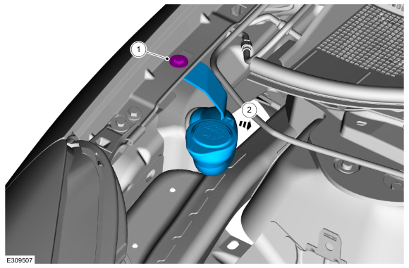
    C494-1 (component side) C495-4 (male side)

Is the resistance less than 3 ohms?
Yes GO to AT7
No VERIFY the high current fuse box fuse 4 (300A) is OK
REFER to: High Voltage Battery - Plug-In Hybrid Electric Vehicle (PHEV) (414-03A High Voltage Battery, Mounting and Cables, Removal and Installation).
If OK, REPAIR circuit. If not OK, REFER to the Wiring Diagrams manual to identify the possible causes of the circuit resistance. INSTALL new high voltage cables from the Secondary Inverter System Controller (S-ISC) to the traction battery, if necessary. REFER to: High Voltage Battery Cables - Plug-In Hybrid Electric Vehicle (PHEV) (414-03A High Voltage Battery, Mounting and Cables, Removal and Installation). CLEAR the Secondary Inverter System Controller (S-ISC) DTC s. REPEAT the self-test.

AT7 VERIFY THAT THE CONCERN IS PRESENT

NOTE: Clearing the Secondary Inverter System Controller (S-ISC) Diagnostic Trouble Codes (DTCs) will erase any Secondary Inverter System Controller (S-ISC) recorded freeze frame data. Make sure to record any Secondary Inverter System Controller (S-ISC) freeze frame information before proceeding any further. Refer to the scan tool instruction manual for freeze frame Parameter Identification (PID) menu.

  • Inspect the High Voltage Battery Junction Box C494 and C495 connectors for damaged or pushed-out pins.
  • Inspect the Secondary Inverter System Controller (S-ISC) C4210A connector for damaged or pushed-out pins.
  • Repair:
    • corrosion (install new connector or terminals – clean module pins)
    • damaged or bent pins – install new terminals/pins
    • pushed-out pins – install new pins as necessary
  • Connect High Voltage Battery Junction Box C494 .
  • Connect High Voltage Battery Junction Box C495 .
  • Connect Secondary Inverter System Controller (S-ISC) C4210A .
  • Verify the connectors seat and latch correctly.
  • Repower the high voltage system.
    REFER to: High Voltage System De-energizing (414-03A High Voltage Battery, Mounting and Cables, General Procedures).
  • Ignition ON.
  • CLEAR the Secondary Inverter System Controller (S-ISC) DTC s.
  • CARRY out the Secondary Inverter System Controller (S-ISC) self-test.

Is DTC P0DA8 present?
Yes REPLACE the high voltage harness between the Secondary Inverter System Controller (S-ISC) and battery.
REFER to: High Voltage Battery Cables - Plug-In Hybrid Electric Vehicle (PHEV) (414-03A High Voltage Battery, Mounting and Cables, Removal and Installation).
No GO to AT8

AT8 CHECK THE HIGH VOLTAGE CABLES FOR AN INTERMITTENT CONCERN
  • Ignition ON.
  • Access the  SOBDMB  and monitor the  GEN_INV_V (V)  PID

  • Carefully wiggle all accessible wiring and connectors associated with the High Voltage Cable from the Secondary Inverter System Controller (S-ISC) to the Traction Battery, and look for a change in the PID state.

Does the voltage vary by more than 10 volts during the wiggle test or by more than 30 volts during the drive cycle test?
Yes REPLACE the high voltage harness between the Secondary Inverter System Controller (S-ISC) and battery.
REFER to: High Voltage Battery Cables - Plug-In Hybrid Electric Vehicle (PHEV) (414-03A High Voltage Battery, Mounting and Cables, Removal and Installation).
No The system is operating correctly at this time. The concern may have been caused by a loose or corroded connector.

PINPOINT TEST AU: P0DFA

NOTE: The Secondary Inverter System Controller (S-ISC) is referred to as the SOBDMB (Secondary On-Board Diagnostic Control Module B) in the scan tool.

Normal Operation and Fault Conditions

REFER to: Rear Electric Drive Assembly - System Operation and Component Description (302-02 Rear Electric Drive Assembly, Description and Operation).

DTC Fault Trigger Conditions

DTC Description Fault Trigger Condition
SOBDMB P0DFA:00 Generator Phase U-V-W Current Sensor Correlation: No Sub Type Information This DTC sets when a generator phase current checksum error is detected.

Possible Sources

  • Other Secondary Inverter System Controller (S-ISC) DTC s
  • Rear (secondary) electric drive assembly
  • Secondary Inverter System Controller (S-ISC)
AU1 PERFORM THE SECONDARY INVERTER SYSTEM CONTROLLER (S-ISC) SELF-TEST
  • Using a diagnostic scan tool, perform the Secondary Inverter System Controller (S-ISC) self-test.

Are any Secondary Inverter System Controller (S-ISC) DTC s other than P0DFA present?
Yes DIAGNOSE all other Secondary Inverter System Controller (S-ISC) DTC s, REFER to the DTC chart in this section.
No GO to AU2

AU2 CHECK THE SECONDARY INVERTER SYSTEM CONTROLLER (S-ISC) CALIBRATION LEVEL
  • Verify the Secondary Inverter System Controller (S-ISC) is at the latest calibration level.

Is the Secondary Inverter System Controller (S-ISC) at the latest calibration level?
Yes GO to AU3
No UPDATE the Secondary Inverter System Controller (S-ISC) to the latest calibration level. CLEAR the DTC s and REPEAT the self-test.

AU3 VISUAL INSPECTION OF THE HIGH VOLTAGE SYSTEM
  • Ignition OFF.
  • Depower the high voltage battery.
    REFER to: High Voltage System De-energizing (414-03A High Voltage Battery, Mounting and Cables, General Procedures).
  • Visually inspect all the high voltage cables.
  • Make sure all the high voltage connectors are correctly and securely connected.
  • Examine all the high voltage connections for damage and loose or broken conditions.

Is a concern present?
Yes REPAIR as necessary. CLEAR the Secondary Inverter System Controller (S-ISC) DTC s and REPEAT the self-test.
No GO to AU4

AU4 CHECK THE ELECTRIC GENERATOR CIRCUITS FOR AN OPEN
  • Disconnect Rear (secondary) electric drive assembly C4048 .
  • Disconnect Secondary Inverter System Controller (S-ISC) C4210B .
  • Measure and record:
    Click to display connectors
    Positive Lead Measurement / Action Negative Lead
      C4210B-1   C4048-1
      C4210B-2   C4048-2
      C4210B-3   C4048-3

Are the resistances less than 5 ohms?
Yes GO to AU5
No INSTALL new high voltage cables.
REFER to: High Voltage Battery Cables - Plug-In Hybrid Electric Vehicle (PHEV) (414-03A High Voltage Battery, Mounting and Cables, Removal and Installation). CLEAR the DTC s and REPEAT the self-test.

AU5 CHECK THE ELECTRIC GENERATOR CIRCUITS FOR A SHORT TO THE EXTERNAL CABLE SHIELD
  • Measure and record:
    Click to display connectors
    Positive Lead Measurement / Action Negative Lead
      C4210B-1 C4210, external cable shield
      C4210B-2 C4210, external cable shield
      C4210B-3 C4210, external cable shield

Are the resistances greater than 10K ohms?
Yes GO to AU6
No INSTALL new high voltage cables.
REFER to: High Voltage Battery Cables - Plug-In Hybrid Electric Vehicle (PHEV) (414-03A High Voltage Battery, Mounting and Cables, Removal and Installation). CLEAR the DTC s and REPEAT the self-test.

AU6 CHECK THE ELECTRIC GENERATOR CIRCUITS FOR A SHORT TO GROUND
  • Measure and record:
    Click to display connectors
    Positive Lead Measurement / Action Negative Lead
      C4210B-1   Ground
      C4210B-2   Ground
      C4210B-3   Ground

Are the resistances greater than 10K ohms?
Yes GO to AU7
No INSTALL new high voltage cables.
REFER to: High Voltage Battery Cables - Plug-In Hybrid Electric Vehicle (PHEV) (414-03A High Voltage Battery, Mounting and Cables, Removal and Installation). CLEAR the DTC s and REPEAT the self-test.

AU7 CHECK THE ELECTRIC GENERATOR CIRCUITS FOR A SHORT TOGETHER
  • Measure and record:
    Click to display connectors
    Positive Lead Measurement / Action Negative Lead
      C4210B-1   C4210B-2
      C4210B-1   C4210B-3
      C4210B-3   C4210B-2

Are the resistances greater than 10K ohms?
Yes GO to AU8
No INSTALL new high voltage cables.
REFER to: High Voltage Battery Cables - Plug-In Hybrid Electric Vehicle (PHEV) (414-03A High Voltage Battery, Mounting and Cables, Removal and Installation). CLEAR the DTC s and REPEAT the self-test.

AU8 CHECK THE ELECTRIC GENERATOR FOR CONTINUITY
  • Measure and record:
    Click to display connectors
    Positive Lead Measurement / Action Negative Lead
    C4048 pin 1, component side C4048 pin 2, component side
    C4048 pin 1, component side C4048 pin 3, component side
    C4048 pin 2, component side C4048 pin 3, component side

Are the resistances less than 5 ohms?
Yes GO to AU9
No INSTALL a new rear (secondary) electric drive assembly.
REFER to: Rear Electric Drive Assembly (302-02 Rear Electric Drive Assembly, Removal and Installation). CLEAR the Secondary Inverter System Controller (S-ISC) DTC s. REPEAT the self-test.

AU9 CHECK THE ELECTRIC GENERATOR FOR A SHORT TO GROUND
  • Measure and record:
    Click to display connectors
    Positive Lead Measurement / Action Negative Lead
    C4048 pin 1, component side   Ground
    C4048 pin 2, component side   Ground
    C4048 pin 3, component side   Ground

Are the resistances greater than 10K ohms?
Yes GO to AU10
No INSTALL a new rear (secondary) electric drive assembly.
REFER to: Rear Electric Drive Assembly (302-02 Rear Electric Drive Assembly, Removal and Installation). CLEAR the Secondary Inverter System Controller (S-ISC) DTC s. REPEAT the self-test.

AU10 RECHECK THE SECONDARY INVERTER SYSTEM CONTROLLER (S-ISC) DIAGNOSTIC TROUBLE CODES (DTCS)
  • Reconnect all previously disconnected connectors.
  • Repower the high voltage battery,
    REFER to: High Voltage System De-energizing (414-03A High Voltage Battery, Mounting and Cables, General Procedures).
  • Ignition ON.
  • Using a diagnostic scan tool, clear the Secondary Inverter System Controller (S-ISC) DTC s.
  • Ignition OFF.
  • Ignition ON.
  • Wait 10 seconds.
  • Using a diagnostic scan tool, retrieve the Secondary Inverter System Controller (S-ISC) CMDTC s.

Is DTC P0DFA the only DTC present?
Yes CHECK OASIS for any applicable service articles: TSB , GSB , SSM or FSA . If a service article exists for this concern, DISCONTINUE this test and FOLLOW the service article instructions. If no service articles address this concern, INSTALL a new Secondary Inverter System Controller (S-ISC).
REFER to: Inverter System Controller [SOBDMB] (302-02 Rear Electric Drive Assembly, Removal and Installation).
No The system is operating correctly at this time. The DTC may have set due to high network traffic or an intermittent fault condition. CLEAR the Secondary Inverter System Controller (S-ISC) DTC s and REPEAT the self-test.

PINPOINT TEST AV: P0DFC

NOTE: The Secondary Inverter System Controller (S-ISC) is referred to as the SOBDMB (Secondary On-Board Diagnostic Control Module B) in the scan tool.

Normal Operation and Fault Conditions

REFER to: Rear Electric Drive Assembly - System Operation and Component Description (302-02 Rear Electric Drive Assembly, Description and Operation).

DTC Fault Trigger Conditions

DTC Description Fault Trigger Condition
SOBDMB P0DFC:00 Generator Position Sensor Not Learned: No Sub Type Information This DTC sets if the SEDID block is programmed, but the data is determined to be out of range.

Possible Sources

  • SEDID block programming
  • Secondary Inverter System Controller (S-ISC) calibration
AV1 VERIFY THE SECONDARY INVERTER SYSTEM CONTROLLER (S-ISC) CALIBRATION LEVEL
  • Verify the Secondary Inverter System Controller (S-ISC) is at the latest calibration level.

Is the Secondary Inverter System Controller (S-ISC) at the latest calibration level?
Yes GO to AV2
No UPDATE the Secondary Inverter System Controller (S-ISC) to the latest calibration level.

AV2 VERIFY THE SECONDARY INVERTER SYSTEM CONTROLLER (S-ISC) SEDID BLOCK HAS BEEN PROGRAMMED CORRECTLY

NOTE: To avoid confusion the TRID information corresponds with the primary (front) electric drive system and is stored in the primary ISC (SOBDM-C). The SEDID stores similar but different information which corresponds with the secondary (rear) electric drive system and is stored in the S-ISC (SOBDM-B).

  • Verify the Secondary Inverter System Controller (S-ISC) SEDID block has been programmed correctly. Refer to Module Reprogramming on the scan tool.

Has the SEDID block been successfully programmed?
Yes GO to AV3
No CHECK OASIS for any applicable service articles: TSB , GSB , SSM or FSA . If a service article exists for this concern, DISCONTINUE this test and FOLLOW the service article instructions. If no service articles address this concern, reflash the Secondary Inverter System Controller (S-ISC) SEDID block.

AV3 REPEAT THE SELF-TEST
  • CLEAR the Secondary Inverter System Controller (S-ISC) DTC s.
  • CARRY out the Secondary Inverter System Controller (S-ISC) self-test.

Is DTC P0DFC present?
Yes CHECK OASIS for any applicable service articles: TSB , GSB , SSM or FSA . If a service article exists for this concern, DISCONTINUE this test and FOLLOW the service article instructions. If no service articles address this concern, reflash the Secondary Inverter System Controller (S-ISC) SEDID block. If the concern is still present after the SEDID block flash, it is necessary to seek additional help. REFER to the Service Repair And Technical Assistance Process.
No The system is operating correctly at this time. The DTC may have been set due to high network traffic or an intermittent fault condition, the SEDID block was not programmed correctly or was erased.

PINPOINT TEST AW: P0E71

NOTE: The Secondary Inverter System Controller (S-ISC) is referred to as the SOBDMB (Secondary On-Board Diagnostic Control Module B) in the scan tool.

Normal Operation and Fault Conditions

REFER to: Rear Electric Drive Assembly - System Operation and Component Description (302-02 Rear Electric Drive Assembly, Description and Operation).

DTC Fault Trigger Conditions

DTC Description Fault Trigger Condition
SOBDMB P0E71:00 Generator Torque Delivered Performance: No Sub Type Information This DTC sets if the generator system is temporarily disabled and is a notification of other faults in the system.

Possible Sources

  • Other related DTC s within the Secondary Inverter System Controller (S-ISC)
  • Wiring, terminals or connectors
AW1 CHECK FOR SECONDARY INVERTER SYSTEM CONTROLLER (S-ISC) DIAGNOSTIC TROUBLE CODES (DTCS)
  • Using a diagnostic scan tool, perform the Secondary Inverter System Controller (S-ISC) self-test.

Is P0E71:00 the only DTC present?
Yes GO to AW2
No DIAGNOSE all other Secondary Inverter System Controller (S-ISC) DTC s, REFER to the DTC chart in this section.

AW2 CHECK THE SECONDARY INVERTER SYSTEM CONTROLLER (S-ISC) CALIBRATION LEVEL
  • Verify the Secondary Inverter System Controller (S-ISC) is at the latest calibration level.

Is the Secondary Inverter System Controller (S-ISC) at the latest calibration level?
Yes The system is operating correctly at this time. The DTC may have been set due to high network traffic or an intermittent fault condition.
No UPDATE the Secondary Inverter System Controller (S-ISC) to the latest calibration level.

PINPOINT TEST AX: P174E

NOTE: The Secondary Inverter System Controller (S-ISC) is referred to as the SOBDMB (Secondary On-Board Diagnostic Control Module B) in the scan tool.

Normal Operation and Fault Conditions

REFER to: Rear Electric Drive Assembly - System Operation and Component Description (302-02 Rear Electric Drive Assembly, Description and Operation).

DTC Fault Trigger Conditions

DTC Description Fault Trigger Condition
SOBDMB P174E:00 Output Shaft Speed / ABS Wheel Speed Correlation: No Sub Type Information This DTC sets when the output shaft speed is different than the average wheel speeds reported by the ABS module.

Possible Sources

  • Broken or disconnected half shaft
  • Incorrect wheel speed values
AX1 INSPECT THE HALF SHAFTS
  • Ignition OFF.
  • Visually inspect all half shafts for damage.

Is a concern present?
Yes REPAIR as necessary. CLEAR the Secondary Inverter System Controller (S-ISC) DTC s and REPEAT the self-test.
No GO to AX2

AX2 CHECK FOR ABS (ANTI-LOCK BRAKE SYSTEM) DIAGNOSTIC TROUBLE CODES (DTCS)
  • Using a diagnostic scan tool, perform the ABS module self-test.

Are any ABS DTC s present?
Yes DIAGNOSE all other ABS DTC s.
No DIAGNOSE the observable symptom. REFER to
REFER to: Anti-Lock Brake System (ABS) and Stability Control (206-09 Anti-Lock Brake System (ABS) and Stability Control, Diagnosis and Testing).

PINPOINT TEST AY: P1A0E:61, P1A0E:62, P1A0E:64, P1A0E:96

NOTE: The Secondary Inverter System Controller (S-ISC) is referred to as the SOBDMB in the scan tool.

Normal Operation and Fault Conditions

REFER to: Rear Electric Drive Assembly - System Operation and Component Description (302-02 Rear Electric Drive Assembly, Description and Operation).

DTC Fault Trigger Conditions

DTC Description Fault Trigger Condition
SOBDMB P1A0E:61 Hybrid Powertrain Control Module - Motor Disabled: Signal Calculation Failure This DTC sets when the motor torque is out of a calculated range.
SOBDMB P1A0E:62 Hybrid Powertrain Control Module - Motor Disabled: Signal Compare Failure This DTC sets when the motor torque is out of range.
SOBDMB P1A0E:64 Hybrid Powertrain Control Module - Motor Disabled: Signal Plausibility Failure This DTC sets when a plausibility fault with motor torque is detected.
SOBDMB P1A0E:96 Hybrid Powertrain Control Module - Motor Disabled: Component Internal Failure This DTC sets when a motor phase current checksum error is detected.

Possible Sources

  • Other Secondary Inverter System Controller (S-ISC) DTC s
  • Rear (secondary) electric drive assembly
  • Secondary Inverter System Controller (S-ISC)
AY1 CHECK FOR SECONDARY INVERTER SYSTEM CONTROLLER (S-ISC) DIAGNOSTIC TROUBLE CODES (DTCS)
  • Ignition ON.
  • Using a diagnostic scan tool, perform the Secondary Inverter System Controller (S-ISC) self-test.

Are any Secondary Inverter System Controller (S-ISC) DTC s other than P1A0E:61, P1A0E:62, P1A0E:64 or P1A0E:96 present?
Yes DIAGNOSE all other Secondary Inverter System Controller (S-ISC) DTC s, REFER to the DTC chart in this section.
No GO to AY2

AY2 CHECK THE SECONDARY INVERTER SYSTEM CONTROLLER (S-ISC) CALIBRATION LEVEL
  • Verify the Secondary Inverter System Controller (S-ISC) is at the latest calibration level.

Is the Secondary Inverter System Controller (S-ISC) at the latest calibration level?
Yes GO to AY3
No UPDATE the Secondary Inverter System Controller (S-ISC) to the latest calibration level.

AY3 VISUAL INSPECTION OF THE HIGH VOLTAGE SYSTEM
  • Ignition OFF.
  • Depower the high voltage system.
    REFER to: High Voltage System De-energizing (414-03A High Voltage Battery, Mounting and Cables, General Procedures).
  • Disconnect Secondary Inverter System Controller (S-ISC) C4210A and C4210B .
  • Disconnect Rear (secondary) electric drive assembly C4048 .
  • Examine all the high voltage connections for damage and loose or broken conditions.

Is a concern present?
Yes REPAIR as necessary. CLEAR the Secondary Inverter System Controller (S-ISC) DTC s and REPEAT the self-test.
No GO to AY4

AY4 CHECK THE REAR ELECTRIC DRIVE ASSEMBLY FOR CONTINUITY
  • Measure and record:
    Click to display connectors
    Positive Lead Measurement / Action Negative Lead
    C4048 pin 1, component side C4048 pin 2, component side
    C4048 pin 1, component side C4048 pin 3, component side
    C4048 pin 2, component side C4048 pin 3, component side

Are the resistances less than 5 ohms?
Yes GO to AY5
No INSTALL a new rear (secondary) electric drive assembly (NOTE: this does not and should not include a new Secondary Inverter System Controller (S-ISC)/SOBDMB ).
REFER to: Rear Electric Drive Assembly (302-02 Rear Electric Drive Assembly, Removal and Installation). CLEAR the Secondary Inverter System Controller (S-ISC) DTC s. REPEAT the self-test.

AY5 CHECK THE REAR ELECTRIC DRIVE ASSEMBLY FOR A SHORT TO GROUND
  • Measure and record:
    Positive Lead Measurement / Action Negative Lead
    C4048 pin 1, component side   Ground
    C4048 pin 2, component side   Ground
    C4048 pin 3, component side   Ground

Is the resistance greater than 10K ohms?
Yes GO to AY6
No INSTALL a new rear (secondary) electric drive assembly (NOTE: this does not and should not include a new Secondary Inverter System Controller (S-ISC)/SOBDMB ).
REFER to: Rear Electric Drive Assembly (302-02 Rear Electric Drive Assembly, Removal and Installation). CLEAR the Secondary Inverter System Controller (S-ISC) DTC s. REPEAT the self-test.

AY6 RECHECK THE SECONDARY INVERTER SYSTEM CONTROLLER (S-ISC) DIAGNOSTIC TROUBLE CODES (DTCS)
  • Repower the high voltage system.
    REFER to: High Voltage System De-energizing (414-03A High Voltage Battery, Mounting and Cables, General Procedures).
  • Ignition ON.
  • Using a diagnostic scan tool, clear the Secondary Inverter System Controller (S-ISC) DTC s.
  • Ignition OFF.
  • Ignition ON.
  • Wait 10 seconds.
  • Using a diagnostic scan tool, perform the continuous memory self-test.
  • Check the Secondary Inverter System Controller (S-ISC) DTC s.

Are DTC s P1A0E:61, P1A0E:62, P1A0E:64 or P1A0E:96 the only DTC s present?
Yes CHECK OASIS for any applicable service articles: TSB , GSB , SSM or FSA . If a service article exists for this concern, DISCONTINUE this test and FOLLOW the service article instructions. If no service articles address this concern, INSTALL a new Secondary Inverter System Controller (S-ISC).
REFER to: Inverter System Controller [SOBDMB] (302-02 Rear Electric Drive Assembly, Removal and Installation).
No The system is operating correctly at this time. The DTC may have set due to high network traffic or an intermittent fault condition. CLEAR the Secondary Inverter System Controller (S-ISC) DTC s and REPEAT the self-test.

PINPOINT TEST AZ: P1A07

NOTE: The Secondary Inverter System Controller (S-ISC) is referred to as the SOBDMB (Secondary On-Board Diagnostic Control Module B) in the scan tool.

Normal Operation and Fault Conditions

REFER to: Rear Electric Drive Assembly - System Operation and Component Description (302-02 Rear Electric Drive Assembly, Description and Operation).

DTC Fault Trigger Conditions

DTC Description Fault Trigger Condition
SOBDMB P1A07:00 Inverter High Voltage Performance: No Sub Type Information This DTC sets when the powertrain is trying to protect the battery hardware from extreme voltage (high or low).

Possible Sources

  • Depleted high voltage battery
  • High voltage battery fuse
  • High voltage battery system DTC s
  • High voltage cable connections
AZ1 VISUAL INSPECTION OF THE HIGH VOLTAGE SYSTEM
  • Ignition OFF.
  • Depower the high voltage system.
    REFER to: High Voltage System De-energizing (414-03A High Voltage Battery, Mounting and Cables, General Procedures).
  • Visually inspect all the high voltage cables.
  • Make sure all the high voltage connectors are correctly and securely connected.
  • Examine all the high voltage connections for damage and loose or broken conditions.

Is a concern present?
Yes REPAIR as necessary. CLEAR the Secondary Inverter System Controller (S-ISC) DTC s and REPEAT the self-test.
No GO to AZ2

AZ2 VERIFY THE HIGH VOLTAGE TRACTION BATTERY STATE OF CHARGE
  • Connect all previously disconnected connectors.
  • Re-energize the high voltage system.
    REFER to: High Voltage System De-energizing (414-03A High Voltage Battery, Mounting and Cables, General Procedures).
  • Ignition ON.
  • Access the  SOBDMB  and monitor the  HVBAT_V (V)  PID


Is the voltage greater than 168 volts?
Yes GO to AZ3
No CHARGE the high voltage traction battery.
REFER to: High Voltage Battery, Mounting and Cables - Plug-In Hybrid Electric Vehicle (PHEV) - Overview (414-03A High Voltage Battery, Mounting and Cables, Description and Operation). CLEAR the Secondary Inverter System Controller (S-ISC) DTC s. REPEAT the self-test.

AZ3 VERIFY CONCERN IS PRESENT

NOTE: Clearing the Secondary Inverter System Controller (S-ISC) Diagnostic Trouble Codes (DTCs) will erase any Secondary Inverter System Controller (S-ISC) recorded freeze frame data. Make sure to record any Secondary Inverter System Controller (S-ISC) freeze frame information before proceeding any further. Refer to the scan tool instruction manual for freeze frame Parameter Identification (PID) menu.

  • CLEAR the Secondary Inverter System Controller (S-ISC) DTC s.
  • CARRY out the Secondary Inverter System Controller (S-ISC) self-test.

Is DTC P1A07 present?
Yes GO to AZ4
No GO to AZ7

AZ4 CHECK THE HIGH VOLTAGE POSITIVE CABLE FOR AN OPEN
  • Depower the high voltage system.
    REFER to: High Voltage System De-energizing (414-03A High Voltage Battery, Mounting and Cables, General Procedures).
  • Ignition OFF.
  • Disconnect High Voltage Battery Junction Box C494 .
  • Inspect the connector for damaged or pushed-out pins.
  • Disconnect Secondary Inverter System Controller (S-ISC) C4210A .
  • Inspect the connector for damaged or pushed-out pins.
  • Measure and record:
    Positive Lead Measurement / Action Negative Lead
      C494-1   C4210A-4

Is the resistance less than 5 ohms?
Yes GO to AZ5
No INSTALL a new High Voltage Cable from the Secondary Inverter System Controller (S-ISC) to the traction battery.
REFER to: High Voltage Battery Cables - Plug-In Hybrid Electric Vehicle (PHEV) (414-03A High Voltage Battery, Mounting and Cables, Removal and Installation).
CLEAR the Secondary Inverter System Controller (S-ISC) DTC s. REPEAT the self-test.

AZ5 CHECK THE HIGH VOLTAGE NEGATIVE CABLE FOR AN OPEN
  • Measure and record:
    Positive Lead Measurement / Action Negative Lead
      C494-4   C4210A-1

Is the resistance less than 5 ohms?
Yes GO to AZ6
No INSTALL a new High Voltage Cable from the Secondary Inverter System Controller (S-ISC) to the traction battery.
REFER to: High Voltage Battery Cables - Plug-In Hybrid Electric Vehicle (PHEV) (414-03A High Voltage Battery, Mounting and Cables, Removal and Installation).
CLEAR the Secondary Inverter System Controller (S-ISC) DTC s. REPEAT the self-test.

AZ6 CHECK THE HIGH VOLTAGE CABLES FOR A SHORT FROM POSTIVE TO NEGATIVE
  • Ignition OFF.
  • Measure and record:
    Positive Lead Measurement / Action Negative Lead
      C494-4   C494-1

Is the resistance below 10K ohms?
Yes INSTALL new high voltage cables.
REFER to: High Voltage Battery Cables - Plug-In Hybrid Electric Vehicle (PHEV) (414-03A High Voltage Battery, Mounting and Cables, Removal and Installation).
CLEAR the Secondary Inverter System Controller (S-ISC) DTC s and REPEAT the self-test.
No GO to AZ7

AZ7 CHECK THE HIGH VOLTAGE CABLES FOR AN INTERMITTENT CONCERN
  • Ignition OFF.
  • De-energize the high voltage system.
    REFER to: High Voltage System De-energizing (414-03A High Voltage Battery, Mounting and Cables, General Procedures).
  • Disconnect and inspect all the High Voltage Battery Junction Box connectors.
  • Disconnect and inspect all the Secondary Inverter System Controller (S-ISC) connectors.
  • Repair:
    • corrosion (install new connector or terminals – clean module pins)
    • damaged or bent pins – install new terminals/pins
    • pushed-out pins – install new pins as necessary
  • Reconnect the High Voltage Battery Junction Box connectors. Make sure they seat and latch correctly.
  • Reconnect the Secondary Inverter System Controller (S-ISC) connectors. Make sure they seat and latch correctly.
  • Re-energize the high voltage system.
    REFER to: High Voltage System De-energizing (414-03A High Voltage Battery, Mounting and Cables, General Procedures).
  • Ignition ON.
  • Access the  SOBDMB  and monitor the  GEN_INV_V (V)  PID

  • Carefully wiggle all accessible wiring and connectors associated with the High Voltage Cable from the Secondary Inverter System Controller (S-ISC) to the Traction Battery, and look for a change in the PID state.

Is a concern present during the wiggle test?
Yes REPAIR as necessary.
No The system is operating correctly at this time. The DTC may have been set due to high network traffic or an intermittent fault condition.

PINPOINT TEST BA: P1A0A:02

NOTE: The Secondary Inverter System Controller (S-ISC) is referred to as the SOBDMB (Secondary On-Board Diagnostic Control Module B) in the scan tool.

Normal Operation and Fault Conditions

REFER to: Rear Electric Drive Assembly - System Operation and Component Description (302-02 Rear Electric Drive Assembly, Description and Operation).

DTC Fault Trigger Conditions

DTC Description Fault Trigger Condition
SOBDMB P1A0A:02 Immediate Shutdown Signal A: General Signal Failure This DTC sets when the Secondary Inverter System Controller (S-ISC) is commanded to shut down from the BECM or the RCM

Possible Sources

  • High voltage battery DTC s
  • RCM diagnostic trouble codes (DTCs)
BA1 VERIFY THE SECONDARY INVERTER SYSTEM CONTROLLER (S-ISC) SHUTDOWN REQUEST
  • Confirm the vehicle was not in an accident.

Was the vehicle involved in a collision?
Yes REPAIR any damage to the vehicle. CLEAR the Secondary Inverter System Controller (S-ISC) DTC s.
No GO to BA2

BA2 CHECK THE BECM (BATTERY ENERGY CONTROL MODULE) DIAGNOSTIC TROUBLE CODES (DTCS)
  • Using a diagnostic scan tool, run the BECM self-tests.

Are there any BECM DTC s?
Yes DIAGNOSE and REPAIR any BECM DTC s.
REFER to: High Voltage Battery, Mounting and Cables - Plug-In Hybrid Electric Vehicle (PHEV) (414-03A High Voltage Battery, Mounting and Cables, Diagnosis and Testing).
No GO to BA3

BA3 CHECK THE RCM (RESTRAINTS CONTROL MODULE) DIAGNOSTIC TROUBLE CODES (DTCS)
  • Using a diagnostic scan tool, run the RCM self-tests.

Are there any RCM DTC s?
Yes DIAGNOSE and REPAIR any RCM .
REFER to: Airbag Supplemental Restraint System (SRS) (501-20B Supplemental Restraint System, Diagnosis and Testing).
No The system is operating correctly at this time. The DTC may have been set due to high network traffic or an intermittent fault condition.

PINPOINT TEST BB: U0100

NOTE: The Secondary Inverter System Controller (S-ISC) is referred to as the SOBDMB (Secondary On-Board Diagnostic Control Module B) in the scan tool.

Normal Operation and Fault Conditions

REFER to: Rear Electric Drive Assembly - System Operation and Component Description (302-02 Rear Electric Drive Assembly, Description and Operation).

DTC Fault Trigger Conditions

DTC Description Fault Trigger Condition
SOBDMB U0100:00 Lost Communication With ECM/PCM 'A': No Sub Type Information This DTC sets when messages are missing from the ECM .

Possible Sources

  • Communications network concern
  • ECM
BB1 VERIFY THE CONCERN
  • Ignition ON.
  • Verify an observable symptom present.

Is an observable symptom present?
Yes GO to BB2
No The system is operating normally at this time. The DTC may have been set due to high network traffic or an intermittent fault condition.

BB2 VERIFY THE DIAGNOSTIC SCAN TOOL COMMUNICATES WITH THE ECM (ENGINE CONTROL MODULE)
  • Connect the diagnostic scan tool to the vehicle.
  • Attempt to establish a vehicle session using the diagnostic scan tool.

Can a vehicle session be established?
Yes GO to BB3
No
REFER to: Communications Network (418-00 Module Communications Network, Diagnosis and Testing).

BB3 CHECK FOR NON-NETWORK DIAGNOSTIC TROUBLE CODES (DTCS)
  • Using a diagnostic scan tool, carry out the Secondary Inverter System Controller (S-ISC) self-test.

Are any non-network DTC s present?
Yes DIAGNOSE all non-network DTC s first. REFER to the appropriate DTC Chart in this section.
No GO to BB4

BB4 CHECK FOR ECM (ENGINE CONTROL MODULE) DIAGNOSTIC TROUBLE CODES (DTCS)
  • Using a diagnostic scan tool, carry out the ECM self-test.

Are any non-network DTC s present?
Yes REFER to Diagnosis and Testing in the appropriate 303-14 section.
No GO to BB5

BB5 CHECK THE SECONDARY INVERTER SYSTEM CONTROLLER (S-ISC) AND ECM (ENGINE CONTROL MODULE) CALIBRATION LEVELS
  • Verify the Secondary Inverter System Controller (S-ISC) and the ECM are at the latest calibration levels.

Are the Secondary Inverter System Controller (S-ISC) and the ECM at the latest calibration levels?
Yes GO to BB6
No UPDATE the Secondary Inverter System Controller (S-ISC) or ECM to the latest calibration level.

BB6 RECHECK FOR DTC (DIAGNOSTIC TROUBLE CODE) U0100:00
  • Using a diagnostic scan tool, clear the Secondary Inverter System Controller (S-ISC) DTC s.
  • Ignition OFF.
  • Ignition ON.
  • Wait 10 seconds.
  • Using a diagnostic scan tool, carry out the self-test for the Secondary Inverter System Controller (S-ISC).

Is DTC U0100:00 still present?
Yes GO to BB7
No The system is operating correctly at this time. The DTC may have set due to high network traffic or an intermittent fault condition.

BB7 CHECK FOR OTHER CAUSES OF NETWORK COMMUNICATION CONCERN

NOTE: If new modules were installed prior to the DTC being set, the module configuration can be incorrectly set during the PMI or the PMI may not have been carried out.

  • Check the vehicle service history for recent service actions related to the ECM and the Secondary Inverter System Controller (S-ISC). If recent service history is found:
    • verify correct replacement module was installed
      • vehicle parts build list may be used to verify correct part fitment
    • verify the configuration of replacement module was correct
      • re-configure module using as-built data if prior configuration is suspect
    • verify the module was not obtained from a like vehicle and installed into vehicle with concern
      • return the swapped module to source vehicle and obtain new replacement module
  • Operate the system and determine if the observable symptom is still present.

Is the observable symptom still present?
Yes GO to BB8
No The system is operating correctly at this time. The concern may have been due to incorrect parts replacement procedures or incorrect module configuration.

BB8 CHECK FOR CORRECT ECM (ENGINE CONTROL MODULE) OPERATION
  • Ignition OFF.
  • Disconnect and inspect all the ECM connectors.
  • Repair:
    • corrosion (install new connectors or terminals - clean module pins)
    • damaged or bent pins - install new terminals pins
    • pushed-out pins - install new pins as necessary
  • Reconnect the ECM connectors. Make sure they seat and latch correctly.
  • Operate the system and determine if the concern is still present.

Is the concern still present?
Yes CHECK OASIS for any applicable service articles: TSB , GSB , SSM or FSA . If a service article exists for this concern, DISCONTINUE this test and FOLLOW the service article instructions. If no service articles address this concern,
REFER to: Communications Network (418-00 Module Communications Network, Diagnosis and Testing).
No The system is operating correctly at this time. The concern may have been caused by module connections. ADDRESS the root cause of any connector or pin issues.

PINPOINT TEST BC: U0111

NOTE: The Secondary Inverter System Controller (S-ISC) is referred to as the SOBDMB (Secondary On-Board Diagnostic Control Module B) in the scan tool.

Normal Operation and Fault Conditions

REFER to: Rear Electric Drive Assembly - System Operation and Component Description (302-02 Rear Electric Drive Assembly, Description and Operation).

DTC Fault Trigger Conditions

DTC Description Fault Trigger Condition
SOBDMB U0111:00 Lost Communication With Battery Energy Control Module 'A': No Sub Type Information This DTC sets when messages are missing from the BECM .

Possible Sources

  • Communication concern
  • BECM
BC1 VERIFY THE CONCERN
  • Ignition ON.
  • Verify an observable symptom present.

Is an observable symptom present?
Yes GO to BC2
No The system is operating normally at this time. The DTC may have been set due to high network traffic or an intermittent fault condition.

BC2 VERIFY THE DIAGNOSTIC SCAN TOOL COMMUNICATES WITH THE BECM (BATTERY ENERGY CONTROL MODULE)
  • Connect the diagnostic scan tool to the vehicle.
  • Attempt to establish a vehicle session using the diagnostic scan tool.

Can a vehicle session be established?
Yes GO to BC3
No
REFER to: Communications Network (418-00 Module Communications Network, Diagnosis and Testing).

BC3 CHECK FOR NON-NETWORK DIAGNOSTIC TROUBLE CODES (DTCS)
  • Using a diagnostic scan tool, carry out the Secondary Inverter System Controller (S-ISC) self-test.

Are any non-network DTC s present?
Yes DIAGNOSE all non-network DTC s first. REFER to the appropriate DTC Chart in this section.
No GO to BC4

BC4 CHECK FOR BECM (BATTERY ENERGY CONTROL MODULE) DIAGNOSTIC TROUBLE CODES (DTCS)
  • Using a diagnostic scan tool, carry out the BECM self-test.

Are any non-network DTC s present?
Yes REFER to Diagnosis and Testing in the appropriate 414-03 section.
No GO to BC5

BC5 CHECK THE SECONDARY INVERTER SYSTEM CONTROLLER (S-ISC) AND BECM (BATTERY ENERGY CONTROL MODULE) CALIBRATION LEVELS
  • Verify the Secondary Inverter System Controller (S-ISC) and the BECM are at the latest calibration levels.

Are the Secondary Inverter System Controller (S-ISC) and the BECM at the latest calibration levels?
Yes GO to BC6
No UPDATE the Secondary Inverter System Controller (S-ISC) or BECM to the latest calibration level.

BC6 RECHECK FOR DTC (DIAGNOSTIC TROUBLE CODE) U0111
  • Using a diagnostic scan tool, clear the Secondary Inverter System Controller (S-ISC) DTC s.
  • Ignition OFF.
  • Ignition ON.
  • Wait 10 seconds.
  • Using a diagnostic scan tool, carry out the self-test for the Secondary Inverter System Controller (S-ISC).

Is DTC U0111 still present?
Yes GO to BC7
No The system is operating correctly at this time. The DTC may have set due to high network traffic or an intermittent fault condition.

BC7 CHECK FOR OTHER CAUSES OF NETWORK COMMUNICATION CONCERN

NOTE: If new modules were installed prior to the DTC being set, the module configuration can be incorrectly set during the PMI or the PMI may not have been carried out.

  • Check the vehicle service history for recent service actions related to the BECM and the Secondary Inverter System Controller (S-ISC). If recent service history is found:
    • verify correct replacement module was installed
      • vehicle parts build list may be used to verify correct part fitment
    • verify the configuration of replacement module was correct
      • re-configure module using as-built data if prior configuration is suspect
    • verify the module was not obtained from a like vehicle and installed into vehicle with concern
      • return the swapped module to source vehicle and obtain new replacement module
  • Operate the system and determine if the observable symptom is still present.

Is the observable symptom still present?
Yes GO to BC8
No The system is operating correctly at this time. The concern may have been due to incorrect parts replacement procedures or incorrect module configuration.

BC8 CHECK FOR CORRECT BECM (BATTERY ENERGY CONTROL MODULE) OPERATION
  • Ignition OFF.
  • Disconnect and inspect all the BECM connectors.
  • Repair:
    • corrosion (install new connectors or terminals - clean module pins)
    • damaged or bent pins - install new terminals pins
    • pushed-out pins - install new pins as necessary
  • Reconnect the BECM connectors. Make sure they seat and latch correctly.
  • Operate the system and determine if the concern is still present.

Is the concern still present?
Yes CHECK OASIS for any applicable service articles: TSB , GSB , SSM or FSA . If a service article exists for this concern, DISCONTINUE this test and FOLLOW the service article instructions. If no service articles address this concern,
REFER to: Communications Network (418-00 Module Communications Network, Diagnosis and Testing).
No The system is operating correctly at this time. The concern may have been caused by module connections. ADDRESS the root cause of any connector or pin issues.

PINPOINT TEST BD: U0121

NOTE: The Secondary Inverter System Controller (S-ISC) is referred to as the SOBDMB (Secondary On-Board Diagnostic Control Module B) in the scan tool.

Normal Operation and Fault Conditions

REFER to: Rear Electric Drive Assembly - System Operation and Component Description (302-02 Rear Electric Drive Assembly, Description and Operation).

DTC Fault Trigger Conditions

DTC Description Fault Trigger Condition
SOBDMB U0121:00 Lost Communication With Anti-Lock Brake System (ABS) Control Module 'A': No Sub Type Information This DTC sets when messages are missing from the ABS module.

Possible Sources

  • Communications network concern
  • ABS module
BD1 VERIFY THE CONCERN
  • Ignition ON.
  • Verify there is an observable symptom present.

Is an observable symptom present?
Yes GO to BD2
No CLEAR the DTC . The system is operating correctly at this time. The DTC may have been set due to high network traffic or an intermittent fault condition.

BD2 VERIFY THE DIAGNOSTIC SCAN TOOL COMMUNICATES WITH THE ABS (ANTI-LOCK BRAKE SYSTEM) MODULE
  • Connect the diagnostic scan tool to the vehicle.
  • Attempt to establish a vehicle session using the diagnostic scan tool.

Can a vehicle session be established?
Yes GO to BD3
No
REFER to: Communications Network (418-00 Module Communications Network, Diagnosis and Testing).

BD3 CHECK FOR NON-NETWORK DIAGNOSTIC TROUBLE CODES (DTCS)
  • Using a diagnostic scan tool, carry out the Secondary Inverter System Controller (S-ISC) self-test.

Are any non-network DTC s present?
Yes DIAGNOSE all non-network DTC s first. REFER to the DTC Chart in this section.
No GO to BD4

BD4 CHECK FOR NON-NETWORK ABS (ANTI-LOCK BRAKE SYSTEM) MODULE DIAGNOSTIC TROUBLE CODES (DTCS)
  • Using a diagnostic scan tool, carry out the ABS module self-test.

Are any non-network DTC s present?
Yes REFER to Diagnosis and Testing in the appropriate 206-09 section.
No GO to BD5

BD5 CHECK THE SECONDARY INVERTER SYSTEM CONTROLLER (S-ISC) AND ABS (ANTI-LOCK BRAKE SYSTEM) MODULE CALIBRATION LEVELS
  • Verify the Secondary Inverter System Controller (S-ISC) and the ABS module are at the latest calibration levels.

Are the Secondary Inverter System Controller (S-ISC) and the ABS module at the latest calibration levels?
Yes GO to BD6
No UPDATE the Secondary Inverter System Controller (S-ISC) or ABS module to the latest calibration level.

BD6 RECHECK FOR DTC (DIAGNOSTIC TROUBLE CODE) U0121:00 AND U0121:8F
  • Using a diagnostic scan tool, clear the Secondary Inverter System Controller (S-ISC) DTC s.
  • Ignition OFF.
  • Ignition ON.
  • Wait 10 seconds.
  • Using a diagnostic scan tool, carry out the self-test for the Secondary Inverter System Controller (S-ISC).

Is DTC U0121:00 or U0121:8F still present?
Yes GO to BD7
No The system is operating correctly at this time. The DTC may have been set due to high network traffic or an intermittent fault condition.

BD7 CHECK FOR OTHER CAUSES OF NETWORK COMMUNICATION CONCERN

NOTE: If new modules were installed prior to the DTC being set, the module configuration can be incorrectly set during the PMI or the PMI may not have been carried out.

  • Check the vehicle service history for recent service actions related to the ABS module and the Secondary Inverter System Controller (S-ISC). If recent service history is found:
    • verify correct replacement module was installed
      • vehicle parts build list may be used to verify correct part fitment
    • verify the configuration of replacement module was correct
      • re-configure module using as-built data if prior configuration is suspect
    • verify the module was not obtained from a like vehicle and installed into vehicle with concern
      • return the swapped module to source vehicle and obtain new replacement module
  • Operate the system and determine if the observable symptom is still present.

Is the observable symptom still present?
Yes GO to BD8
No The system is operating correctly at this time. The concern may have been due to incorrect parts replacement procedures or incorrect module configuration.

BD8 CHECK FOR CORRECT ABS (ANTI-LOCK BRAKE SYSTEM) MODULE OPERATION
  • Ignition OFF.
  • Disconnect and inspect the ABS module connectors.
  • Repair:
    • corrosion (install new connectors or terminals - clean module pins)
    • damaged or bent pins - install new terminals pins
    • pushed-out pins - install new pins as necessary
  • Reconnect the ABS module connectors. Make sure they seat and latch correctly.
  • Operate the system and determine if the concern is still present.

Is the concern still present?
Yes CHECK OASIS for any applicable service articles: TSB , GSB , SSM or FSA . If a service article exists for this concern, DISCONTINUE this test and FOLLOW the service article instructions. If no service articles address this concern,
REFER to: Communications Network (418-00 Module Communications Network, Diagnosis and Testing).
No The system is operating correctly at this time. The concern may have been caused by module connections. ADDRESS the root cause of any connector or pin issues.

PINPOINT TEST BE: U0136

NOTE: The Secondary Inverter System Controller (S-ISC) is referred to as the SOBDMB (Secondary On-Board Diagnostic Control Module B) in the scan tool.

Normal Operation and Fault Conditions

REFER to: Rear Electric Drive Assembly - System Operation and Component Description (302-02 Rear Electric Drive Assembly, Description and Operation).

DTC Fault Trigger Conditions

DTC Description Fault Trigger Condition
PCM U0136:00 Lost Communication With Differential Control Module - Rear: No Sub Type Information This DTC sets when messages are missing from the Secondary Inverter System Controller (S-ISC) SOBDMB .
BECM U0136:00 Lost Communication With Differential Control Module - Rear: No Sub Type Information This DTC sets when messages are missing from the Secondary Inverter System Controller (S-ISC) SOBDMB .
IPC U0136:00 Lost Communication With Differential Control Module - Rear: No Sub Type Information This DTC sets when messages are missing from the Secondary Inverter System Controller (S-ISC) SOBDMB .
APIM U0136:00 Lost Communication With Differential Control Module - Rear: No Sub Type Information This DTC sets when messages are missing from the Secondary Inverter System Controller (S-ISC) SOBDMB .
PAM U0136:00 Lost Communication With Differential Control Module - Rear: No Sub Type Information This DTC sets when messages are missing from the Secondary Inverter System Controller (S-ISC) SOBDMB .
BCM U0136:00 Lost Communication With Differential Control Module - Rear: No Sub Type Information This DTC sets when messages are missing from the Secondary Inverter System Controller (S-ISC) SOBDMB .
BCMC U0136:00 Lost Communication With Differential Control Module - Rear: No Sub Type Information This DTC sets when messages are missing from the Secondary Inverter System Controller (S-ISC) SOBDMB .
DCDC U0136:00 Lost Communication With Differential Control Module - Rear: No Sub Type Information This DTC sets when messages are missing from the Secondary Inverter System Controller (S-ISC) SOBDMB .
SOBDMC U0136:00 Lost Communication With Differential Control Module - Rear: No Sub Type Information This DTC sets when messages are missing from the Secondary Inverter System Controller (S-ISC) SOBDMB .
SOBDMC U0136:87 Lost Communication With Differential Control Module - Rear: Missing Message This DTC sets when messages are missing from the Secondary Inverter System Controller (S-ISC) SOBDMB .

Possible Sources

  • Communications network concern
  • Secondary Inverter System Controller (S-ISC) SOBDMB
BE1 CARRY OUT THE NETWORK TEST

NOTE: Do not use dielectric grease in the Secondary Inverter System Controller (S-ISC) connector.

  • When using FDRS , the scan tool attempts to communicate with the ECM first. After establishing communication with the ECM , the scan tool then attempts to communicate with all modules on the vehicle. If an FDRS session cannot be established, FDRS may state no communication can be established with the ECM :
    • Choose No when the scan tool prompts whether or not to retry communication.
    • Enter a ECM part number, tear tag or calibration number to identify the vehicle and start a session. The ECM part number and 4- character tear tag are located on the ECM .
  • Ignition ON.

Is the Secondary Inverter System Controller (S-ISC) the only module offline?
Yes GO to BE2
No DIAGNOSE the network concern.
REFER to: Communications Network (418-00 Module Communications Network, Diagnosis and Testing).

BE2 UPDATE THE SECONDARY INVERTER SYSTEM CONTROLLER (S-ISC) SOFTWARE
  • Attempt to update the Secondary Inverter System Controller (S-ISC) software, regardless of whether the ISC responds to the network tool

Was the Secondary Inverter System Controller (S-ISC) software update successful?
Yes CLEAR the DTC s and REPEAT the self-test. If DTC U0136 returns. GO to BE3
If DTC U0136 does not return, The system is operating correctly at this time. The DTC may have been set due the software being erased.
No GO to BE3

BE3 CHECK FOR AN INTERMITTENT CONCERN

NOTE: Do not use dielectric grease in the Secondary Inverter System Controller (S-ISC) connector.

  • Using a diagnostic scan tool, refer to the snapshot data to determine when the fault occurs. Determine if the fault occurs during the following conditions:
    • During power-up
    • While driving
    • Temperature of vehicle
  • Attempt to duplicate the concern.

Can the fault be duplicated?
Yes GO to BE4
No The system is operating correctly at this time. The DTC may have been set due to high network traffic or an intermittent fault condition.

BE4 CHECK THE SECONDARY INVERTER SYSTEM CONTROLLER (S-ISC) VPWR CIRCUITS FOR VOLTAGE

NOTE: Do not use dielectric grease in the Secondary Inverter System Controller (S-ISC) connector.

  • Ignition OFF.
  • Disconnect Secondary Inverter System Controller (S-ISC) C3501 .
  • Ignition ON.
  • Measure and record:
    Positive Lead Measurement / Action Negative Lead
      C3501-M1   Ground
      C3501-M2   Ground
      C3501-L2   Ground

Is the voltage within 1.5 volts of battery voltage?
Yes GO to BE5
No With the aid of the wiring diagram, REPAIR the circuit. CLEAR the DTC s and REPEAT the self-test.

BE5 INSPECT THE GROUND CIRCUITS

NOTE: Do not use dielectric grease in the Secondary Inverter System Controller (S-ISC) connector.

  • Ignition OFF.
  • Disconnect and inspect ground circuit G302 for corrosion or loose connections.

Is a concern present?
Yes Repair as necessary. CLEAR the DTC s and REPEAT the self-test.
No GO to BE6

BE6 CHECK THE SECONDARY INVERTER SYSTEM CONTROLLER (S-ISC) GROUND CIRCUITS

NOTE: Do not use dielectric grease in the Secondary Inverter System Controller (S-ISC) connector.

  • Ignition OFF.
  • Measure and record:
    Positive Lead Measurement / Action Negative Lead
      C3501-L4   Ground
      C3501-M4   Ground

Are the resistances less than 3 ohms on both pins?
Yes GO to BE8
No With the aid of the wiring diagram, REPAIR the open circuit. CLEAR the DTC s and REPEAT the self-test.

BE7 CHECK THE SECONDARY INVERTER SYSTEM CONTROLLER (S-ISC) VPWR CIRCUITS FOR A SHORT TO VOLTAGE

NOTE: Do not use dielectric grease in the Secondary Inverter System Controller (S-ISC) connector.

  • Disconnect BCMC C1053 .
  • Ignition ON.
  • Measure and record:
    Positive Lead Measurement / Action Negative Lead
      C3501-L2   Ground
      C3501-M2   Ground

Is any voltage present?
Yes With the aid of the wiring diagram, REPAIR the short circuit. CLEAR the DTC s and REPEAT the self-test.
No GO to BE8

BE8 CHECK THE SECONDARY INVERTER SYSTEM CONTROLLER (S-ISC) CAN (CONTROLLER AREA NETWORK) CIRCUITS

NOTE: Do not use dielectric grease in the Secondary Inverter System Controller (S-ISC) connector.

  • Ignition OFF.
  • Disconnect GWM C2431A .
  • Measure and record:
    Positive Lead Measurement / Action Negative Lead
      C3501-F1   C2431A-19
      C3501-G1   C2431A-20

Is the resistance less than 5 ohms?
Yes GO to BE10
No With the aid of the wiring diagram, REPAIR the open circuit. CLEAR the DTC s and REPEAT the self-test.

BE9 CHECK THE SECONDARY INVERTER SYSTEM CONTROLLER (S-ISC) PCMRC CIRCUIT FOR VOLTAGE

NOTE: Do not use dielectric grease in the Secondary Inverter System Controller (S-ISC) connector.

  • Ignition ON.
  • Measure and record:
    Positive Lead Measurement / Action Negative Lead
      C3501-K2   Ground

Is the voltage within 1.5 volts of battery voltage?
Yes GO to BE11
No With the aid of the wiring diagram, REPAIR the circuit. CLEAR the DTC s and REPEAT the self-test.

BE10 CHECK THE SECONDARY INVERTER SYSTEM CONTROLLER (S-ISC) CONNECTORS

NOTE: Do not use dielectric grease in the Secondary Inverter System Controller (S-ISC) connector.

  • Disconnect and inspect all the Secondary Inverter System Controller (S-ISC) connectors.
  • Visually inspect for:
    • Spread or loose terminals
    • Corrosion
    • Damaged, bent or pushed out pins

Is a concern present?
Yes REPAIR as necessary. CLEAR the DTC s and REPEAT the self-test.
No GO to BE11

BE11 CHECK THE SECONDARY INVERTER SYSTEM CONTROLLER (S-ISC) FOR CORRECT OPERATION

NOTE: Do not use dielectric grease in the Secondary Inverter System Controller (S-ISC) connector.

  • Reconnect all previously disconnected connectors and make sure they seat correctly.
  • Reconnect all the Secondary Inverter System Controller (S-ISC) connectors and make sure they seat and latch correctly.
  • Using a diagnostic scan-tool, clear the DTC s in the module reporting DTC U0136.
  • Using a diagnostic scan-tool, repeat the self-test.

Is DTC U0136 present?
Yes CHECK OASIS for any applicable service articles: TSB , GSB , SSM or FSA . If a service article exists for this concern, DISCONTINUE this test and FOLLOW the service article instructions. If no service articles address this concern, INSTALL a new Secondary Inverter System Controller (S-ISC)
REFER to: Inverter System Controller [SOBDMB] (302-02 Rear Electric Drive Assembly, Removal and Installation).
No The system is operating correctly at this time. The DTC may have been set due to high network traffic or an intermittent fault condition.

PINPOINT TEST BF: U0140

NOTE: The Secondary Inverter System Controller (S-ISC) is referred to as the SOBDMB (Secondary On-Board Diagnostic Control Module B) in the scan tool.

Normal Operation and Fault Conditions

REFER to: Rear Electric Drive Assembly - System Operation and Component Description (302-02 Rear Electric Drive Assembly, Description and Operation).

DTC Fault Trigger Conditions

DTC Description Fault Trigger Condition
SOBDMB U0140:00 Lost Communication With Body Control Module: No Sub Type Information This DTC sets when messages are missing from the BCM .

Possible Sources

  • Communications network concern
  • BCM
BF1 VERIFY THE CONCERN
  • Ignition ON.
  • Verify there is an observable symptom present.

Is an observable symptom present?
Yes GO to BF2
No CLEAR the DTC . The system is operating correctly at this time. The DTC may have been set due to high network traffic or an intermittent fault condition.

BF2 VERIFY THE DIAGNOSTIC SCAN TOOL COMMUNICATES WITH THE BCM (BODY CONTROL MODULE)
  • Connect the diagnostic scan tool to the vehicle.
  • Attempt to establish a vehicle session using the diagnostic scan tool.

Can a vehicle session be established?
Yes GO to BF3
No
REFER to: Communications Network (418-00 Module Communications Network, Diagnosis and Testing).

BF3 CHECK FOR NON-NETWORK DIAGNOSTIC TROUBLE CODES (DTCS)
  • Using a diagnostic scan tool, carry out the Secondary Inverter System Controller (S-ISC) self-test.

Are any non-network DTC s present?
Yes DIAGNOSE all non-network DTC s first. REFER to the DTC Chart in this section.
No GO to BF4

BF4 CHECK FOR NON-NETWORK BCM (BODY CONTROL MODULE) DIAGNOSTIC TROUBLE CODES (DTCS)
  • Using a diagnostic scan tool, carry out the BCM self-test.

Are any non-network DTC s present?
Yes REFER to Diagnosis and Testing in the appropriate 419-10 section.
No GO to BF5

BF5 CHECK THE SECONDARY INVERTER SYSTEM CONTROLLER (S-ISC) AND BCM (BODY CONTROL MODULE) CALIBRATION LEVELS
  • Verify the Secondary Inverter System Controller (S-ISC) and the BCM are at the latest calibration levels.

Are the Secondary Inverter System Controller (S-ISC) and the BCM at the latest calibration levels?
Yes GO to BF6
No UPDATE the Secondary Inverter System Controller (S-ISC) or BCM to the latest calibration level.

BF6 RECHECK FOR DTC (DIAGNOSTIC TROUBLE CODE) U0140
  • Using a diagnostic scan tool, clear the Secondary Inverter System Controller (S-ISC) DTC s.
  • Ignition OFF.
  • Ignition ON.
  • Wait 10 seconds.
  • Using a diagnostic scan tool, carry out the self-test for the Secondary Inverter System Controller (S-ISC).

Is DTC U0140 present?
Yes GO to BF7
No The system is operating correctly at this time. The DTC may have been set due to high network traffic or an intermittent fault condition.

BF7 CHECK FOR OTHER CAUSES OF NETWORK COMMUNICATION CONCERN

NOTE: If new modules were installed prior to the DTC being set, the module configuration can be incorrectly set during the PMI or the PMI may not have been carried out.

  • Check the vehicle service history for recent service actions related to the BCM and the Secondary Inverter System Controller (S-ISC). If recent service history is found:
    • verify correct replacement module was installed
      • vehicle parts build list may be used to verify correct part fitment
    • verify the configuration of replacement module was correct
      • re-configure module using as-built data if prior configuration is suspect
    • verify the module was not obtained from a like vehicle and installed into vehicle with concern
      • return the swapped module to source vehicle and obtain new replacement module
  • Operate the system and determine if the observable symptom is still present.

Is the observable symptom still present?
Yes GO to BF8
No The system is operating correctly at this time. The concern may have been due to incorrect parts replacement procedures or incorrect module configuration.

BF8 CHECK FOR CORRECT BCM (BODY CONTROL MODULE) OPERATION
  • Ignition OFF.
  • Disconnect and inspect the BCM connectors.
  • Repair:
    • corrosion (install new connectors or terminals - clean module pins)
    • damaged or bent pins - install new terminals pins
    • pushed-out pins - install new pins as necessary
  • Reconnect the BCM connectors. Make sure they seat and latch correctly.
  • Operate the system and determine if the concern is still present.

Is the concern still present?
Yes CHECK OASIS for any applicable service articles: TSB , GSB , SSM or FSA . If a service article exists for this concern, DISCONTINUE this test and FOLLOW the service article instructions. If no service articles address this concern,
REFER to: Communications Network (418-00 Module Communications Network, Diagnosis and Testing).
No The system is operating correctly at this time. The concern may have been caused by module connections. ADDRESS the root cause of any connector or pin issues.

PINPOINT TEST BG: U0143

NOTE: The Secondary Inverter System Controller (S-ISC) is referred to as the SOBDMB (Secondary On-Board Diagnostic Control Module B) in the scan tool.

Normal Operation and Fault Conditions

REFER to: Rear Electric Drive Assembly - System Operation and Component Description (302-02 Rear Electric Drive Assembly, Description and Operation).

DTC Fault Trigger Conditions

DTC Description Fault Trigger Condition
SOBDMB U0143:00 Lost Communication With Body Control Module 'C': No Sub Type Information This DTC sets when messages are missing from the BCMC .

Possible Sources

  • Communications network concern
  • BCMC
BG1 VERIFY THE CONCERN
  • Ignition ON.
  • Verify there is an observable symptom present.

Is an observable symptom present?
Yes GO to BG2
No CLEAR the DTC . The system is operating correctly at this time. The DTC may have been set due to high network traffic or an intermittent fault condition.

BG2 VERIFY THE DIAGNOSTIC SCAN TOOL COMMUNICATES WITH THE BCMC (BODY CONTROL MODULE C)
  • Connect the diagnostic scan tool to the vehicle.
  • Attempt to establish a vehicle session using the diagnostic scan tool.

Can a vehicle session be established?
Yes GO to BG3
No
REFER to: Communications Network (418-00 Module Communications Network, Diagnosis and Testing).

BG3 CHECK FOR NON-NETWORK DIAGNOSTIC TROUBLE CODES (DTCS)
  • Using a diagnostic scan tool, carry out the Secondary Inverter System Controller (S-ISC) self-test.

Are any non-network DTC s present?
Yes DIAGNOSE all non-network DTC s first. REFER to the DTC Chart in this section.
No GO to BG4

BG4 CHECK FOR NON-NETWORK BCMC (BODY CONTROL MODULE C) DIAGNOSTIC TROUBLE CODES (DTCS)
  • Using a diagnostic scan tool, carry out the BCMC self-test.

Are any non-network DTC s present?
Yes
REFER to: Body Control Module C (BCMC) (419-10 Multifunction Electronic Modules, Diagnosis and Testing).
No GO to BG5

BG5 CHECK THE SECONDARY INVERTER SYSTEM CONTROLLER (S-ISC) AND BCMC (BODY CONTROL MODULE C) CALIBRATION LEVELS
  • Verify the Secondary Inverter System Controller (S-ISC) and the BCMC are at the latest calibration levels.

Are the Secondary Inverter System Controller (S-ISC) and the BCMC at the latest calibration levels?
Yes GO to BG6
No UPDATE the Secondary Inverter System Controller (S-ISC) or BCMC to the latest calibration level.

BG6 RECHECK FOR DTC (DIAGNOSTIC TROUBLE CODE) U0143
  • Using a diagnostic scan tool, clear the Secondary Inverter System Controller (S-ISC) DTC s.
  • Ignition OFF.
  • Ignition ON.
  • Wait 10 seconds.
  • Using a diagnostic scan tool, carry out the self-test for the Secondary Inverter System Controller (S-ISC).

Is DTC U0143 present?
Yes GO to BG7
No The system is operating correctly at this time. The DTC may have been set due to high network traffic or an intermittent fault condition.

BG7 CHECK FOR OTHER CAUSES OF NETWORK COMMUNICATION CONCERN

NOTE: If new modules were installed prior to the DTC being set, the module configuration can be incorrectly set during the PMI or the PMI may not have been carried out.

  • Check the vehicle service history for recent service actions related to the BCMC and the Secondary Inverter System Controller (S-ISC). If recent service history is found:
    • verify correct replacement module was installed
      • vehicle parts build list may be used to verify correct part fitment
    • verify the configuration of replacement module was correct
      • re-configure module using as-built data if prior configuration is suspect
    • verify the module was not obtained from a like vehicle and installed into vehicle with concern
      • return the swapped module to source vehicle and obtain new replacement module
  • Operate the system and determine if the observable symptom is still present.

Is the observable symptom still present?
Yes GO to BG8
No The system is operating correctly at this time. The concern may have been due to incorrect parts replacement procedures or incorrect module configuration.

BG8 CHECK FOR CORRECT BCMC (BODY CONTROL MODULE C) OPERATION
  • Ignition OFF.
  • Disconnect and inspect the BCMC connectors.
  • Repair:
    • corrosion (install new connectors or terminals - clean module pins)
    • damaged or bent pins - install new terminals pins
    • pushed-out pins - install new pins as necessary
  • Reconnect the BCMC connectors. Make sure they seat and latch correctly.
  • Operate the system and determine if the concern is still present.

Is the concern still present?
Yes CHECK OASIS for any applicable service articles: TSB , GSB , SSM or FSA . If a service article exists for this concern, DISCONTINUE this test and FOLLOW the service article instructions. If no service articles address this concern,
REFER to: Communications Network (418-00 Module Communications Network, Diagnosis and Testing).
No The system is operating correctly at this time. The concern may have been caused by module connections. ADDRESS the root cause of any connector or pin issues.

PINPOINT TEST BH: U0293:87

NOTE: The Secondary Inverter System Controller (S-ISC) is referred to as the SOBDMB (Secondary On-Board Diagnostic Control Module B) in the scan tool.

Normal Operation and Fault Conditions

REFER to: Rear Electric Drive Assembly - System Operation and Component Description (302-02 Rear Electric Drive Assembly, Description and Operation).

DTC Fault Trigger Conditions

DTC Description Fault Trigger Condition
SOBDMB U0293:87 Lost Communication With Hybrid/EV Powertrain Control Module 'A': Missing Message This DTC sets when Secondary Inverter System Controller (S-ISC) (SOBDM-B) reports it is missing messages from the Inverter System Controller (ISC) (SOBDM-C).

Possible Sources

  • Communications network concern
  • Improperly flashed ISC (SOBDM-C) software
  • Improperly flashed S-ISC (SOBDM-B) software
BH1 VERIFY THE CONCERN
  • Ignition ON.
  • Verify there is an observable symptom present.

Is an observable symptom present?
Yes GO to BH2
No The system is operating correctly at this time. The DTC may have been set due to high network traffic or an intermittent fault condition. Using the scan tool, clear the Secondary Inverter System Controller (S-ISC) SOBDMB DTC s.

BH2 VERIFY THE DIAGNOSTIC SCAN TOOL COMMUNICATES WITH THE SOBDMC (SECONDARY ON-BOARD DIAGNOSTIC CONTROL MODULE C)
  • Connect the diagnostic scan tool to the vehicle.
  • Attempt to establish a vehicle session using the diagnostic scan tool.

Can a vehicle session be established?
Yes GO to BH3
No
REFER to: Communications Network (418-00 Module Communications Network, Diagnosis and Testing).

BH3 CHECK FOR NON-NETWORK DIAGNOSTIC TROUBLE CODES (DTCS)
  • Using a diagnostic scan tool, perform the Secondary Inverter System Controller (S-ISC) SOBDMB self-test.

Are any non-network DTC s present?
Yes DIAGNOSE all non-network DTC s first. REFER to the appropriate DTC chart in this section.
No GO to BH4

BH4 CHECK FOR NON-NETWORK SOBDMC (SECONDARY ON-BOARD DIAGNOSTIC CONTROL MODULE C) DIAGNOSTIC TROUBLE CODES (DTCS)
  • Using a diagnostic scan tool, perform the SOBDMC self-test.

Are any non-network DTC s present?
Yes REFER to Diagnosis and Testing in the appropriate 414-05 section.
No GO to BH5

BH5 CHECK THE SECONDARY INVERTER SYSTEM CONTROLLER (S-ISC) AND SOBDMC (SECONDARY ON-BOARD DIAGNOSTIC CONTROL MODULE C) CALIBRATION LEVELS
  • Verify the Secondary Inverter System Controller (S-ISC) SOBDMB and the SOBDMC are at the latest calibration levels.

Are the Secondary Inverter System Controller (S-ISC) SOBDMB and the SOBDMC at the latest calibration levels?
Yes GO to BH6
No UPDATE the Secondary Inverter System Controller (S-ISC) or SOBDMC to the latest calibration level.

BH6 RECHECK FOR DTC (DIAGNOSTIC TROUBLE CODE) U0293:87
  • Using the scan tool, clear the Secondary Inverter System Controller (S-ISC) SOBDMB DTC s.
  • Ignition OFF.
  • Ignition ON.
  • Wait 10 seconds.
  • Using a diagnostic scan tool, carry out the Secondary Inverter System Controller (S-ISC) SOBDMB self-test.

Is DTC U0293:87 present?
Yes GO to BH7
No The system is operating correctly at this time. The DTC may have been set due to high network traffic or an intermittent fault condition.

BH7 CHECK FOR OTHER CAUSES OF NETWORK COMMUNICATION CONCERN
  • If new modules were installed prior to the DTC being set, the module configuration can be incorrectly set during the PMI or the PMI may not have been carried out.
  • Check the vehicle service history for recent service actions related to the SOBDMC and the Secondary Inverter System Controller (S-ISC) SOBDMB . If recent service history is found:
    • Verify correct replacement module was installed, vehicle parts build list may be used to verify correct part fitment.
    • Verify the configuration of replacement module was correct, re-configure module using as-built data if prior configuration is suspect.
    • Verify the module was not obtained from a like vehicle and installed into vehicle with concern, return the swapped module to source vehicle and obtain new replacement module.
  • Operate the system and determine if the observable symptom is still present.

Is the observable symptom still present?
Yes GO to BH8
No The system is operating correctly at this time. The DTC may have been set due to high network traffic or an intermittent fault condition.

BH8 CHECK FOR CORRECT SOBDMC (SECONDARY ON-BOARD DIAGNOSTIC CONTROL MODULE C) OPERATION
  • Ignition OFF.
  • Disconnect and inspect all the SOBDMC connectors.
  • Repair:
    • Corrosion (install new connector or terminals – clean module pins)
    • Damaged or bent pins – install new terminals/pins
    • Pushed-out pins – install new pins as necessary
  • Reconnect the SOBDMC connectors. Make sure they seat and latch correctly.
  • Ignition ON.
  • Operate the system and determine if the concern is still present.

Is the concern still present?
Yes CHECK OASIS for any applicable service articles: TSB , GSB , SSM or FSA . If a service article exists for this concern, DISCONTINUE this test and FOLLOW the service article instructions. If no service articles address this concern,
REFER to: Communications Network (418-00 Module Communications Network, Diagnosis and Testing).
No The system is operating correctly at this time. The concern may have been caused by module connections. ADDRESS the root cause of any connector or pin issues.

PINPOINT TEST BI: U1010

NOTE: The Secondary Inverter System Controller (S-ISC) is referred to as the SOBDMB (Secondary On-Board Diagnostic Control Module B) in the scan tool.

Normal Operation and Fault Conditions

REFER to: Rear Electric Drive Assembly - System Operation and Component Description (302-02 Rear Electric Drive Assembly, Description and Operation).

DTC Fault Trigger Conditions

DTC Description Fault Trigger Condition
SOBDMB U1010:00 Invalid Internal Control Module Monitoring Data Received from Hybrid Powertrain Control Module: No Sub Type Information This DTC sets when the Secondary Inverter System Controller (S-ISC) SOBDMB reports it is receiving invalid messages from the Inverter System Controller (ISC) SOBDMC .

Possible Sources

  • Communications network concern
  • Inverter System Controller (ISC) SOBDMC
  • Secondary Inverter System Controller (S-ISC) SOBDMB
BI1 VERIFY THE CONCERN
  • Ignition ON.
  • Verify there is an observable symptom present.

Is an observable symptom present?
Yes GO to BI2
No The system is operating correctly at this time. The DTC may have been set due to high network traffic or an intermittent fault condition. Using the scan tool, clear the Secondary Inverter System Controller (S-ISC) DTC s.

BI2 VERIFY THE DIAGNOSTIC SCAN TOOL COMMUNICATES WITH THE SOBDMC (SECONDARY ON-BOARD DIAGNOSTIC CONTROL MODULE C)
  • Connect the diagnostic scan tool to the vehicle.
  • Attempt to establish a vehicle session using the diagnostic scan tool.

Can a vehicle session be established?
Yes GO to BI3
No
REFER to: Communications Network (418-00 Module Communications Network, Diagnosis and Testing).

BI3 CHECK FOR NON-NETWORK DIAGNOSTIC TROUBLE CODES (DTCS)
  • Using a diagnostic scan tool, perform the Secondary Inverter System Controller (S-ISC) self-test.

Are any non-network DTC s present?
Yes DIAGNOSE all non-network DTC s first. REFER to the appropriate DTC chart in this section.
No GO to BI4

BI4 CHECK FOR NON-NETWORK SOBDMC (SECONDARY ON-BOARD DIAGNOSTIC CONTROL MODULE C) DIAGNOSTIC TROUBLE CODES (DTCS)
  • Using a diagnostic scan tool, perform the SOBDMC self-test.

Are any non-network DTC s present?
Yes REFER to Diagnosis and Testing in the appropriate 303-14 section.
No GO to BI5

BI5 CHECK THE SECONDARY INVERTER SYSTEM CONTROLLER (S-ISC) AND INVERTER SYSTEM CONTROLLER (ISC) CALIBRATION LEVELS
  • Verify the Secondary Inverter System Controller (S-ISC) SOBDMB and the Inverter System Controller (ISC) SOBDMC are at the latest calibration levels.

Are the Secondary Inverter System Controller (S-ISC) SOBDMB and the Inverter System Controller (ISC) SOBDMC at the latest calibration levels?
Yes GO to BI6
No UPDATE the Secondary Inverter System Controller (S-ISC) SOBDMB or the Inverter System Controller (ISC) SOBDMC to the latest calibration level.

BI6 RECHECK FOR DTC (DIAGNOSTIC TROUBLE CODE) U1010
  • Using the scan tool, clear the Secondary Inverter System Controller (S-ISC) DTC s.
  • Ignition OFF.
  • Ignition ON.
  • Drive the vehicle at speed of 45 mph.
  • Using a diagnostic scan tool, carry out the Secondary Inverter System Controller (S-ISC) self-test.

Is DTC U1010 the only DTC present?
Yes GO to BI7
No If other DTC s are present, DIAGNOSE the remaining DTC s, REFER to the DTC chart in this section.
If no other DTC s are not present, the system is operating correctly at this time. The DTC may have been set due to high network traffic or an intermittent fault condition.

BI7 CHECK FOR OTHER CAUSES OF NETWORK COMMUNICATION CONCERN
  • If new modules were installed prior to the DTC being set, the module configuration can be incorrectly set during the PMI or the PMI may not have been carried out.
  • Check the vehicle service history for recent service actions related to the Secondary Inverter System Controller (S-ISC) SOBDMB and the Inverter System Controller (ISC) SOBDMC . If recent service history is found:
    • Verify correct replacement module was installed, vehicle parts build list may be used to verify correct part fitment.
    • Verify the configuration of replacement module was correct, re-configure module using as-built data if prior configuration is suspect.
    • Verify the module was not obtained from a like vehicle and installed into vehicle with concern, return the swapped module to source vehicle and obtain new replacement module.
  • Operate the system and determine if the observable symptom is still present.

Is the observable symptom still present?
Yes GO to BI8
No The system is operating correctly at this time. The DTC may have been set due to high network traffic or an intermittent fault condition.

BI8 CHECK FOR CORRECT SOBDMC (SECONDARY ON-BOARD DIAGNOSTIC CONTROL MODULE C) OPERATION
  • Ignition OFF.
  • Disconnect and inspect all the SOBDMC connectors.
  • Repair:
    • Corrosion (install new connector or terminals – clean module pins)
    • Damaged or bent pins – install new terminals/pins
    • Pushed-out pins – install new pins as necessary
  • Reconnect the SOBDMC connectors. Make sure they seat and latch correctly.
  • Ignition ON.
  • Operate the system and determine if the concern is still present.

Is the concern still present?
Yes CHECK OASIS for any applicable service articles: TSB , GSB , SSM or FSA . If a service article exists for this concern, DISCONTINUE this test and FOLLOW the service article instructions. If no service articles address this concern,
REFER to: Communications Network (418-00 Module Communications Network, Diagnosis and Testing).
No The system is operating correctly at this time. The concern may have been caused by module connections. ADDRESS the root cause of any connector or pin issues.

PINPOINT TEST BJ: U1012:86

NOTE: The Secondary Inverter System Controller (S-ISC) is referred to as the SOBDMB (Secondary On-Board Diagnostic Control Module B) in the scan tool.

Normal Operation and Fault Conditions

REFER to: Rear Electric Drive Assembly - System Operation and Component Description (302-02 Rear Electric Drive Assembly, Description and Operation).

DTC Fault Trigger Conditions

DTC Description Fault Trigger Condition
SOBDMB U1012:86 Invalid Internal Control Module Monitoring Data Received from Anti-Lock Brake System (ABS) Control Module: Signal Invalid This DTC sets when messages are invalid from the ABS module.

Possible Sources

  • Communications network concern
  • ABS module
BJ1 VERIFY THE CONCERN
  • Ignition ON.
  • Verify there is an observable symptom present.

Is an observable symptom present?
Yes GO to BJ2
No The system is operating correctly at this time. The DTC may have been set due to high network traffic or an intermittent fault condition. Using the scan tool, clear the Secondary Inverter System Controller (S-ISC) DTC s.

BJ2 VERIFY THE DIAGNOSTIC SCAN TOOL COMMUNICATES WITH THE ABS (ANTI-LOCK BRAKE SYSTEM) MODULE
  • Connect the diagnostic scan tool to the vehicle.
  • Attempt to establish a vehicle session using the diagnostic scan tool.

Can a vehicle session be established?
Yes GO to BJ3
No
REFER to: Communications Network (418-00 Module Communications Network, Diagnosis and Testing).

BJ3 CHECK FOR NON-NETWORK DIAGNOSTIC TROUBLE CODES (DTCS)
  • Using a diagnostic scan tool, perform the Secondary Inverter System Controller (S-ISC) self-test.

Are any non-network DTC s present?
Yes DIAGNOSE all non-network DTC s first. REFER to the appropriate DTC chart in this section.
No GO to BJ4

BJ4 CHECK FOR NON-NETWORK ABS (ANTI-LOCK BRAKE SYSTEM) MODULE DIAGNOSTIC TROUBLE CODES (DTCS)
  • Using a diagnostic scan tool, perform the ABS module self-test.

Are any non-network DTC s present?
Yes REFER to Diagnosis and Testing in the appropriate 206-09 section.
No GO to BJ5

BJ5 CHECK THE SECONDARY INVERTER SYSTEM CONTROLLER (S-ISC) AND ABS (ANTI-LOCK BRAKE SYSTEM) MODULE CALIBRATION LEVELS
  • Verify the Secondary Inverter System Controller (S-ISC) and the ABS module are at the latest calibration levels.

Are the Secondary Inverter System Controller (S-ISC) and the ABS module at the latest calibration levels?
Yes GO to BJ6
No UPDATE the Secondary Inverter System Controller (S-ISC) or ABS module to the latest calibration level.

BJ6 RECHECK FOR DTC (DIAGNOSTIC TROUBLE CODE) U1012
  • Using the scan tool, clear the Secondary Inverter System Controller (S-ISC) DTC s.
  • Ignition OFF.
  • Ignition ON.
  • Wait 10 seconds.
  • Using a diagnostic scan tool, carry out the Secondary Inverter System Controller (S-ISC) self-test.

Is DTC U1012 present?
Yes GO to BJ7
No The system is operating correctly at this time. The DTC may have been set due to high network traffic or an intermittent fault condition.

BJ7 CHECK FOR OTHER CAUSES OF NETWORK COMMUNICATION CONCERN
  • If new modules were installed prior to the DTC being set, the module configuration can be incorrectly set during the PMI or the PMI may not have been carried out.
  • Check the vehicle service history for recent service actions related to the ABS module and the Secondary Inverter System Controller (S-ISC). If recent service history is found:
    • Verify correct replacement module was installed, vehicle parts build list may be used to verify correct part fitment.
    • Verify the configuration of replacement module was correct, re-configure module using as-built data if prior configuration is suspect.
    • Verify the module was not obtained from a like vehicle and installed into vehicle with concern, return the swapped module to source vehicle and obtain new replacement module.
  • Operate the system and determine if the observable symptom is still present.

Is the observable symptom still present?
Yes GO to BJ8
No The system is operating correctly at this time. The DTC may have been set due to high network traffic or an intermittent fault condition.

BJ8 CHECK FOR CORRECT ABS (ANTI-LOCK BRAKE SYSTEM) MODULE OPERATION
  • Ignition OFF.
  • Disconnect and inspect all the ABS module connectors.
  • Repair:
    • Corrosion (install new connector or terminals – clean module pins)
    • Damaged or bent pins – install new terminals/pins
    • Pushed-out pins – install new pins as necessary
  • Reconnect the ABS module connectors. Make sure they seat and latch correctly.
  • Ignition ON.
  • Operate the system and determine if the concern is still present.

Is the concern still present?
Yes CHECK OASIS for any applicable service articles: TSB , GSB , SSM or FSA . If a service article exists for this concern, DISCONTINUE this test and FOLLOW the service article instructions. If no service articles address this concern,
REFER to: Communications Network (418-00 Module Communications Network, Diagnosis and Testing).
No The system is operating correctly at this time. The concern may have been caused by module connections. ADDRESS the root cause of any connector or pin issues.

PINPOINT TEST BK: U2100

NOTE: The Secondary Inverter System Controller (S-ISC) is referred to as the SOBDMB (Secondary On-Board Diagnostic Control Module B) in the scan tool.

Normal Operation and Fault Conditions

REFER to: Rear Electric Drive Assembly - System Operation and Component Description (302-02 Rear Electric Drive Assembly, Description and Operation).

DTC Fault Trigger Conditions

DTC Description Fault Trigger Condition
SOBDMB U2100:00 Initial Configuration Not Complete: No Sub Type Information This DTC sets when the improper Secondary Electric DID (SEDID) configuration parameters have not been set.

Possible Sources

  • Secondary Inverter System Controller (S-ISC) invalid software
BK1 CHECK THE SECONDARY INVERTER SYSTEM CONTROLLER (S-ISC) CALIBRATION LEVEL
  • Verify the Secondary Inverter System Controller (S-ISC) is at the latest calibration level.

Is the Secondary Inverter System Controller (S-ISC) at the latest calibration level?
Yes GO to BK2
No UPDATE the Secondary Inverter System Controller (S-ISC) to the latest calibration level.

BK2 CHECK THE VEHICLE SERVICE HISTORY
  • Check the vehicle service history for recent service actions related to this module.

Have there been any recent service actions related to this module?
Yes INSTALL As-Built data from PTS following diagnostic scan tool instructions under Module Programming>As-Built.
No GO to BK3

BK3 VERIFY THE SECONDARY INVERTER SYSTEM CONTROLLER (S-ISC) SEDID BLOCK HAS BEEN PROGRAMMED CORRECTLY

NOTE: To avoid confusion the TRID information corresponds with the primary (front) electric drive system and is stored in the primary ISC (SOBDM-C). The SEDID stores similar but different information which corresponds with the secondary (rear) electric drive system and is stored in the S-ISC (SOBDM-B).

  • Verify the Secondary Inverter System Controller (S-ISC) SEDID block has been programmed correctly. Refer to Module Reprogramming on the scan tool.

Has the SEDID block been successfully programmed?
Yes GO to BK4
No CHECK OASIS for any applicable service articles: TSB , GSB , SSM or FSA . If a service article exists for this concern, DISCONTINUE this test and FOLLOW the service article instructions. If no service articles address this concern, reflash the Secondary Inverter System Controller (S-ISC) SEDID block.

BK4 CHECK FOR CORRECT SECONDARY INVERTER SYSTEM CONTROLLER (S-ISC) OPERATION
  • Ignition OFF.
  • Disconnect and inspect all Secondary Inverter System Controller (S-ISC) connectors.
  • Repair:
    • Corrosion (install new connector or terminals – clean module pins)
    • Damaged or bent pins – install new terminals/pins
    • Pushed-out pins – install new pins as necessary
  • Reconnect the Secondary Inverter System Controller (S-ISC) connectors. Make sure they seat and latch correctly.
  • Ignition ON.
  • Operate the system and determine if the concern is still present.

Is the concern still present?
Yes CHECK OASIS for any applicable service articles: TSB , GSB , SSM or FSA . If a service article exists for this concern, DISCONTINUE this test and FOLLOW the service article instructions. If no service articles address this concern, it is necessary to seek additional help. REFER to the Service Repair And Technical Assistance Process. A vehicle data recorder (VDR) or similar recorder may also be useful. Module replacement will NOT correct this issue and is therefore NOT recommended.
No The system is operating correctly at this time. The concern may have been caused by module connections. ADDRESS the root cause of any connector or pin issues. CLEAR the DTC s and REPEAT the self-test.


    Description and Operation - Rear Electric Drive Assembly - System Operation and Component Description

    S..

    General Procedures - Drive Assembly Oil Draining and Filling

    Special Tool(s) / General Equipment Fluid Container Draining With the vehicle in NEUTRAL, position it on a hoist. Refer to: Jacking and Lifting - Overview (100-02 Jacking and Lifting, Description and Operation)...

    Other information:

    Lincoln Corsair 2020-2024 Service Manual: Removal and Installation - Fender - Plug-In Hybrid Electric Vehicle (PHEV)


    Removal NOTE: Removal steps in this procedure may contain installation details. NOTE: LH side shown, RH side similar. Remove the charge port. Refer to: Charge Port - Plug-In Hybrid Electric Vehicle (PHEV) (414-03B High Voltage Battery Charging System, Removal and Installation)...

    Lincoln Corsair 2020-2024 Service Manual: General Procedures - Inspection And Repair After Collision Without Supplemental Restraint Deployment


    Inspection If airbags deploy. Refer to: Inspection and Repair after a Supplemental Restraint System (SRS) Deployment (501-20B) . NOTE: Deployable devices such as airbags, pretensioners and inflatable belt inflators, may deploy alone or in various combinations depending on the impact event...

    Categories

    Information on P Type Tires

    Lincoln Corsair. Information on P Type Tires

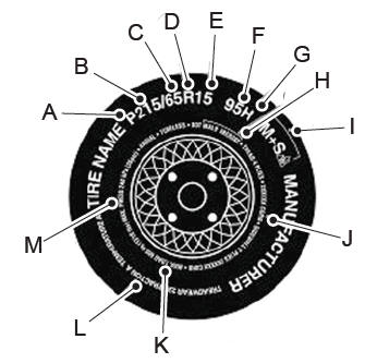
    P215/65R15 95H is an example of a tire size, load index and speed rating. The definitions of these items are listed below. (Note that the tire size, load index and speed rating for your vehicle may be different from this example.)

    P: Indicates a tire, designated by the Tire and Rim Association, that may be used for service on cars, sport utility vehicles, minivans and light trucks. Note: If your tire size does not begin with a letter this may mean it is designated by either the European Tire and Rim Technical Organization or the Japan Tire Manufacturing Association. 215: Indicates the nominal width of the tire in millimeters from sidewall edge to sidewall edge. In general, the larger the number, the wider the tire. 65: Indicates the aspect ratio which gives the tire's ratio of height to width. R: Indicates a radial type tire. 15: Indicates the wheel or rim diameter in inches. If you change your wheel size, you will have to purchase new tires to match the new wheel diameter. 95: Indicates the tire's load index. It is an index that relates to how much weight a tire can carry. You may find this information in your owner’s manual. If not, contact a local tire dealer.

    read more

    Copyright © 2024 www.licorsair.com