Lincoln Corsair: Automatic Transmission - 8-Speed Automatic Transmission – 8F35/8F40 / Overhaul - Transmission
Special Tool(s) / General Equipment
 |
100-002
(TOOL-4201-C)
Holding Fixture with Dial Indicator Gauge |
 |
205-153
(T80T-4000-W)
Handle |
 |
205-199
(T83T-3132-A1)
Installer, Spindle/Axle Shaft T83-4000-A TKIT-1983-F TKIT-1983-FLM TKIT-1983-FX |
 |
307-003
(T57L-500-B)
Holding Fixture, Transmission |
 |
307-091 Handle, Torque Converter TKIT-2009TC-F |
 |
307-300 Gauge Bar, Shim Selection TKIT-1994-LMH/MH2 TKIT-1994-F TKIT-1994-FLM/FM |
 |
307-300-01 Adapter for 307-300 TKIT-1994-LMH/MH2 TKIT-1994-F TKIT-1994-FLM/FM |
 |
307-566 Retainer, Torque Converter TKIT-2006C-FFMFLM TKIT-2006C-LM TKIT-2006C-ROW |
 |
307-574 Forward Clutch Spring Compressor TKIT-2006UF-FLM TKIT-2006UF-ROW |
 |
307-578 Input Shaft Support Seal Installer (Back Plate, Multiple rings) TKIT-2006UF-FLM TKIT-2006UF-ROW |
 |
307-581 Manual lever seal installer TKIT-2006UF-FLM TKIT-2006UF-ROW |
 |
307-584 2-6 Spring Compressor TKIT-2006UF-FLM TKIT-2006UF-ROW |
 |
307-589 Overdrive clutch and balance piston service set TKIT-2006UF-FLM TKIT-2006UF-ROW |
 |
307-691 Tester, Torque Convertor Leak |
 |
307-732 Tool Kit, Torque Converter Flusher |
 |
307-758 Installer, Axle Seal -FWD |
 |
307-760 Installer, Converter Seal |
 |
307-761 Installer,Turbine Seal |
 |
307-762 Staking Tool, Turbine Seal |
 |
307-763 Tool, Turbine Seal Deburring |
 |
307-764 Installer/Sizer, Stator Teflon Seal |
 |
307-765 Protector, Turbine Seal |
 |
307-766 Installer, Input Shaft Snap Ring |
 |
307-767 Compressor, 3-8 Spring |
 |
307-769 Fixture, Bench Mount |
 |
307-770 Compressor,1-5_2-8 Piston Spring |
 |
307-771 Accumulator Release Pin |
| Flat Headed Screw Driver | |
| Dial Indicator | |
| Slide Hammer | |
| Hydraulic Press | |
| Punch | |
| Locking Pliers | |
Materials
| Name | Specification |
|---|---|
| Motorcraft® MERCON® ULV Automatic Transmission Fluid XT-12-QULV |
WSS-M2C949-A, MERCON® ULV |
| Motorcraft® Ultra Silicone Sealant TA-29 |
WSS-M4G323-A8 |
| Petroleum Jelly | - |
All vehicles
-
For information on component views and base part numbers.
Refer to: Transmission Description (307-01A Automatic Transmission - 8-Speed Automatic Transmission – 8F35/8F40, Description and Operation).
-
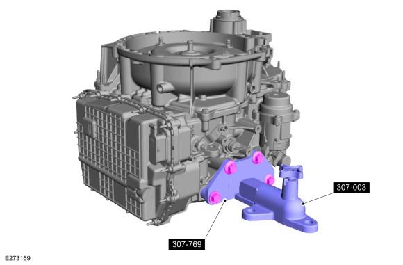
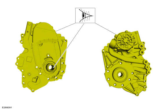
Using the special tool, secure the transmission to the bench mounted fixture.
Use Special Service Tool: 307-769 Fixture, Bench Mount. , 307-003 (T57L-500-B) Holding Fixture, Transmission.
 |
-
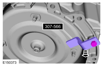
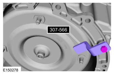
Remove the special tool.
Use Special Service Tool: 307-566 Retainer, Torque Converter.
 |
-
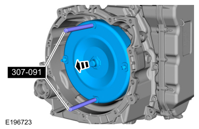
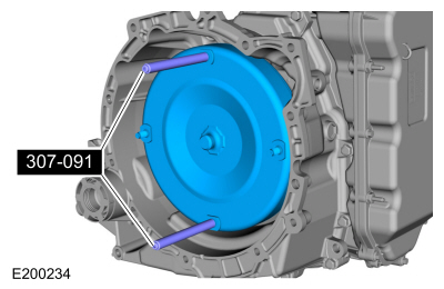
NOTICE: The torque converter is heavy. Be careful not to drop it or damage will result.
Using the special tools, remove the torque converter.
Use Special Service Tool: 307-091 Handle, Torque Converter.
 |
-
A new or remanufactured torque converter must be installed if one or more of the following statements are true:
-
The sealing surface has a groove worn from the seal.
-
A torque converter malfunction has been determined based on complete diagnostic procedures.
-
The torque converter stud or studs, threaded pads, impeller hub or bushing are damaged.
-
The torque converter exhibits external discoloration (due to overheating).
-
There is evidence of water or antifreeze contamination.
-
The sealing surface has a groove worn from the seal.
 |
Flush The Torque Converter With The Transmission Cooling System Heated Flusher
-
NOTE: Use transmission fluid specified for this transmission. Do not use any supplemental transmission fluid additives or cleaning agents. The use of these products could cause internal transmission components to fail, which will affect the operation of the transmission.
The torque converter must be flushed every time the transmission is overhauled. It is mandatory that proper equipment and procedures be followed when flushing the torque converter. The flushing equipment used MUST:
-
Maintain the transmission fluid at 140°F or above
-
Pulsate the transmission fluid during cleaning
-
Have a GPM flow meter
-
Have a filter with a rating of 100 micron or less
-
Have air purge capability before and after flushing
-
Maintain the transmission fluid at 140°F or above
-
Check and top off the transmission fluid level of the
transmission cooling system heated flusher with transmission fluid.
-
Turn on the heater and allow the transmission fluid in
the transmission cooling system heated flusher 15-30 minutes to heat up
to 60°C (140°F) before using.
-
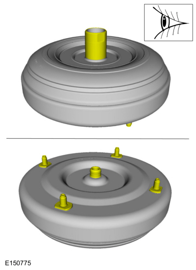
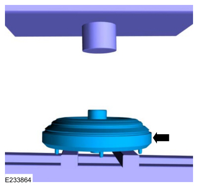
Place the torque converter in an arbor press. Support the torque converter on the mounting pads.
 |
-
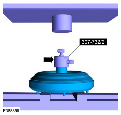
Using the special tools, assemble the correct turbine
shaft simulator to the torque converter flush main hub and place it on
the torque converter hub.
Use Special Service Tool: 307-732 Tool Kit, Torque Converter Flusher.
 |
-
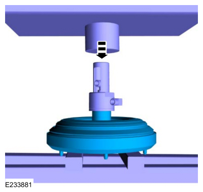
Using the special tool, install the slotted cap.
Use Special Service Tool: 307-691 Tester, Torque Convertor Leak.
 |
-
Apply enough force from the press to seal the torque converter flush main hub to the torque converter hub.
 |
-
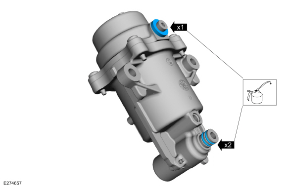
Connect the flush machine to the main hub.
-
Red hose on top.
-
Blue hose on bottom.
-
Red hose on top.
 |
-
Follow the equipment instructions to purge transmission
fluid from the torque converter prior to starting the flushing
procedure.
-
 WARNING:
The torque converter, adaptor 307-732, and the hoses will be hot.
WARNING:
The torque converter, adaptor 307-732, and the hoses will be hot.
NOTE: Maintain visual contact with torque converter during the entire flush procedure. Immediately stop the flush machine if a leak develops. Repeat set up steps to reseal the tool to the converter hub and continue flushing.
Forward flush the converter for 15 minutes.
-
Monitor GPM flow meter periodically during the flush
procedure. Flow rate above 2.0 gallons per minute is required to break
up and dislodge any contamination trapped behind the TCC plate. Service flush machine filter(s) if flow rate drops below 2 GPM.
-
Follow the equipment instructions to purge the torque converter.
-
Allow torque converter and equipment to cool for 30 minutes before handling.
WARNING:
The torque converter, adaptor 307-732, and the hoses will be hot.
-
Disconnect the hoses and remove the special tools.
All vehicles
-
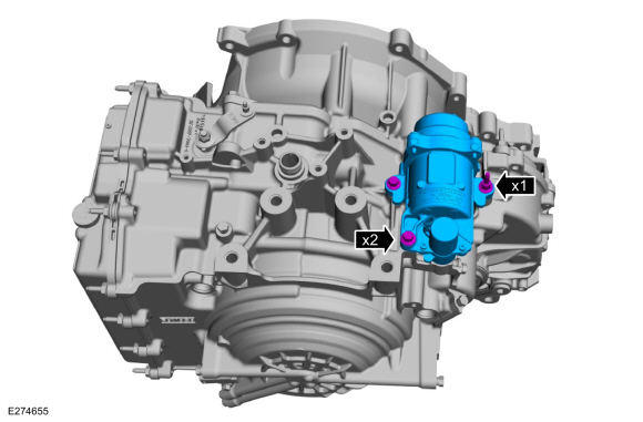
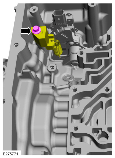
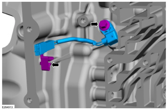
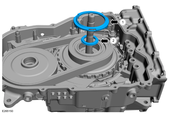
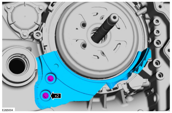
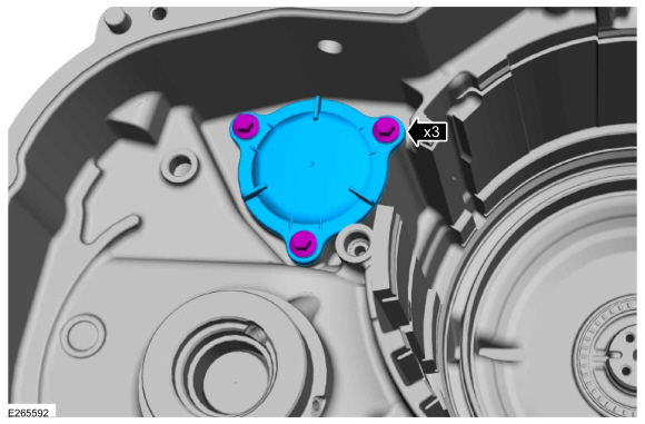
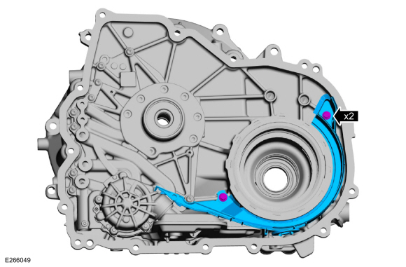
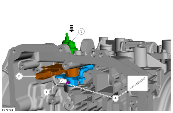
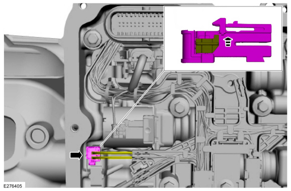
Remove the bolts, studbolt and the start/stop accumulator.
 |
-
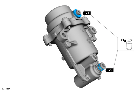
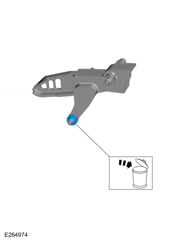
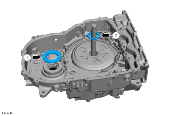
Remove and discard the start/stop accumulator O-rings.
 |
-
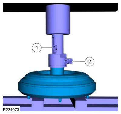
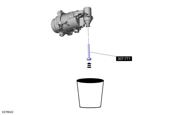
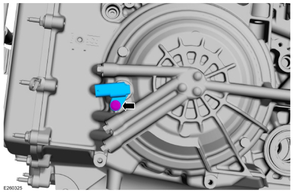
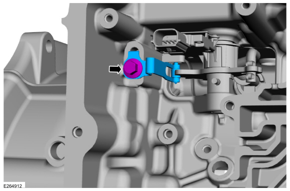
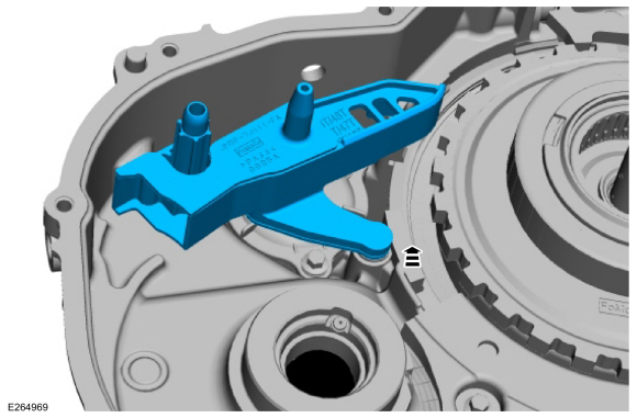
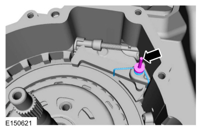
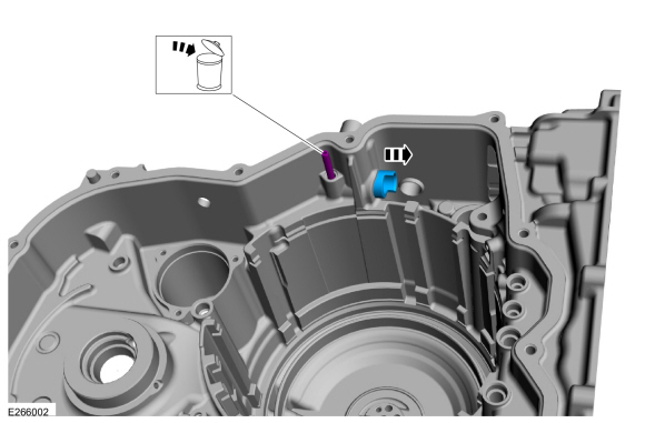
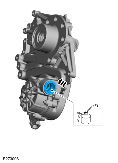
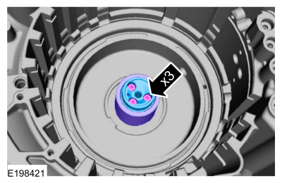
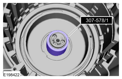
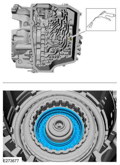
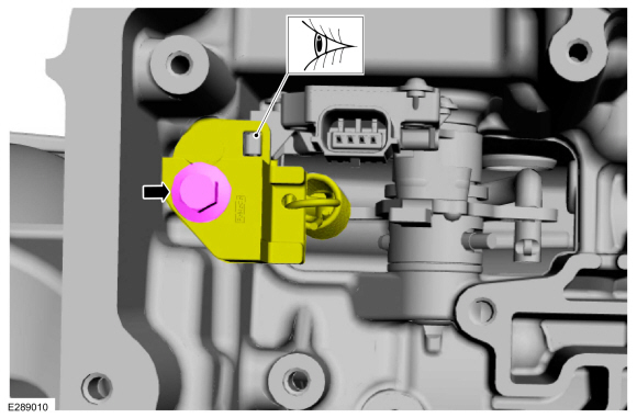
NOTICE: Do not disassemble, the start/stop accumulator is under pressure.
Using the special tool, discharge the start/stop accumulator into a suitable container.
Use Special Service Tool: 307-771 Accumulator Release Pin.
 |
-
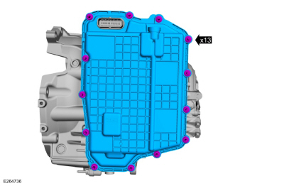
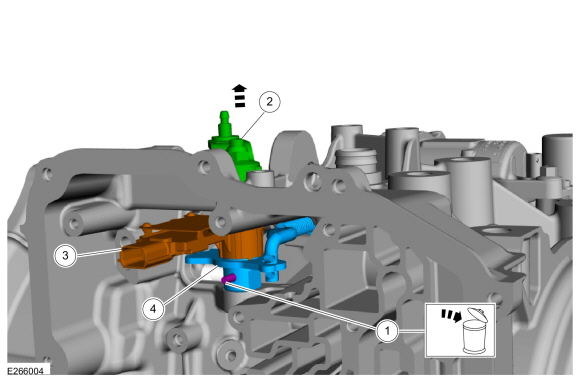
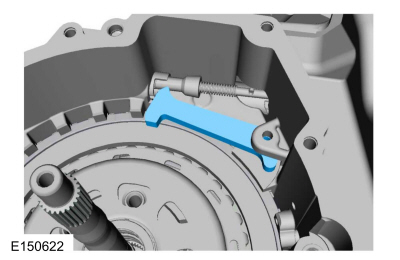
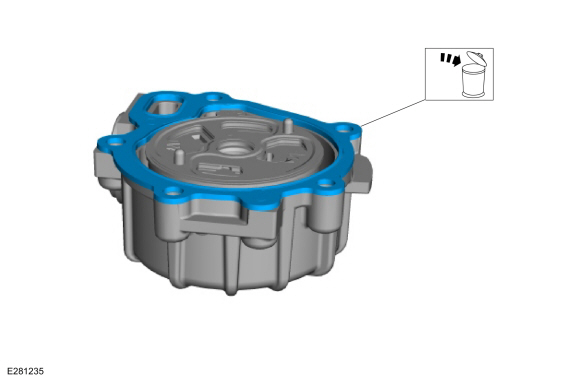
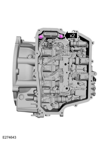
Remove the stud bolts and the main control cover.
 |
-
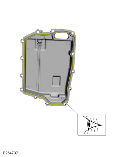
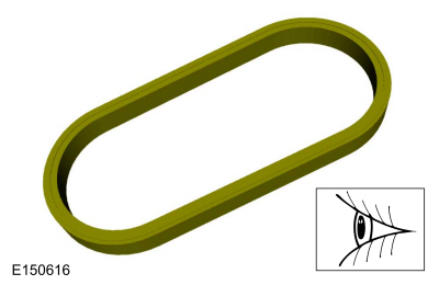
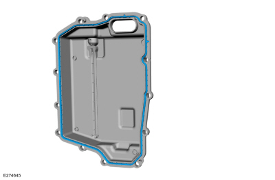
Inspect the main control cover seal for damage and install new if necessary.
 |
-
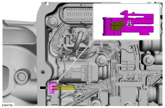
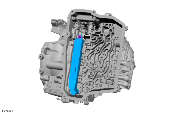
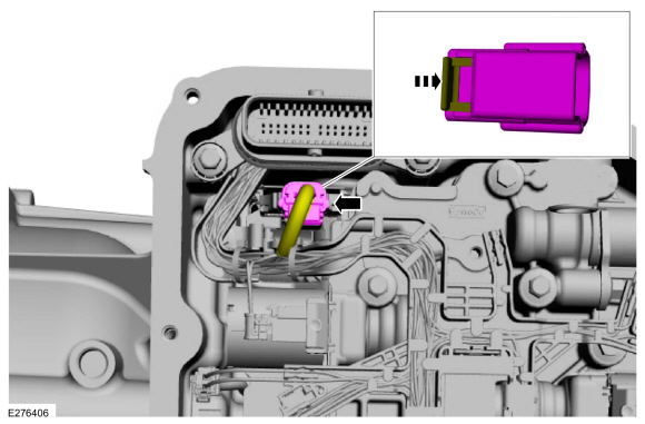
Unlock and disconnect the OSS sensor electrical connector.
 |
-
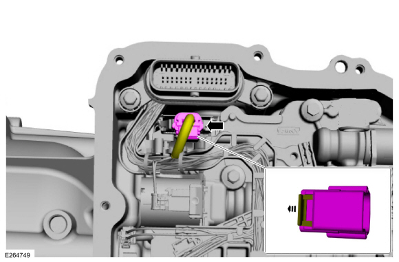
Unlock and disconnect the TR sensor electrical connector.
 |
-
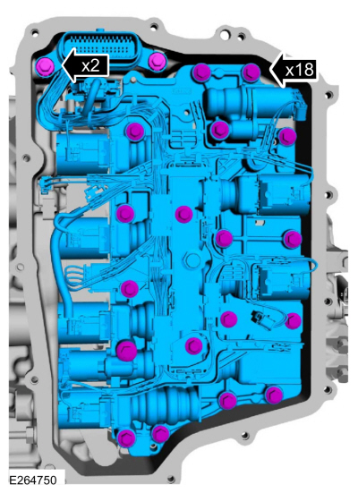
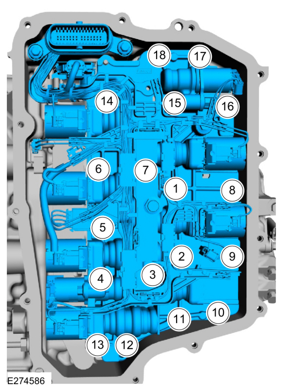
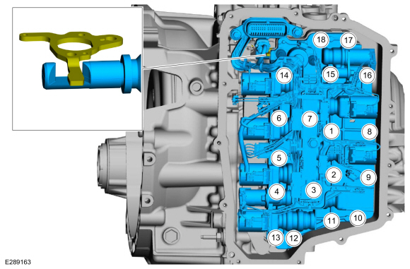
NOTE: Note the location of the short and long main control valve body bolts for assembly.
Remove the bolts, main control valve body and transmission wiring harness assembly.
 |
-
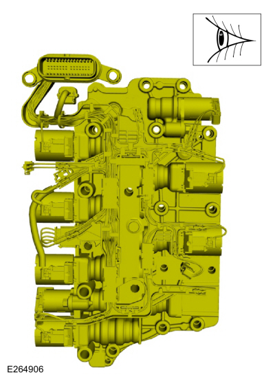
Inspect the main control assembly for damage. If damage
is found install a new main control assembly. If the main control
assembly is not damaged, disassemble and clean it.
Refer to: Main Control Valve Body (307-01A Automatic Transmission - 8-Speed Automatic Transmission – 8F35/8F40, Overhaul).
 |
-
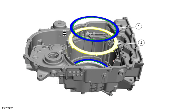
Remove and discard the A (1, 2, 3, 4, 5), C (3, 7), F
(2, 8), and the D (SOWC) clutch main control valve body case seals.
 |
-
Remove the bolt and the TSS/ISSA (Turbine Shaft Speed/Intermediate Shaft Speed) sensor assembly.
 |
Vehicles with Park-By-Wire
-
Remove the bolt and position aside the park-by-wire support bracket and spring.
 |
-
Using locking pliers and slide hammer, remove and discard the roll pin. Remove the following items.
-
Roll pin
-
Manual control shaft and lever
-
TR sensor and park pawl actuator rod as an assembly
-
Roll pin
 |
Vehicles with Cable Shift
-
Remove the bolt and the TR sensor detent spring.
 |
-
Using locking pliers and slide hammer, remove and discard the roll pin.
-
Roll pin
-
Manual control shaft and lever
-
TR sensor
-
Manual valve detent lever and park pawl actuator rod as an assembly
Use the General Equipment: Slide Hammer
Use the General Equipment: Locking Pliers
-
Roll pin
 |
All vehicles
-
Remove the bolt and the transmission fluid transfer pipe.
 |
-
Remove the bolt, the wire harness clip and the OSS sensor.
 |
-
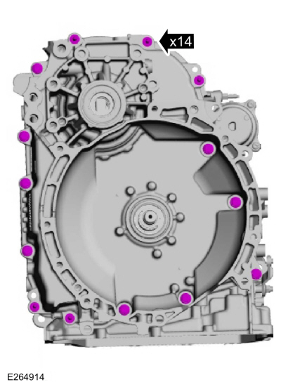
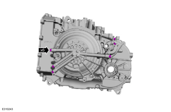
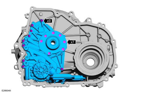
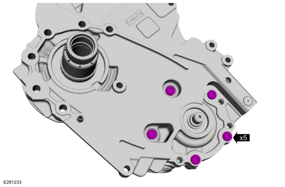
NOTE: Note the location of the stud bolts for assembly.
Remove the torque converter housing bolts and stud bolts.
 |
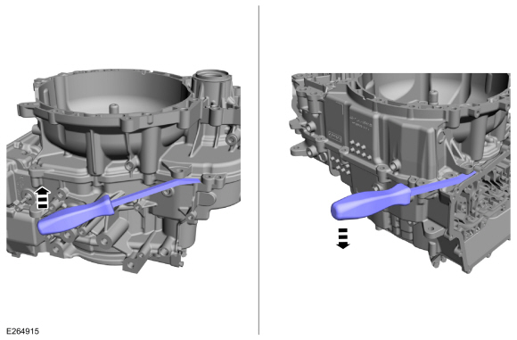
-
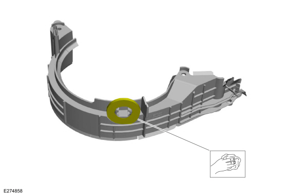
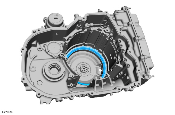
Pry the torque converter housing loose from the transmission case.
Use the General Equipment: Flat Headed Screw Driver
 |
-
Remove the torque converter housing from the transmission case.
 |
-
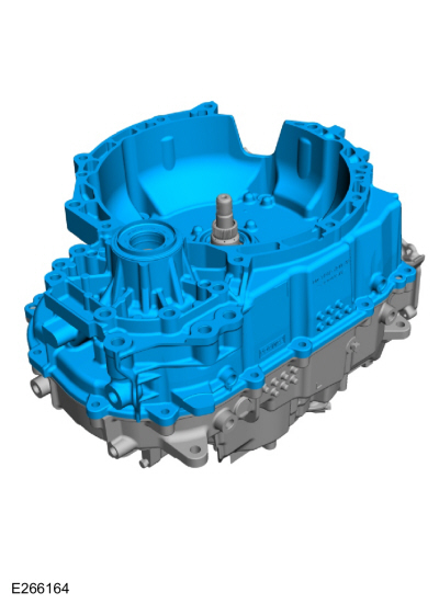
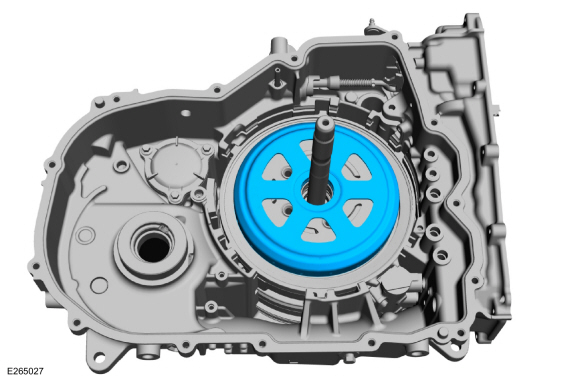
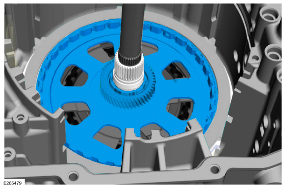
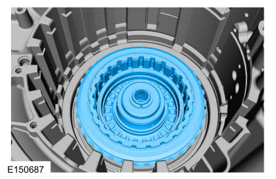
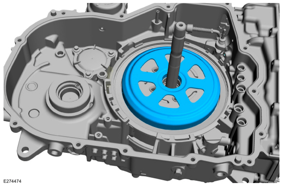
Remove the differential assembly.
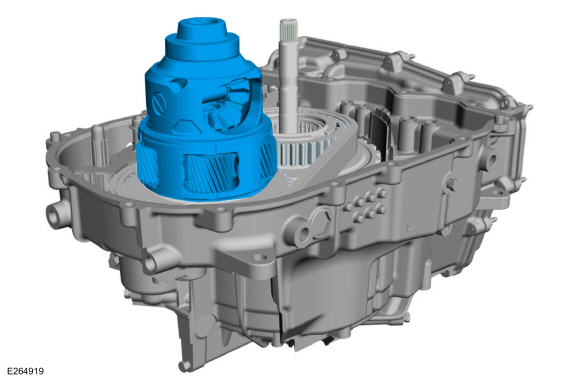 |
-
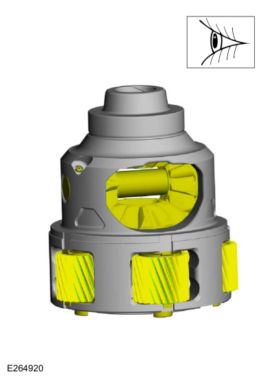
Check that the bearings spin freely, do not move back
and forth or move side to side excessively. Check for damage or
excessive wear. Install a new differential, if necessary.
 |
-
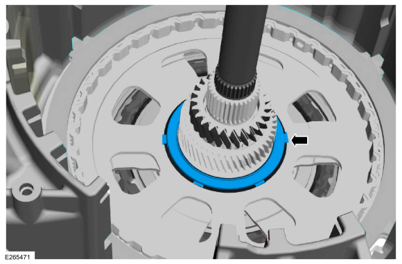
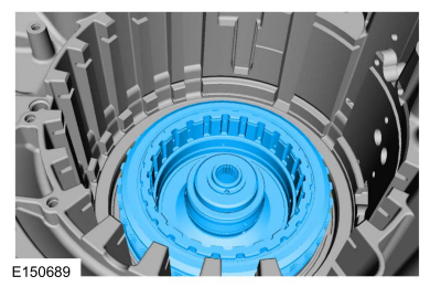
Remove the No. 16 thrust bearing.
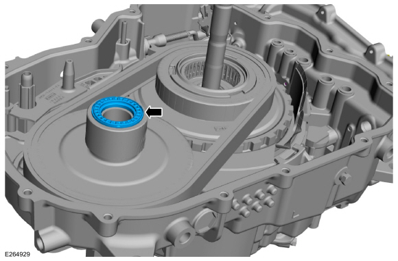 |
-
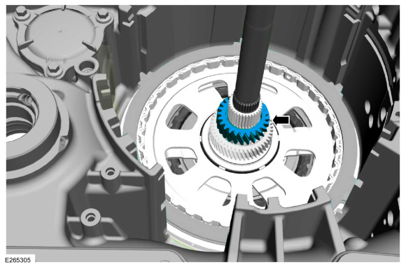
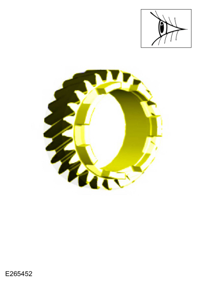
Remove the differential sun gear.
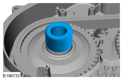 |
-
Inspect the differential sun gear for damage or wear, install new as necessary.
 |
-
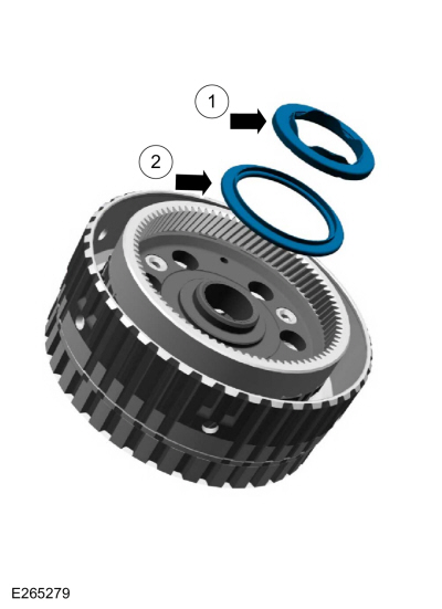
Remove the following items.
-
Plastic thrust bearing
-
No. 13 thrust bearing
-
Plastic thrust bearing
 |
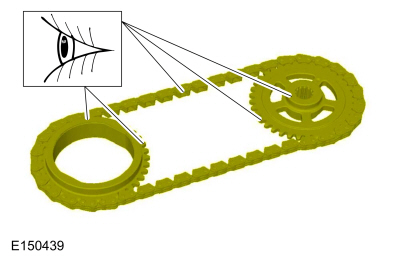
-
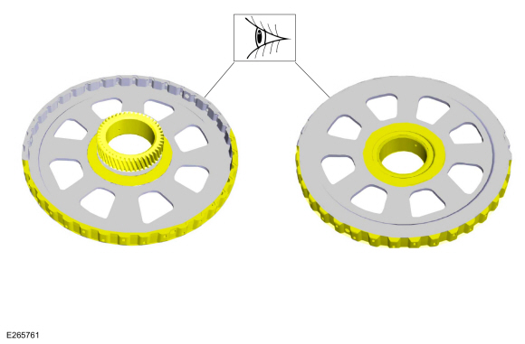
Simultaneously remove the driven sprocket and the chain.
 |
-
Remove and discard the clutch feed seals.
 |
-
Remove the chain snubber.
 |
-
Remove and discard the chain snubber seal.
 |
-
Remove the output drive hub assembly.
 |
-
Remove the drive chain from the driven sprocket.
 |
-
Clean and inspect the drive chain for damage or excessive wear, install new if necessary.
-
Check for stretching or tightness of the chain links.
-
Check that the chain moves freely.
-
Check for stretching or tightness of the chain links.
 |
-
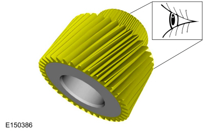
Inspect the driven sprocket for damage or excessive wear, install new if necessary.
-
Chain teeth
-
Spline teeth
-
Thrust bearing surfaces
-
Bearing
-
Chain teeth
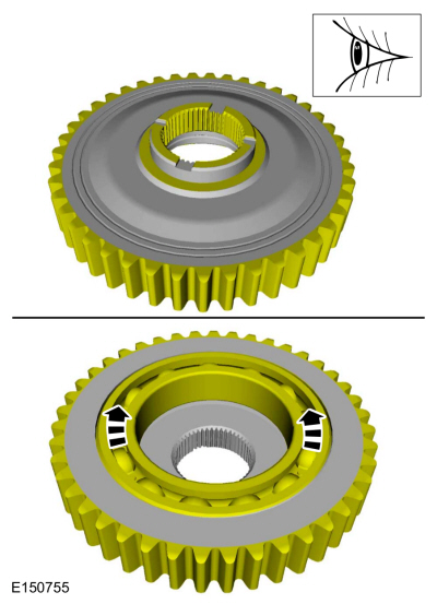 |
-
Remove the snap ring and remove the drive sprocket from the output planetary hub/park gear assembly.
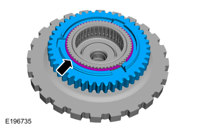 |
-
Inspect the drive sprocket for damage or excessive wear, install new if necessary.
-
Chain teeth
-
Spline teeth
-
Thrust washer surface
-
Chain teeth
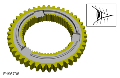 |
-
Inspect the output planetary hub/park gear assembly for damage or excessive wear, install new if necessary.
-
Park gear teeth
-
Spline teeth
-
Thrust washer surface
-
Thrust bearing surface
-
Bearing surfaces
-
Needle bearing
-
Park gear teeth
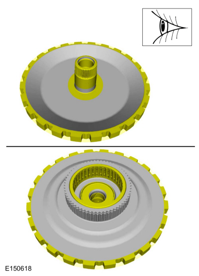 |
-
Install the drive sprocket on the output planetary hub/park gear assembly and install the snap ring.
|
-
Install the drive chain onto the driven sprocket.
|
-
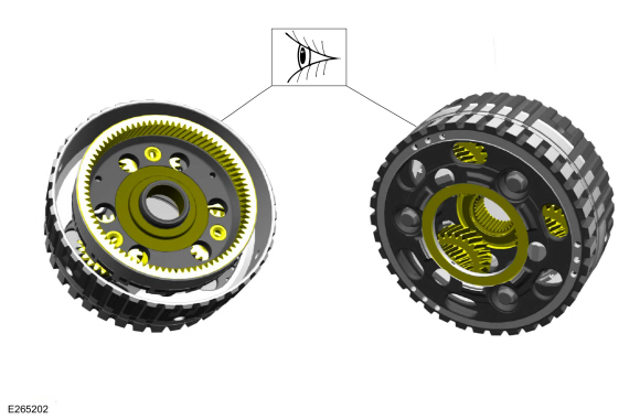
Remove the following items.
-
No. 15 thrust bearing
-
No. 12 thrust bearing
-
No. 15 thrust bearing
 |
-
Remove the bolts and the transmission fluid baffle.
 |
-
Remove the park pawl pin and spring.
 |
-
Remove the park pawl.
 |
-
Remove the output planetary sun gear and shell assembly.
 |
-
Clean and inspect the output planetary sun gear and shell assembly for damage or wear, install new as necessary.
 |
-
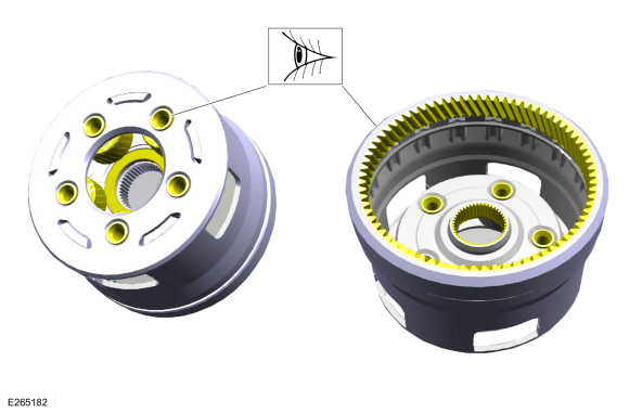
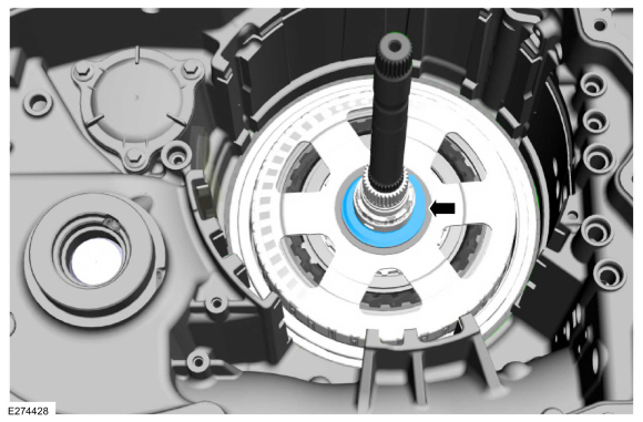
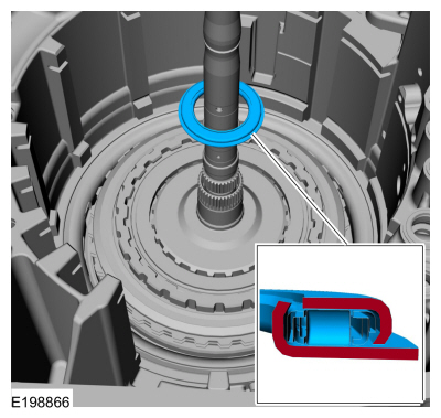
NOTE: The Hydraulic Selectable One-Way Clutch (SOWC) snap ring is beveled. The beveled side of the snap ring goes up (flat side down).
NOTE: The Hydraulic Selectable One-Way Clutch (SOWC) snap ring gap faces the front of the transmission.
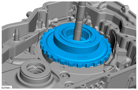
Remove the hydraulic selectable one-way clutch (SOWC) snap ring.
 |
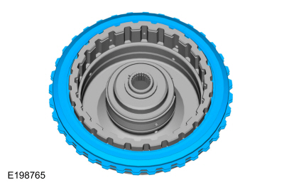
-
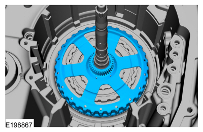
Remove the hydraulic selectable one-way clutch (SOWC).
 |
-
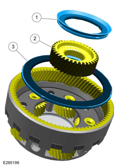
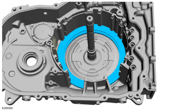
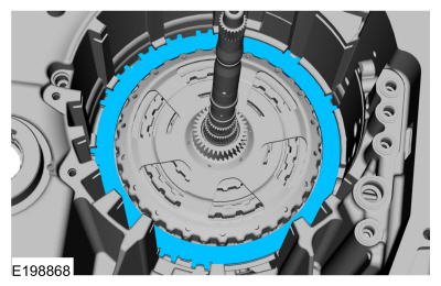
Remove the output, input and reaction/overdrive planetary carrier/ring gear assembly.
 |
-
Seperate the output carrier assembly from the input
carrier assembly. Clean and inspect the output carrier/ring gear
assembly for damage or excessive wear, install new as necessary.
 |
-
Seperate the input carrier assembly from the reaction/overdrive carrier assembly. Remove the No. 9 and the No. 10 thrust bearings. Remove the input carrier sun gear. Clean and inspect the input carrier/ring gear assembly and sun gear for damage or excessive wear, install new as necessary.
-
No. 10 thrust bearing
-
Input sun gear
-
No. 9 thrust bearing
-
No. 10 thrust bearing
 |
-
Remove the following items.
-
No. 7 thrust bearing
-
No. 8 thrust bearing
-
No. 7 thrust bearing
 |
-
Clean and inspect the reaction/overdrive carrier/ring
gear assembly for damage or excessive wear, install new as necessary.
 |
-
Remove the S-3 sun gear.
 |
-
Clean and inspect the S-3 planetary sun gear for damage or excessive wear, install new as necessary.
 |
-
Remove the F (2, 8) clutch piston assembly.
 |
-
Remove the No. 5 thrust bearing.
 |
-
Remove the F (2, 8) clutch sun gear and shell assembly.
 |
-
Clean and inspect the F (2, 8) clutch sun gear and shell
assembly for damage or excessive wear, replace as necessary.
 |
-
Remove the No. 4 thrust bearing.
 |
-
Remove the F (2, 8) clutches and pressure plate.
 |
-
Inspect the F (2, 8) clutches and plates for damage or excessive wear, install new if necessary.
-
F (2, 8) clutch Steel plate
-
F (2, 8) clutch friction plate
-
F (2, 8) clutch Steel plate
 |
-
Inspect the C (3, 7)/F (2, 8) clutch pressure plate for damage or excessive wear, install new if necessary.
 |
-
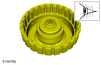
Remove the B (4, 6, R) clutch shell and C (3, 7) clutches as an assembly.
 |
-
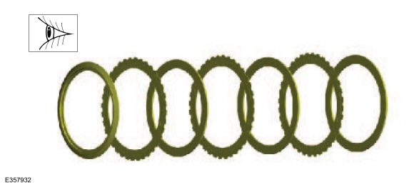
Inspect the C (3, 7) clutch plates for damage or excessive wear, install new if necessary.
-
C (3, 7) clutch friction plate
-
C (3, 7) clutch steel plate
-
Wave plate
-
C (3, 7) clutch friction plate
 |
-
Clean and inspect the B (4, 6, R) and C (3, 7) clutch
shell assembly for damage or excessive wear, install new as necessary.
 |
-
Remove the No. 3 thrust bearing.
 |
-
Remove the B (4, 6, R)/E (5, 6, 7, 8) clutch assembly.
 |
-
Remove the No. 1 thrust bearing.
 |
-
Remove the bolts and the clutch support tower.
 |
-
Remove the C (3, 7) clutch piston apply ring.
 |
-
NOTE: Note the location of the snap ring gap for assembly.
Release the C (3, 7) clutch return spring snap ring.
 |
-
NOTE: Note the location of the C (3, 7) clutch piston snap ring gap, the piston return spring tab and the piston bleed hole for assembly.
Remove the following items.
-
C (3, 7) clutch piston snap ring
-
C (3, 7) clutch piston return spring
-
C (3, 7) clutch piston
-
C (3, 7) clutch piston snap ring
 |
-
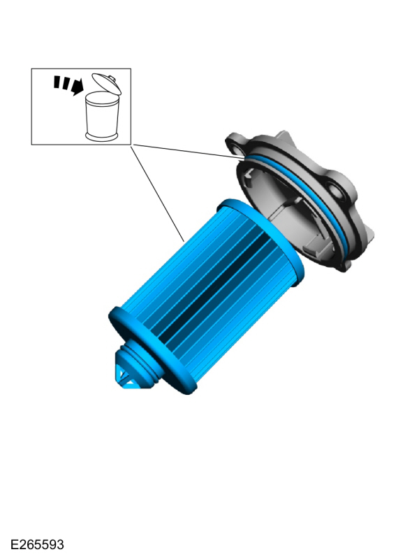
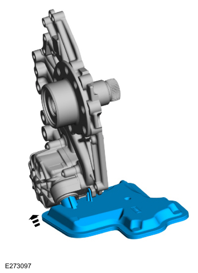
Remove the bolts and the transmission fluid filter cover and transmission fluid filter.
 |
-
Remove and discard the transmission filter and O-ring seal.
 |
-
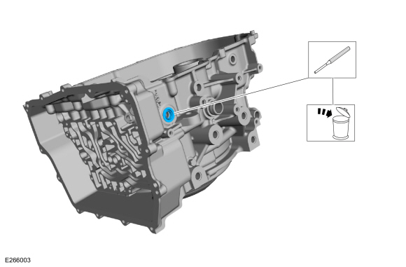
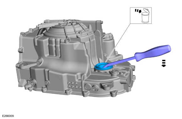
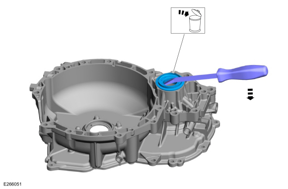
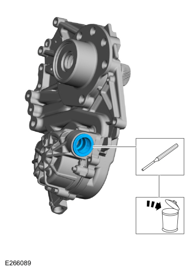
Remove and discard the manual control shaft seal.
Use the General Equipment: Flat Headed Screw Driver
 |
-
NOTE: This step is not required unless replacing the transmission case assembly.
Using locking pliers and a slide hammer, remove and discard the roll pin. Remove the park pawl rod guide.
Use the General Equipment: Locking Pliers
Use the General Equipment: Slide Hammer
 |
-
Remove and discard the LH halfshaft seal.
Use the General Equipment: Flat Headed Screw Driver
 |
-
-
NOTICE: If the LH transmission case bushing or the LH halfshaft bushing surface shows signs of excessive wear or damage, a new transmission case and a new LH halfshaft must be installed, or transmission failure can occur.
Clean and inspect the LH transmission case bushing and the bushing surface on the LH halfshaft for damage or excessive wear. If the LH transmission case bushing or the LH halfshaft shows signs of excessive wear or damage, install new components.
-
NOTICE: Do not use metal scrapers, wire brushes, power abrasive discs, or other abrasive means to clean sealing surfaces. These tools cause scratches and gouges which make leak paths.
Make sure that the case half sealing surface is clean and free of foreign material.
Refer to: RTV Sealing Surface Cleaning and Preparation (303-00 Engine System - General Information, General Procedures).
-
NOTICE: Do not use metal scrapers, wire brushes, power abrasive discs, or other abrasive means to clean sealing surfaces. These tools cause scratches and gouges which make leak paths.
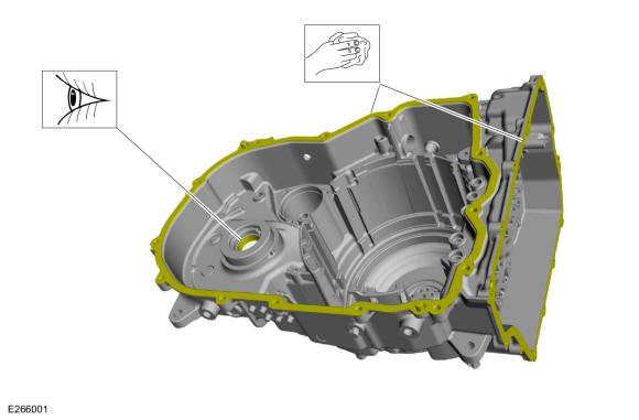
Clean and inspect the main control cover gasket sealing surface.
-
 |
-
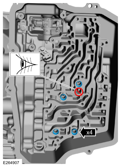
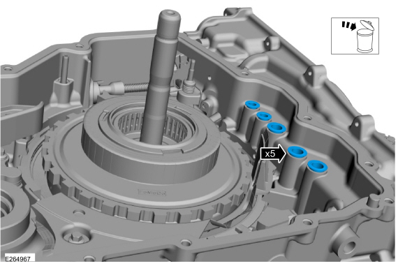
Verify torque for all pressure test port plugs.
Torque: 106 lb.in (12 Nm)
 |
-
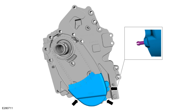
Remove the bolts and the transmission fluid baffle.
 |
-
Clean the magnet on the bottom of the transmission fluid baffle.
 |
-
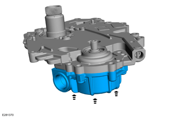
Remove the bolts and the transmission fluid pump assembly.
 |
-
Remove, clean and inspect the following items for the torque converter housing.
-
Plastic thrust washer
-
Chain snubber assembly lubrication seal
-
No. 17 thrust bearing
-
Plastic thrust washer
 |
-
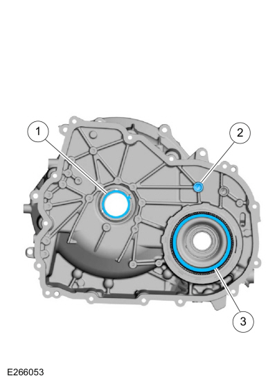
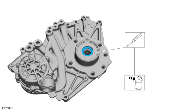
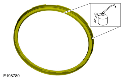
Remove and discard the torque converter hub seal.
Use the General Equipment: Flat Headed Screw Driver
 |
-
Remove and discard the RH halfshaft seal.
Use the General Equipment: Flat Headed Screw Driver
 |
-
-
Inspect the torque converter housing for damage or excessive wear, install new as necessary.
-
NOTICE: Do not use metal scrapers, wire brushes, power abrasive discs, or other abrasive means to clean sealing surfaces. These tools cause scratches and gouges which make leak paths.
Make sure that the mating faces are clean and free of foreign material.
Refer to: RTV Sealing Surface Cleaning and Preparation (303-00 Engine System - General Information, General Procedures).
-
Inspect the torque converter housing for damage or excessive wear, install new as necessary.
 |
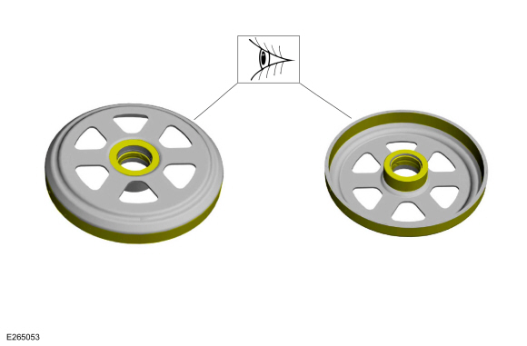
-
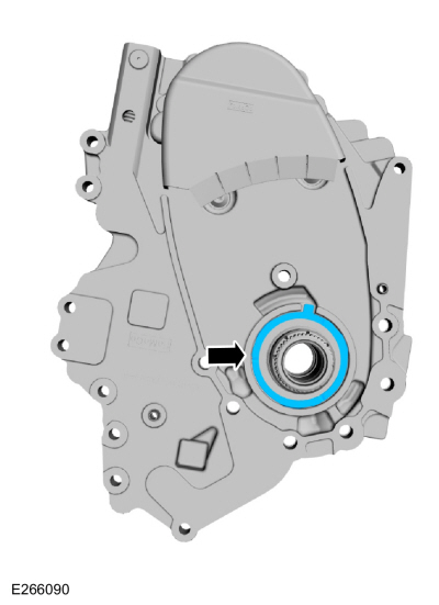
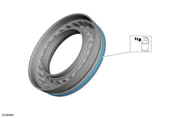
Remove the snap ring and the differential ring gear.
 |
-
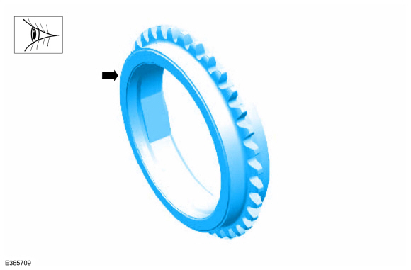
Inspect the differential ring gear for damage or excessive wear, install new as necessary.
 |
-
NOTE: Note the orientation of the transmission fluid filter to the transmission fluid pump assembly.
Remove and discard the transmission fluid filter.
 |
-
Inspect the transmission fluid pump assembly and the
input shaft bushing for damage or excessive wear, install new if
necessary.
 |
-
Remove and discard the transmission fluid filter seal.
Use the General Equipment: Punch
 |
-
Remove the transmission fluid pump chain cover.
 |
-
Remove the transmission fluid pump driven sprocket snap ring and the chain and sprockets.
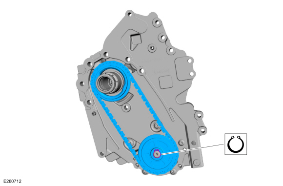 |
-
Inspect the transmission fluid pump chain and sprocket assembly for damage or wear, install new if necessary.
 |
-
NOTE: Note position of locating tab on thrust washer.
Remove the transmission fluid pump drive sprocket thrust washer.
 |
-
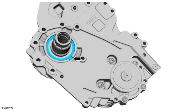
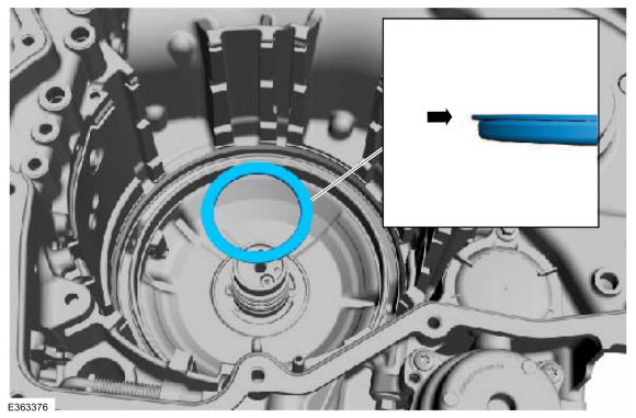
Remove and discard the stator seal.
 |
-
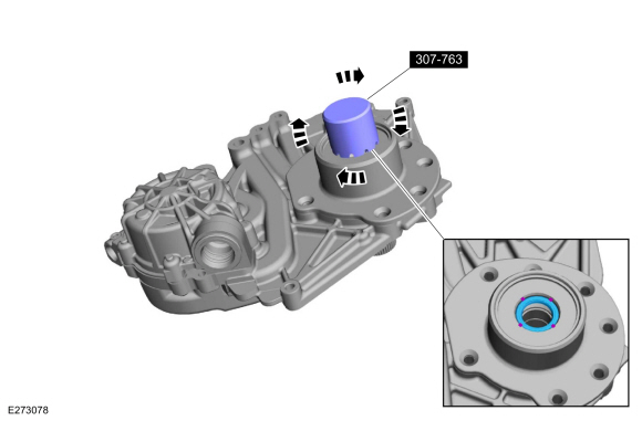
Using the special tool, debur the turbine shaft seal bore opening.
Use Special Service Tool: 307-763 Tool, Turbine Seal Deburring.
 |
-
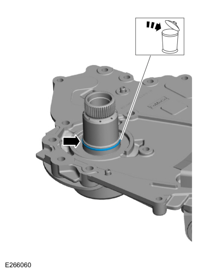
Remove and discard the turbine shaft seal.
Use the General Equipment: Punch
 |
-
Clean the turbine shaft seal bore.
 |
-
Remove the transmission fluid pump bolts.
 |
-
Remove the transmission fluid pump.
 |
-
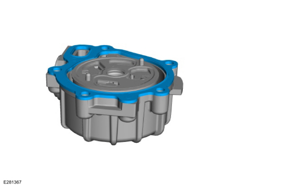
Remove and discard the transmission fluid pump housing gasket.
 |
-
Remove and discard the transmission fluid pump gasket.
 |
-
Remove the transmission fluid pump plate.
 |
-
Remove the transmission fluid pump rotor and vanes.
 |
-
Remove the transmission fluid pump bore ring.
 |
-
Inspect the transmission fluid pump bore ring for damage
or wear, install a new transmission fluid pump assembly if necessary.
 |
-
Clean and inspect the transmission fluid pump components
for damage or excessive wear, install a new transmission fluid pump
assembly if necessary.
 |
-
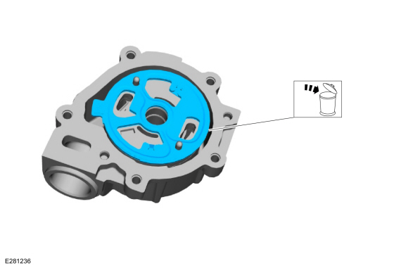
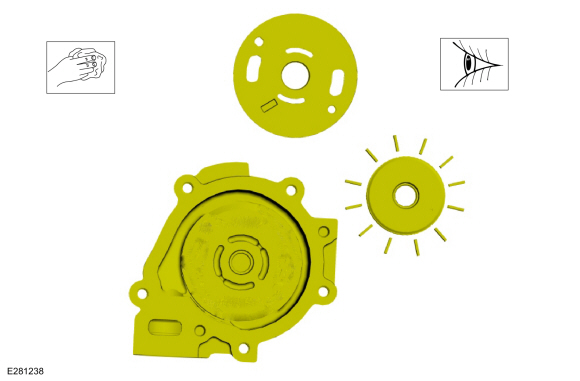
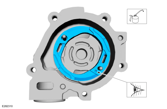
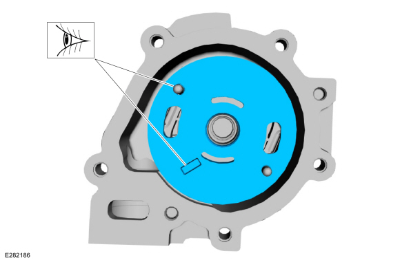
Lubricate and install the bore ring into the
transmission fluid pump housing with the dot facing up at approximately
the 4 o'clock position.
Material: Motorcraft® MERCON® ULV Automatic Transmission Fluid / XT-12-QULV (WSS-M2C949-A, ) (MERCON® ULV)
 |
-
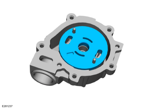
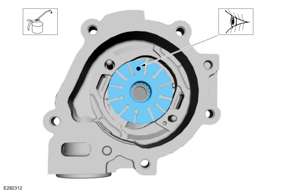
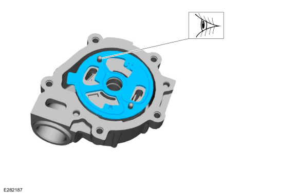
Lubricate and install the transmission fluid pump rotor with the dot at the 12 o'clock position.
Material: Motorcraft® MERCON® ULV Automatic Transmission Fluid / XT-12-QULV (WSS-M2C949-A, ) (MERCON® ULV)
 |
-
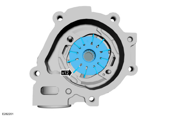
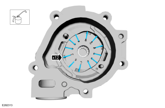
Lubricate and install the transmission fluid pump vanes.
Material: Motorcraft® MERCON® ULV Automatic Transmission Fluid / XT-12-QULV (WSS-M2C949-A, ) (MERCON® ULV)
 |
-
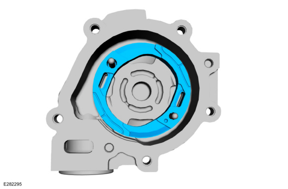
Install the transmission fluid pump bore ring support
with the slotted hole on the upper dowel pin and the rectangular cut-out
facing up.
 |
-
Install a new transmission fluid pump bore ring gasket with the slotted hole on the upper dowel pin.
 |
-
Install a new transmission fluid pump housing gasket.
 |
-
Install the transmission fluid pump.
 |
-
Install the transmission fluid pump bolts.
Torque: 89 lb.in (10 Nm)
|
-
Verify that the transmission fluid pump spins freely.
 |
-
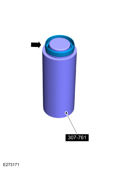
Place the turbine shaft seal on the special tool.
Use Special Service Tool: 307-761 Installer,Turbine Seal.
 |
-
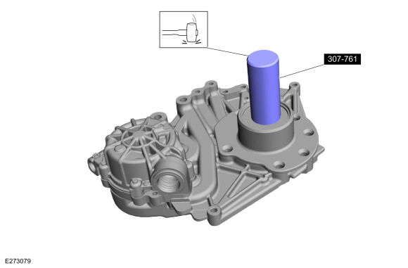
Using the special tool, install the turbine shaft seal.
Use Special Service Tool: 307-761 Installer,Turbine Seal.
 |
-
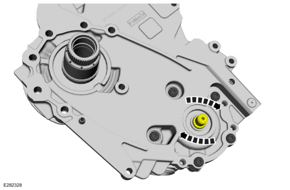
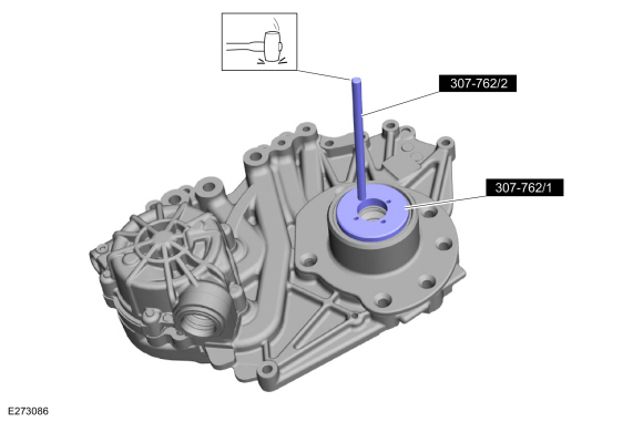
Using the special tool, stake the turbine shaft seal in four locations.
Use Special Service Tool: 307-762 Staking Tool, Turbine Seal.
 |
-
Install a new transmission fluid filter seal. Lubricate
the transmission fluid filter seal with clean transmission fluid.
Material: Motorcraft® MERCON® ULV Automatic Transmission Fluid / XT-12-QULV (WSS-M2C949-A, ) (MERCON® ULV)
 |
-
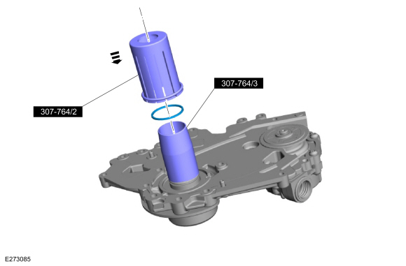
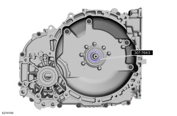
Using the special tools, install the stator seal.
Use Special Service Tool: 307-764 Installer/Sizer, Stator Teflon Seal.
 |
-
NOTE: Note position of locating tab on thrust washer.
Install the transmission fluid pump drive sprocket plastic thrust washer.
 |
-
Make sure the flat side of the sprocket is installed towards the oil pump.
 |
-
Install the transmission fluid pump sprockets, chain and snap ring.
|
-
Install the transmission fluid pump chain cover.
|
-
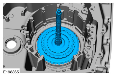
NOTE: The special tool is removed just prior to torque converter installation. It is important to leave the special tool in place until the torque converter is installed, this ensures the correct sizing of the stator seal.
Install the special tool to size the Teflon® seal. Install the O-ring seal around the special tool to hold the transmission fluid pump drive sprocket in place during assembly.
Use Special Service Tool: 307-764 Installer/Sizer, Stator Teflon Seal.
 |
-
Install a new transmission fluid filter.
 |
-
Install differential ring gear and snap ring.
|
-
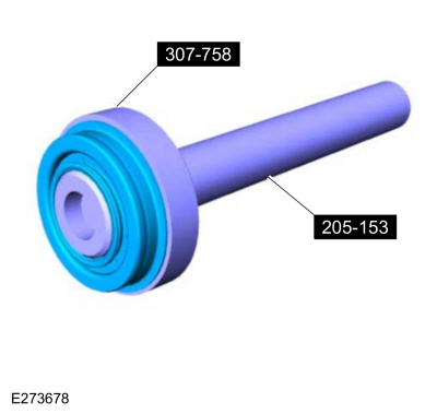
Assemble the special tools and install a new RH halfshaft seal on the special tool.
Use Special Service Tool: 307-758 Installer, Axle Seal -FWD. , 205-153 (T80T-4000-W) Handle.
 |
-
Using the special tools, install the new RH halfshaft seal.
Use Special Service Tool: 205-153 (T80T-4000-W) Handle. , 307-758 Installer, Axle Seal -FWD.
 |
-
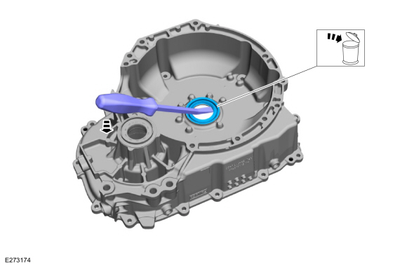
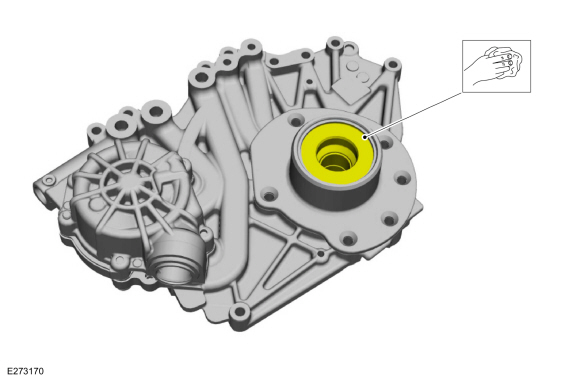
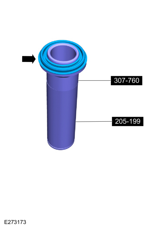
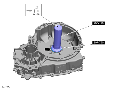
Place a new torque converter hub seal on the special tool.
Use Special Service Tool: 307-760 Installer, Converter Seal. , 205-199 (T83T-3132-A1) Installer, Spindle/Axle Shaft.
 |
-
Using the special tools, install the torque converter hub seal.
Use Special Service Tool: 307-760 Installer, Converter Seal. , 205-199 (T83T-3132-A1) Installer, Spindle/Axle Shaft.
 |
-
Install the following items into the torque converter housing.
-
Plastic thrust washer
-
Chain snubber assembly lubrication seal
-
No. 17 thrust bearing
-
Plastic thrust washer
|
-
Install the transmission fluid pump assembly and the bolts.
Torque: 97 lb.in (11 Nm)
|
-
Install the transmission fluid baffle and the bolts.
Torque: 97 lb.in (11 Nm)
|
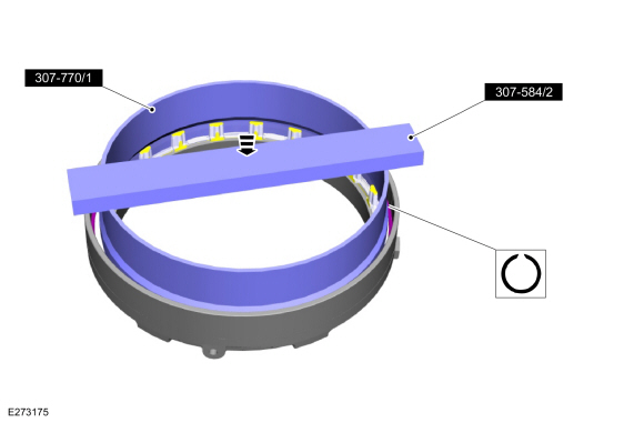
-
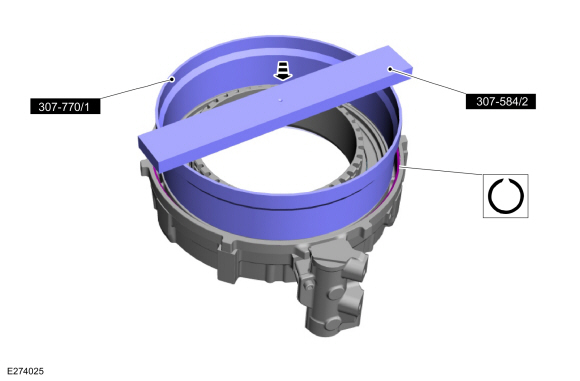
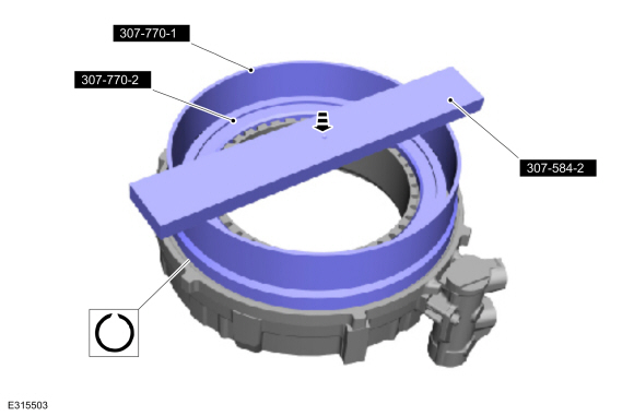
Using the special tool and a press, compress the F (2, 8) clutch return spring and release the snap ring.
Use Special Service Tool: 307-770 Compressor,1-5_2-8 Piston Spring. , 307-584 2-6 Spring Compressor.
Use the General Equipment: Hydraulic Press
 |
-
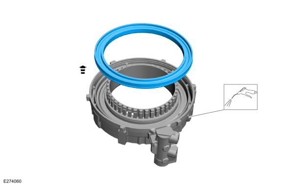
Remove the following items.
-
F (2, 8) clutch piston snap ring
-
F (2, 8) clutch piston return spring
-
F (2, 8) clutch piston
-
F (2, 8) clutch piston snap ring
 |
-
Remove and discard the F (2, 8) clutch piston seal.
 |
-
Inspect the F (2, 8) clutch piston housing for damage or excessive wear, install new if necessary.
 |
-
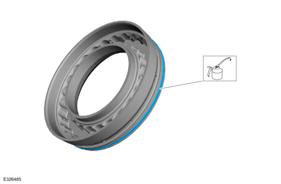
Install a new F (2, 8) clutch piston seal. Lubricate the F (2, 8) clutch piston seal with petroleum jelly.
Material: Petroleum Jelly
 |
-
Position the following items into the F (2, 8) clutch piston housing.
-
F (2, 8) clutch piston snap ring
-
F (2, 8) clutch piston return spring
-
F (2, 8) clutch piston
-
F (2, 8) clutch piston snap ring
|
-
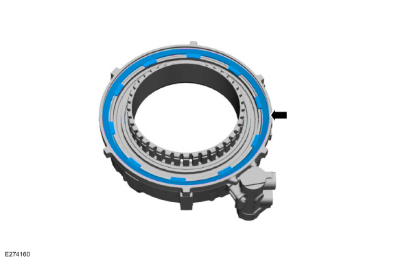
Using the special tool and a press, compress the F (2, 8) clutch return spring and engage the snap ring.
Use Special Service Tool: 307-770 Compressor,1-5_2-8 Piston Spring. , 307-584 2-6 Spring Compressor.
Use the General Equipment: Hydraulic Press
|
-
Remove the A (1, 2, 3, 4, 5) clutch pressure plate snap ring.
 |
-
Remove the A (1, 2, 3, 4, 5) clutch pressure plate.
 |
-
Remove the following items.
-
A (1, 2, 3, 4, 5) clutch friction plate
-
A (1, 2, 3, 4, 5) clutch steel plate
-
A (1, 2, 3, 4, 5) clutch piston return spring
-
A (1, 2, 3, 4, 5) clutch friction plate
 |
-
Inspect the pressure plate and the clutch plate surfaces for damage or excessive wear.
 |
-
Using the special tools and a press, remove the A (1, 2, 3, 4, 5) clutch piston snap ring.
Use Special Service Tool: 307-584 2-6 Spring Compressor. , 307-770 Compressor,1-5_2-8 Piston Spring.
Use the General Equipment: Hydraulic Press
 |
-
Remove the A (1, 2, 3, 4, 5) clutch piston return spring.
 |
-
Using compressed air, remove the A (1, 2, 3, 4, 5) clutch piston.
 |
-
Remove and discard the A (1, 2, 3, 4, 5) clutch piston seals.
 |
-
Inspect the hydraulic selectable one-way clutch (SOWC)
housing for damage or excessive wear, install new if necessary.
 |
-
Material: Petroleum Jelly
Install new A (1, 2, 3, 4, 5) clutch piston seals and lubricate the seals with petroleum jelly.
 |
-
Install the A (1, 2, 3, 4, 5) clutch piston.
 |
-
Install the A (1, 2, 3, 4, 5) clutch piston return spring.
|
-
Using the special tools and a press, install the A (1, 2, 3, 4, 5) clutch piston snap ring.
Use Special Service Tool: 307-584 2-6 Spring Compressor. , 307-770 Compressor,1-5_2-8 Piston Spring.
Use the General Equipment: Hydraulic Press
 |
-
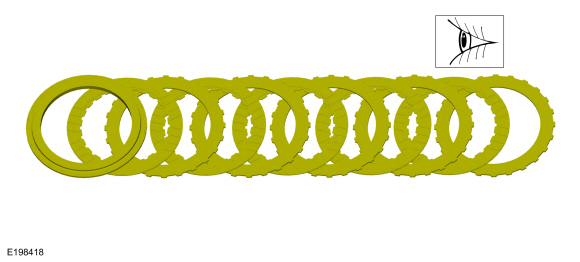
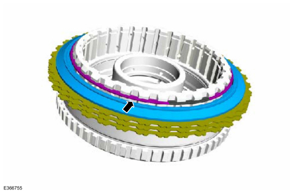
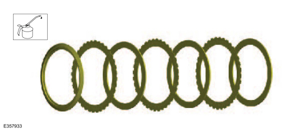
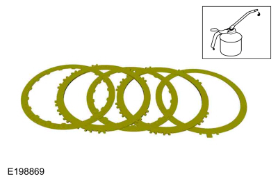
Soak the friction clutches in clean transmission fluid and install the following items.
-
A (1, 2, 3, 4, 5) clutch friction plate
-
A (1, 2, 3, 4, 5) clutch steel plate
-
A (1, 2, 3, 4, 5) clutch piston return spring
Material: Motorcraft® MERCON® ULV Automatic Transmission Fluid / XT-12-QULV (WSS-M2C949-A, ) (MERCON® ULV)
-
A (1, 2, 3, 4, 5) clutch friction plate
 |
-
Install the A (1, 2, 3, 4, 5) clutch pressure plate.
|
-
Install the A (1, 2, 3, 4, 5) clutch pressure plate snap ring.
|
-
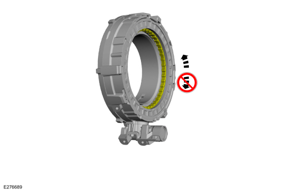
Test the hydraulic selectable one-way clutch operation.
The one-way clutch should rotate counter clock-wise and lock in the
clock-wise rotation, this is normal operation with no hydraulic pressure
applied.
 |
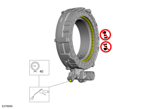
-
Test the hydraulic selectable one-way clutch operation
with 275 KPA (40 PSI) air applied, rotation in both directions are
locked, this is considered normal operation.
 |
-
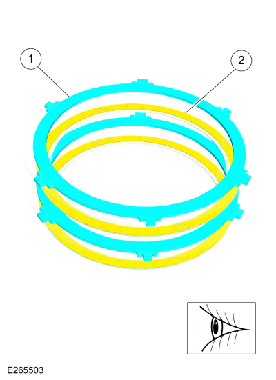
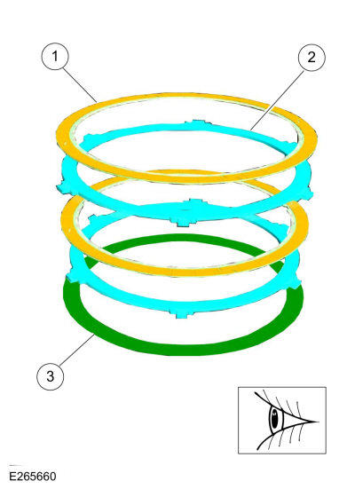
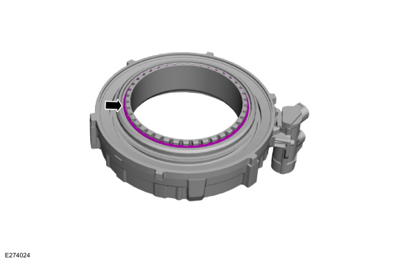
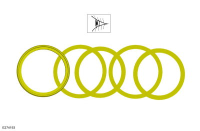
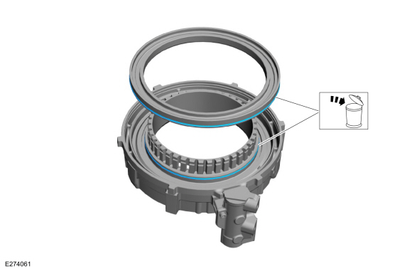
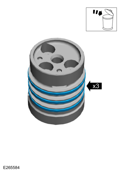
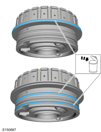
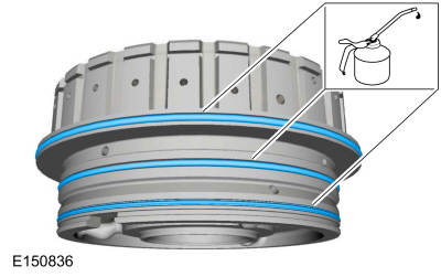
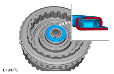
Remove and discard the 3 Teflon® seals.
 |
-
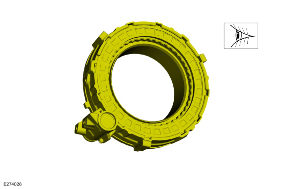
Clean and inspect the clutch support tower for damage. Install a new clutch support tower if damaged.
 |
-
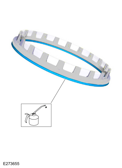
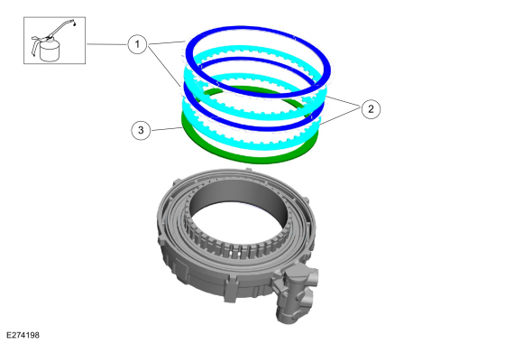
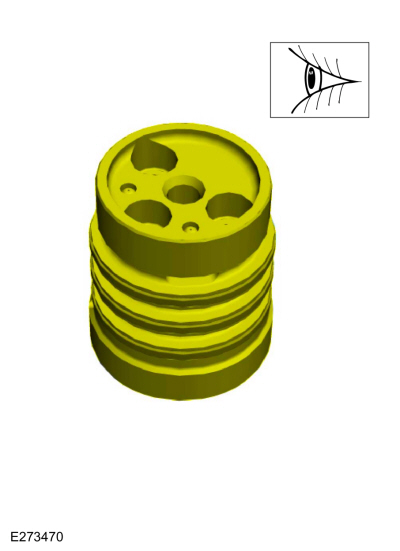
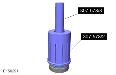
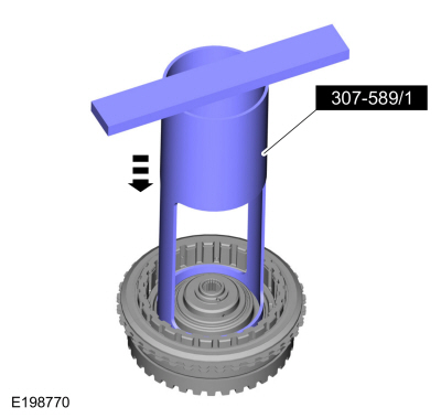
Install the special tool on the clutch support tower and
adjust the special tool to align the bottom edge of the tool with the
top edge of the bottom Teflon® seal groove.
Use Special Service Tool: 307-578 Input Shaft Support Seal Installer (Back Plate, Multiple rings).
 |
-
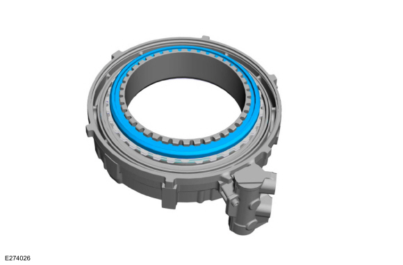
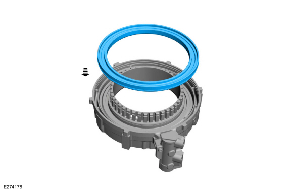
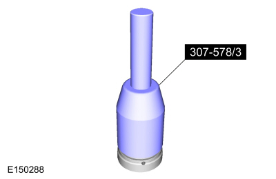
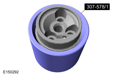
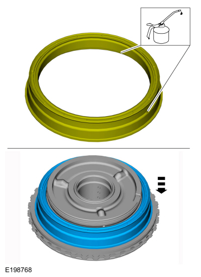
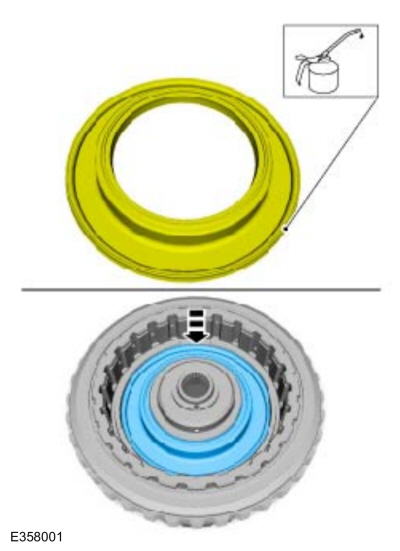
Install a new Teflon® seal on the special tool.
Use Special Service Tool: 307-578 Input Shaft Support Seal Installer (Back Plate, Multiple rings).
 |
-
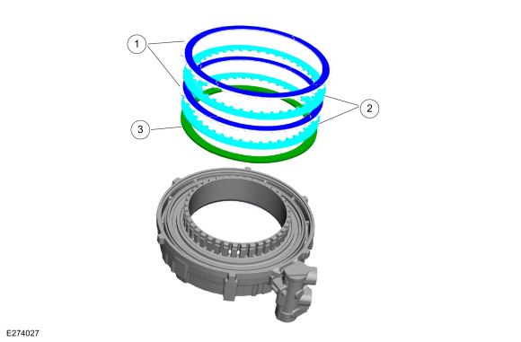
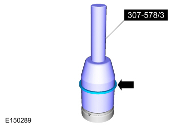
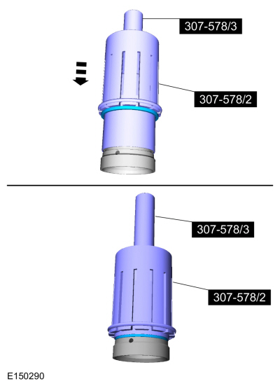
Install the special tool 307-578/2 over 307-578/3. Using
the special 307-578/2, slide the Teflon® seal over the clutch support
tower and into the groove.
Use Special Service Tool: 307-578 Input Shaft Support Seal Installer (Back Plate, Multiple rings).
 |
-
Remove tools and repeat steps for the other 2 Teflon® seals.
Use Special Service Tool: 307-578 Input Shaft Support Seal Installer (Back Plate, Multiple rings).
 |
-
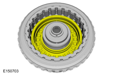
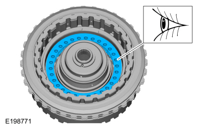
Install the special tool on the clutch support tower to size the 3 Teflon® seals.
Use Special Service Tool: 307-578 Input Shaft Support Seal Installer (Back Plate, Multiple rings).
 |
-
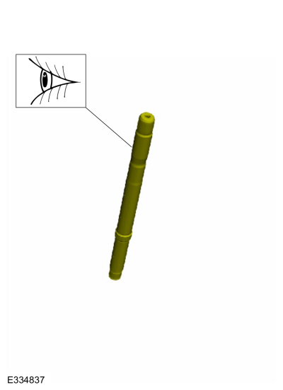
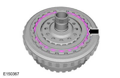
Remove the input shaft snap ring.
 |
-
Remove the input shaft.
 |
-
Inspect the input shaft bushing journal for damage, install new if necessary.
 |
-
Remove the E (5, 6, 7, 8) clutch hub.
 |
-
Remove the E (5, 6, 7, 8) clutch hub, No. 2 thrust bearing.
 |
-
Remove the E (5, 6, 7, 8) clutch snap ring.
 |
-
Remove the E (5, 6, 7, 8) clutch pressure plate and clutch assembly.
 |
-
Inspect the clutch plates for damage or excessive wear.
 |
-
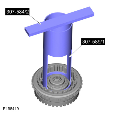
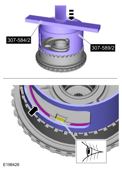
Install the special tools on the balance piston.
Use Special Service Tool: 307-584 2-6 Spring Compressor. , 307-589 Overdrive clutch and balance piston service set.
 |
-
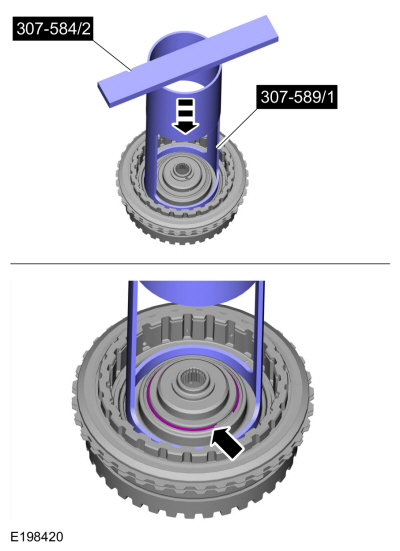
Using a press, compress the E (5, 6, 7, 8) clutch return spring and remove the snap ring.
Use Special Service Tool: 307-584 2-6 Spring Compressor. , 307-589 Overdrive clutch and balance piston service set.
Use the General Equipment: Hydraulic Press
 |
-
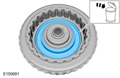
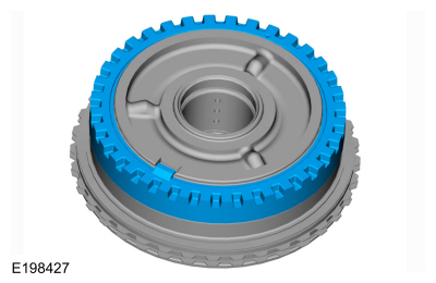
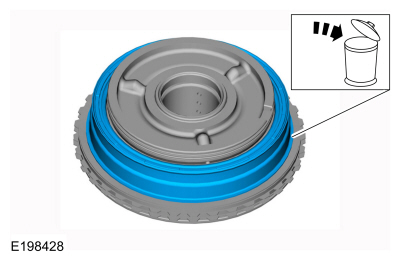
Remove and discard the balance piston.
 |
-
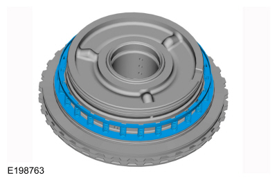
Remove the E (5, 6, 7, 8) piston return spring.
 |
-
Install the clutch support tower in the transmission case and install the clutch support tower bolts.
Torque: 124 lb.in (14 Nm)
 |
-
Remove the special tool.
Remove Special Service Tool: 307-578 Input Shaft Support Seal Installer (Back Plate, Multiple rings).
 |
-
Install the No. 1 thrust bearing.
 |
-
Position the B (4, 6, R)/E (5, 6, 7, 8) clutch assembly in the transmission case.
 |
-
Apply compressed air and remove the E (5, 6, 7, 8) clutch piston.
 |
-
Remove the B (4, 6, R)/E (5, 6, 7, 8) clutch assembly from the transmission case.
 |
-
Remove and discard the E (5, 6, 7, 8) clutch piston seals from the B (4, 6, R)/E (5, 6, 7, 8) clutch assembly.
 |
-
Remove and discard the seal from the E (5, 6, 7, 8) clutch piston.
 |
-
NOTICE: Only compress the B (4, 6, R) clutch piston return spring far enough to take the tension from the direct clutch cylinder off the snap ring. If the piston is compressed too far, the piston alignment tab may be broken off.
Install the special tools on the B (4, 6, R) clutch cylinder. Using a press, compress the B (4, 6, R) clutch piston return spring, and remove the snap ring.
-
Do not contact the B (4, 6, R)/E (5, 6, 7, 8) clutch
hub and shaft assembly with the B (4, 6, R) clutch cylinder.
-
Remove the snap ring.
Use Special Service Tool: 307-584 2-6 Spring Compressor. , 307-589 Overdrive clutch and balance piston service set.
Use the General Equipment: Hydraulic Press
-
Do not contact the B (4, 6, R)/E (5, 6, 7, 8) clutch
hub and shaft assembly with the B (4, 6, R) clutch cylinder.
 |
-
Remove the B (4, 6, R) clutch cylinder.
 |
-
Remove and discard the B (4, 6, R) clutch piston.
 |
-
NOTE: Note the position of the return spring for assembly. The flat side faces down.
Remove the B (4, 6, R) clutch piston return spring.
 |
-
Remove the B (4, 6, R) clutch snap ring.
 |
-
Remove the B (4, 6, R) clutch pressure plate and clutch pack.
 |
-
Inspect the clutch plates for damage or excessive wear.
 |
-
Remove and discard the B (4, 6, R) clutch piston seals.
 |
-
Clean and inspect the B (4, 6, R)/E (5, 6, 7, 8) clutch
assembly for damage or excessive wear, install new components as
necessary.
 |
-
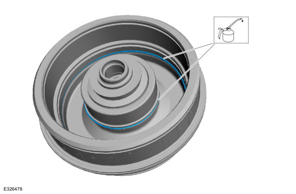
Install new B (4, 6, R) clutch piston seals and lubricate the seals with petroleum jelly.
Material: Petroleum Jelly
 |
-
Soak the B (4, 6, R) clutch pack in clean transmission fluid.
Material: Motorcraft® MERCON® ULV Automatic Transmission Fluid / XT-12-QULV (WSS-M2C949-A, ) (MERCON® ULV)
 |
-
Install the B (4, 6, R) clutch assembly and pressure plate.
|
-
Install the B (4, 6, R) clutch snap ring.
|
-
NOTE: Install the B (4, 6, R) clutch piston return spring with the flat side facing down.
Install the B (4, 6, R) clutch piston return spring.
 |
-
Lubricate a new B (4, 6, R) clutch piston with petroleum jelly and install the piston.
Material: Petroleum Jelly
 |
-
Install the B (4, 6, R) clutch cylinder.
|
-
NOTICE: Only compress the B (4, 6, R)/E (5, 6, 7, 8) clutch piston return spring far enough to take the tension from the B (4, 6, R)/E (5, 6, 7, 8) clutch cylinder off the snap ring. If the piston is compressed too far, the piston alignment tab may be broken off.
Install the special tools on the B (4, 6, R) clutch cylinder. Using a press, compress the B (4, 6, R) clutch piston return spring, and install the snap ring.-
Do not contact the B (4, 6, R)/E (5, 6, 7, 8) clutch
hub and shaft assembly with the B (4, 6, R) clutch cylinder.
-
Install the snap ring.
Use Special Service Tool: 307-584 2-6 Spring Compressor. , 307-589 Overdrive clutch and balance piston service set.
Use the General Equipment: Hydraulic Press
-
Do not contact the B (4, 6, R)/E (5, 6, 7, 8) clutch
hub and shaft assembly with the B (4, 6, R) clutch cylinder.
|
-
Install a new seal on the E (5, 6, 7, 8) clutch piston and lubricate the seal with petroleum jelly.
Material: Petroleum Jelly
 |
-
Install a new E (5, 6, 7, 8) clutch piston inner and outer seal and lubricate the seals with petroleum jelly.
Material: Petroleum Jelly
 |
-
Position the E (5, 6, 7, 8) clutch piston in place.
 |
-
Using the special tools, install the E (5, 6, 7, 8)
clutch piston into the B (4, 6, R)/E (5, 6, 7, 8) clutch assembly by
hand.
Use Special Service Tool: 307-589 Overdrive clutch and balance piston service set.
 |
-
NOTE: Holes face up on the E (5, 6, 7, 8) clutch piston return spring.
Install the E (5, 6, 7, 8) clutch piston return spring.
 |
-
Lubricate the seal on a new balance piston with petroleum jelly and position the piston in place.
Material: Petroleum Jelly
 |
-
Install the special tools on the balance piston.
Use Special Service Tool: 307-584 2-6 Spring Compressor. , 307-589 Overdrive clutch and balance piston service set.
|
-
Using a press, compress the E (5, 6, 7, 8) clutch return spring and install the snap ring.
Use Special Service Tool: 307-584 2-6 Spring Compressor. , 307-589 Overdrive clutch and balance piston service set.
Use the General Equipment: Hydraulic Press
|
-
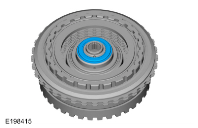
Install the No. 2 thrust bearing.
 |
-
Install the E (5, 6, 7, 8) clutch hub.
 |
-
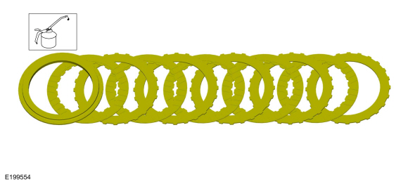
Soak the E (5, 6, 7, 8) clutch pack in clean transmission fluid.
Material: Motorcraft® MERCON® ULV Automatic Transmission Fluid / XT-12-QULV (WSS-M2C949-A, ) (MERCON® ULV)
 |
-
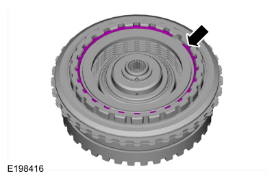
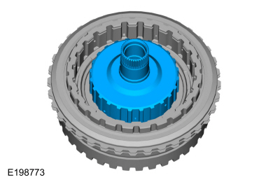
Install the E (5, 6, 7, 8) clutch pack.
 |
-
Install the E (5, 6, 7, 8) clutch pressure plate.
 |
-
Install the E (5, 6, 7, 8) clutch snap ring.
 |
-
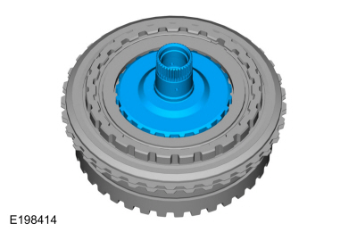
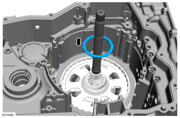
Install the input shaft.
|
-
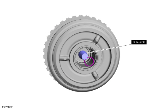
Using the special tool, hold the input shaft in place and install the snap ring.
Use Special Service Tool: 307-766 Installer, Input Shaft Snap Ring.
 |
-
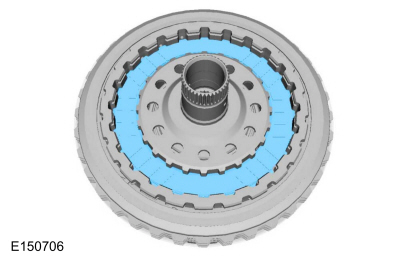
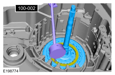
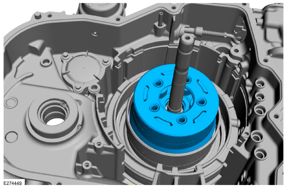
Position the B (4, 6, R)/E (5, 6, 7, 8) clutch assembly
in the transmission case, install the special tool or a dial indicator
and position the plunger on the E (5, 6, 7, 8) clutch pressure plate.
Zero out the micrometer and then move the plunger away from the plate.
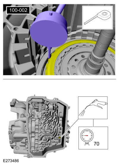
Use Special Service Tool: 100-002 (TOOL-4201-C) Holding Fixture with Dial Indicator Gauge.
Click here to view a video version of this procedure.

 |
-
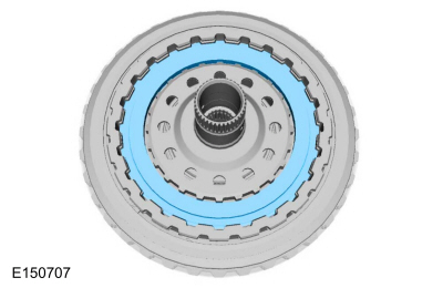
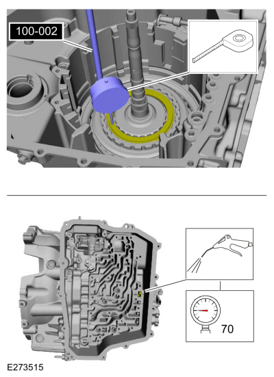
NOTE: The dial indicator plunger is positioned on the E (5, 6, 7, 8) clutch pressure plate.
Apply 482 kPa (70 psi) of air pressure to the E (5, 6, 7, 8) clutch piston port while recording the clutch pack clearance on the Dial Indicator. Measure and record in three places for an average reading. The clearance should be between 0.02 mm (0.0008 in) and 1.3 mm (0.053 in). If the clearance is out of range, check the E (5, 6, 7, 8) clutch pack for correct installation. If the E (5, 6, 7, 8) clutch pack is correctly installed, install a new E (5, 6, 7, 8) clutch pack.
Refer to: Specifications (307-01A Automatic Transmission - 8-Speed Automatic Transmission – 8F35/8F40, Specifications).
Use Special Service Tool: 100-002 (TOOL-4201-C) Holding Fixture with Dial Indicator Gauge.
 |
-
NOTE: The B (4, 6, R) clutch pressure plate travel is limited by the snap ring and the top of the center support legs. Placing the dial indicator on the pressure plate will not accurately measure total clutch pack clearance.
Position the plunger on the friction plate tooth of the top B (4, 6, R) clutch. Zero out the micrometer and then move the plunger away from the plate.
Apply 482 kPa (70 psi) of air pressure to the B (4, 6, R) clutch piston port while recording the clutch pack clearance on the Dial Indicator. Measure and record in three places for an average reading. The clearance should be between 0.20 mm (0.0079 in) and 1.91 mm (0.075 in). If the clearance is out of range, check the B (4, 6, R) clutch pack for correct installation. If the B (4, 6, R) clutch pack is correctly installed, install a new B (4, 6, R) clutch pack.
Refer to: Specifications (307-01A Automatic Transmission - 8-Speed Automatic Transmission – 8F35/8F40, Specifications).
Use Special Service Tool: 100-002 (TOOL-4201-C) Holding Fixture with Dial Indicator Gauge.
Click here to view a video version of this procedure.
 |
-
Remove the special tool, B (4, 6, R)/E (5, 6, 7, 8)
clutch assembly and the No. 1 B (4, 6, R)/E (5, 6, 7, 8) clutch assembly
thrust bearing.
Remove Special Service Tool: 100-002 (TOOL-4201-C) Holding Fixture with Dial Indicator Gauge.
 |
-
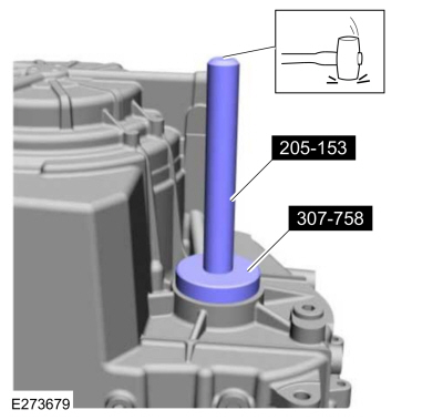
Assemble the special tools. Install a new LH halfshaft seal on the special tool.
Use Special Service Tool: 205-153 (T80T-4000-W) Handle. , 307-758 Installer, Axle Seal -FWD.
|
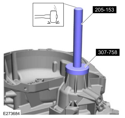
-
Using the special tools, install the new LH halfshaft seal in the transmission case.
Use Special Service Tool: 205-153 (T80T-4000-W) Handle. , 307-758 Installer, Axle Seal -FWD.
 |
-
Install the park pawl guide and a new roll pin.
Use the General Equipment: Punch
 |
-
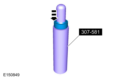
Install a new manual control shaft seal on the special tool.
Use Special Service Tool: 307-581 Manual lever seal installer.
 |
-
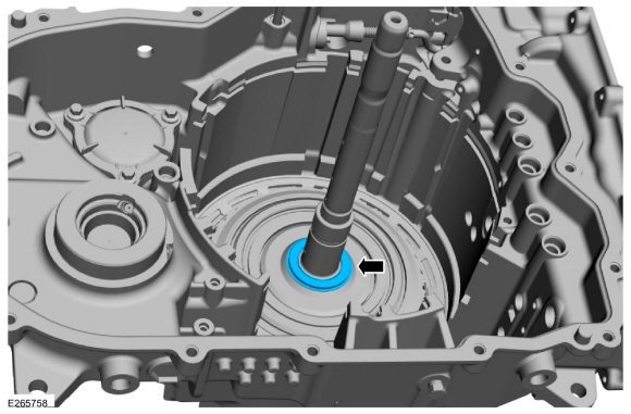
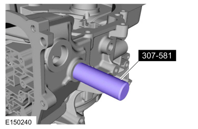
Using the special tool, install the new manual control shaft seal in the transmission case.
Use Special Service Tool: 307-581 Manual lever seal installer.
 |
-
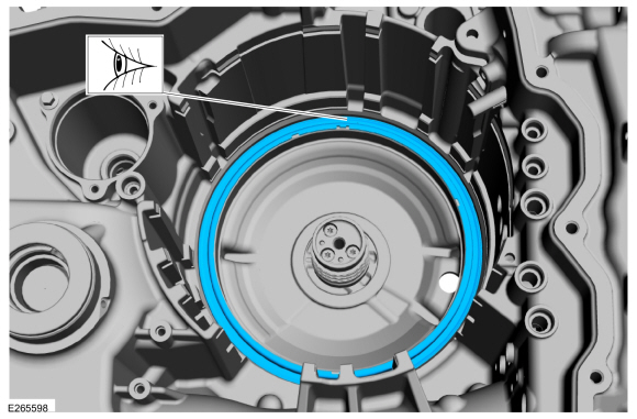
Lubricate the seals on the C (3, 7) clutch piston with petroleum jelly.
Material: Petroleum Jelly
 |
-
NOTE: Note the location of the bleed hole. Must be installed at the 12 o'clock position.
Install the C (3, 7) clutch piston.
 |
-
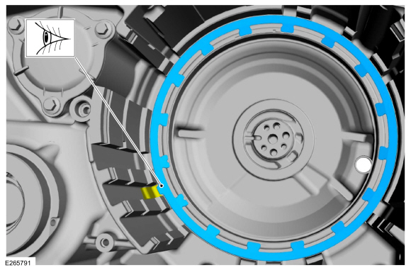
NOTE: Note the location of the location tab on the return spring.
Install the C (3, 7) clutch piston return spring.
 |
-
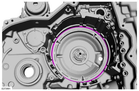
NOTE: Note the location of the snap ring gap for assembly.
Position the C (3, 7) clutch piston return spring snap ring.
|
-
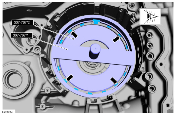
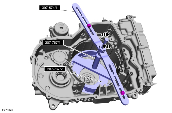
NOTE: The piston return spring must stay centered or it will become trapped in the snap ring groove.
Carefully position the special tool into the transmission while keeping the C (3, 7) clutch piston return spring and snap ring centered.
Use Special Service Tool: 307-767 Compressor, 3-8 Spring.
 |
-
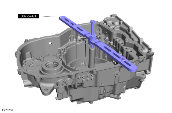
Install the special tool on the transmission case.
Use Special Service Tool: 307-574 Forward Clutch Spring Compressor.
 |
-
NOTICE: Be sure the return spring is centered or it can bind on the snap ring groove and cause damage to the transmission case.
Using the special tools, install the C (3, 7) clutch snap ring in the groove.
Use Special Service Tool: 307-574 Forward Clutch Spring Compressor. , 307-767 Compressor, 3-8 Spring.
 |
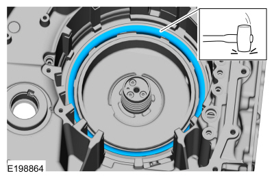
-
Verify the C (3, 7) clutch piston return spring snap ring is fully seated.
 |
-
Install the C (3, 7) clutch apply ring. Tap the ring in place.
 |
-
Soak the C (3, 7) clutch assembly in clean transmission fluid.
Material: Motorcraft® MERCON® ULV Automatic Transmission Fluid / XT-12-QULV (WSS-M2C949-A, ) (MERCON® ULV)
 |
-
NOTE: Do not air check the C (3, 7) clutch pack, snap ring groove damage may occur.
NOTE: Wave spring is installed prior to steel and friction plates.
Install the C (3, 7) clutch assembly, temporarily reversing the top friction and steel plates for the clutch stack-up measurement.
-
Friction plate
-
Steel plate
-
Friction plate
Click here to view a video version of this procedure.
 |
-
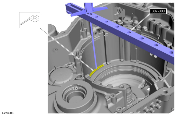
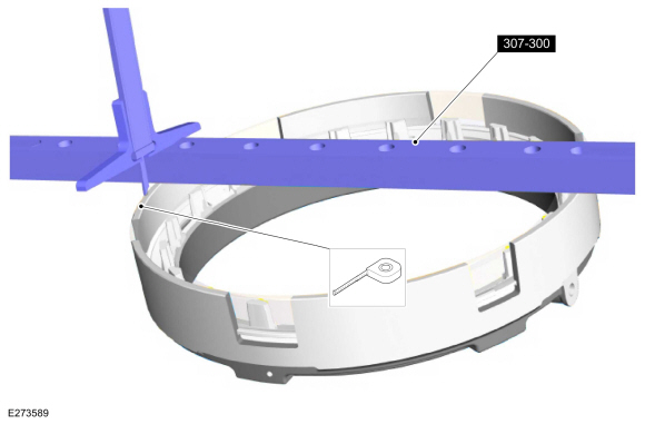
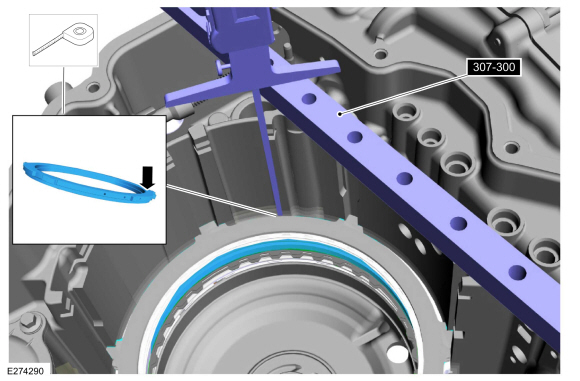
Using the special tool and a 7-8" (375-400mm) depth gauge, zero depth gauge on the case step.
Use Special Service Tool: 307-300 Gauge Bar, Shim Selection.
 |
-
Using the special tool and a 7-8" (375-400mm) depth
gauge, measure and record as measurement A, the C (3, 7) clutch pack at 3
different points and average the 3 distances.
Use Special Service Tool: 307-300 Gauge Bar, Shim Selection.
 |
-
Remove the C (3, 7) clutch pack.
 |
-
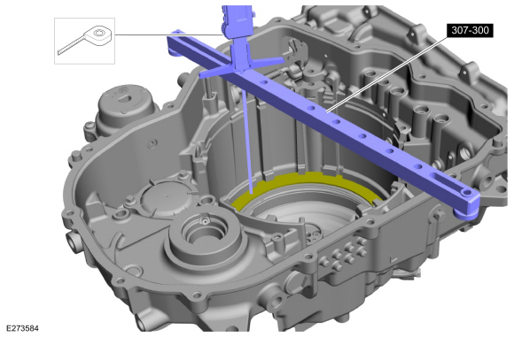
Using a depth gauge, zero the gauge on the tall face
of the pressure plate, measure and record as measurement B, the outside
step of the pressure plate at 3 different points and average the 3
distances.
Use Special Service Tool: 307-300 Gauge Bar, Shim Selection.
 |
-
Subtract measurement B from measurement A The clearance
should be between 0.01 mm (0.0003 in) and 1.85 mm (0.0728 in). If the
clearance is out of range, check the C (3, 7) clutch pack for correct
installation. If the C (3, 7) clutch pack is correctly installed,
install a new clutch pack.
Description Reading Measurement A Measurement B Subtract measurement B from measurement A and check to see if it is within range of 0.01 mm (0.0003 in) and 1.85 mm (0.0728 in)
-
NOTICE: Be sure to install the No. 1 thrust bearing with the flat side facing up or damage to the transmission can occur.
Install the No. 1 thrust bearing.
 |
-
Install the B (4, 6, R)/E (5, 6, 7, 8) clutch assembly.
 |
-
NOTICE: Be sure to install the No. 3 thrust bearing with the flat side facing down or damage to the transmission can occur.
Install the No. 3 thrust bearing with the flat side facing down.
 |
-
Install the B (4, 6, R)/C (3, 7) clutch hub and reaction sun gear assembly.
 |
-
NOTE: Wave spring is installed prior to steel and friction plates. When the C (3, 7) clutch is correctly installed, a friction plate is on top.
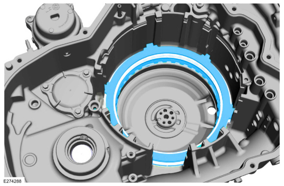
Install the C (3, 7) clutch pack in the transmission case.
-
Friction plate
-
Steel plate
-
Friction plate
 |
-
Install the C (3, 7)/F (2, 8) clutch pressure plate.
 |
-
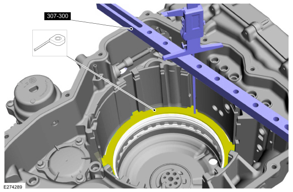
Using the special tool and a depth gauge, zero the depth
gauge on the top of the F (2, 8) clutch piston housing.
Use Special Service Tool: 307-300-01 Adapter for 307-300.
Click here to view a video version of this procedure.
 |
-
Using the special tool and a depth gauge zeroed on the
piston housing, measure and record as measurement A to the top of the F
(2, 8) clutch piston.
Use Special Service Tool: 307-300 Gauge Bar, Shim Selection.
 |
-
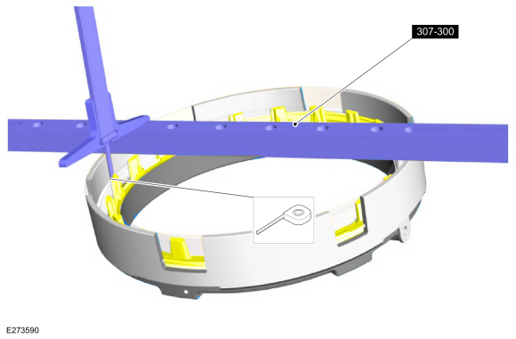
NOTE: The B (4, 6, R)/E (5, 6, 7, 8) clutch is not shown for clarity.
Install the F (2, 8) clutch pack.
 |
-
NOTE: The B (4, 6, R)/E (5, 6, 7, 8) clutch is not shown for clarity.
Using the special tool and a depth gauge, zero depth gauge on the top seperator plate.
Use Special Service Tool: 307-300-01 Adapter for 307-300.
 |
-
NOTE: The B (4, 6, R)/E (5, 6, 7, 8) clutch is not shown for clarity.
Using the special tool and a depth gauge, measure and record as measurement B to the C (3, 7)/F (2, 8) clutch pressure plate, at 3 different points and average the 3 distances
 |
-
Subtract measurement B from measurement A The clearance
should be between 0.45 mm (0.018 in) and 1.43 mm (0.056 in). If the
clearance is out of range, check the C (3, 7) clutch pack for correct
installation. If the C (3, 7) clutch pack is correctly installed,
install a new clutch pack.
Description Reading Measurement A Measurement B Subtract measurement B from measurement A and check to see if it is within range of 0.45 mm (0.018 in) and 1.43 mm (0.056 in).
-
Install the No. 4 thrust bearing onto the B (4, 6, R)/C (3, 7) clutch shell.
|
-
Install the E (5, 6, 7, 8)/F (2, 8) hub assembly.
|
-
NOTE: Install the No. 5 thrust bearing with tabs facing down.
Install the No. 5 thrust bearing onto the E (5, 6, 7, 8)/F (2, 8) hub assembly.
 |
-
Install the S-3 sun gear onto the E (5, 6, 7, 8) clutch hub.
|
-
Install the F (2, 8) clutch piston assembly.
|
-
Install the reaction/overdrive planetary carrier.
 |
-
Install the No. 7 and No. 8 thrust bearings onto the reaction/overdrive planetary assembly.
-
No. 7 thrust bearing
-
No. 8 thrust bearing
-
No. 7 thrust bearing
 |
-
Install the input planetary carrier.
 |
-
Install the No. 9 and the No. 10 thrust bearings and the input sun gear into the input carrier.
-
No. 10 thrust bearing
-
Input sun gear
-
No. 9 thrust bearing
-
No. 10 thrust bearing
|
-
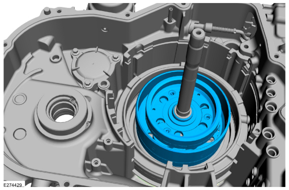
Install the output planetary carrier.
 |
-
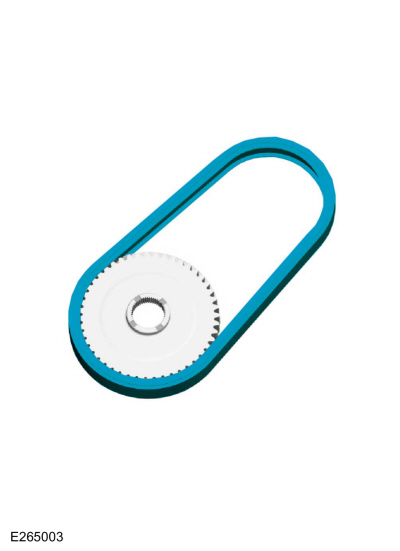
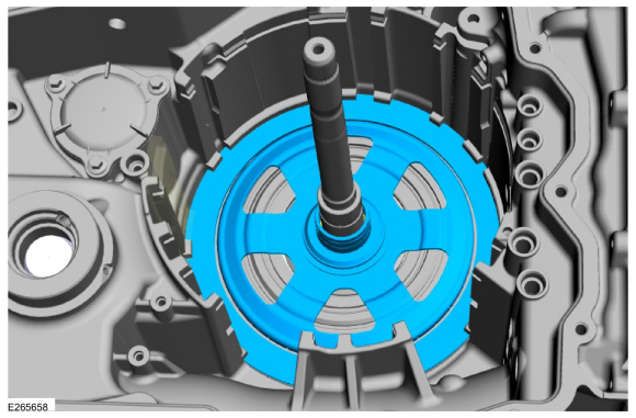
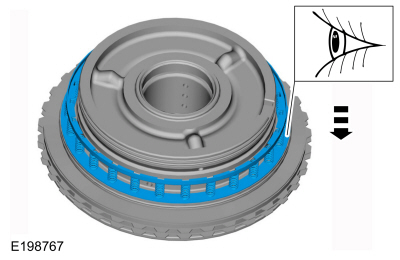
Install the hydraulic selectable one-way clutch assembly.
|
-
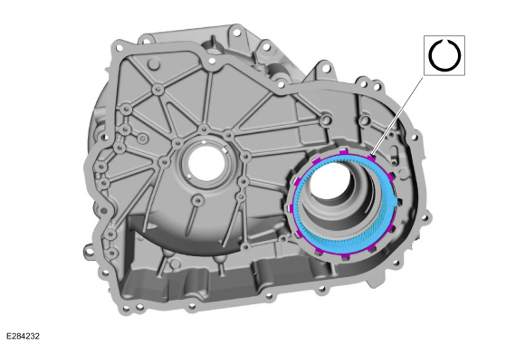
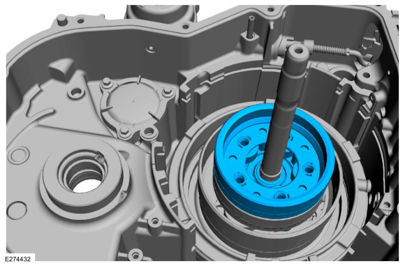
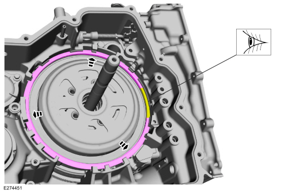
Install the hydraulic selectable one-way clutch assembly
snap ring with the flat side down and the gap at the 3 o'clock
position. Verify the hydraulic selectable one-way clutch assembly snap
ring is fully seated.
 |
-
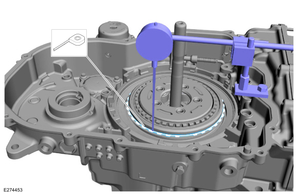
Using the special tools, zero the micrometer on the top
of the A (1, 2, 3, 4, 5) clutch friction plate tooth and then move the
micrometer away from the plate.
Use the General Equipment: Dial Indicator
Click here to view a video version of this procedure.
 |
-
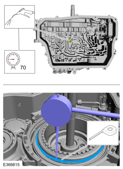
Apply 482 KPA (70 psi) of air pressure to the A (1, 2,
3, 4, 5) clutch port, measure and record the distance to the friction
plate tooth in three places for an average reading. The clearance should
be between 0.59 mm (0.023 in) and 1.93 mm (0.075 in). If the clearance
is out of range, check the A (1, 2, 3, 4, 5) clutch pack for correct
installation. If the A (1, 2, 3, 4, 5) clutch pack is correctly
installed, install a new A (1, 2, 3, 4, 5) clutch pack.
Use the General Equipment: Dial Indicator
 |
-
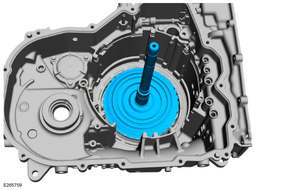
Install the output sun gear shell.
 |
-
NOTE: The No. 12 thrust bearing is installed with the flange side down.
Install the following items.
-
No. 15 thrust bearing
-
No. 12 thrust bearing
-
No. 15 thrust bearing
|
-
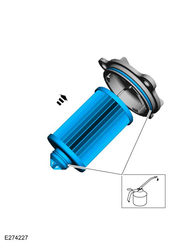
Install a new transmission fluid filter and seal to the
cover. Lubricate the seal on the transmission fluid filter and the cover
with petroleum jelly.
Material: Petroleum Jelly
 |
-
Install the transmission fluid filter, cover and the bolts.
Torque: 97 lb.in (11 Nm)
|
-
Install the transmission fluid baffle and the bolts.
Torque: 97 lb.in ( 11 Nm)
|
-
Install a new chain snubber seal and lubricate with petroleum jelly.
Material: Petroleum Jelly
 |
-
Install the chain snubber assembly into the case.
 |
-
Install the park pawl.
|
-
Install the park pawl spring and pin.
|
-
Install new clutch feed seals.
 |
-
Verify the No. 12 thrust bearing is in place and install the output drive hub assembly.
|
-
NOTE: The No. 13 thrust bearing is installed with the flat side down.
Install the following items.
-
Plastic thrust bearing
-
No. 13 thrust bearing
-
Plastic thrust bearing
|
-
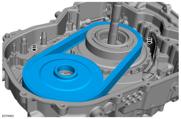
Simultaneously install the driven sprocket and chain.
 |
-
Install the differential sun gear.
|
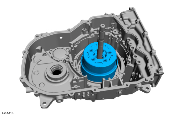
-
NOTE: Verify the bearing race is inside of the differential assembly.
Install the No. 16 thrust bearing.
|
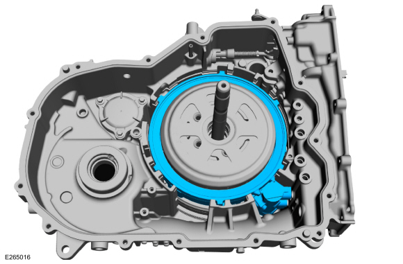
-
Install the differential assembly.
|
-
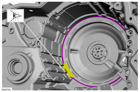
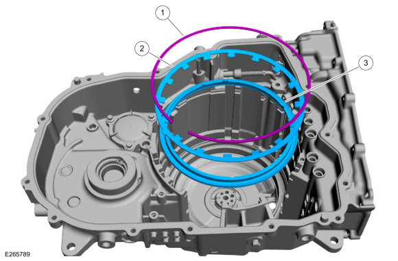
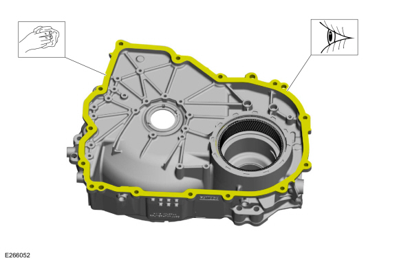
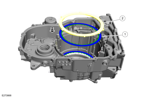
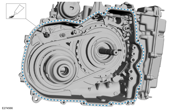
NOTE: Be sure the sealing surfaces of the torque converter housing and the transmission housing are free of any residue before applying silicone.
Apply silicone to the sealing surface of the transmission case.
Material: Motorcraft® Ultra Silicone Sealant / TA-29 (WSS-M4G323-A8)
 |
-
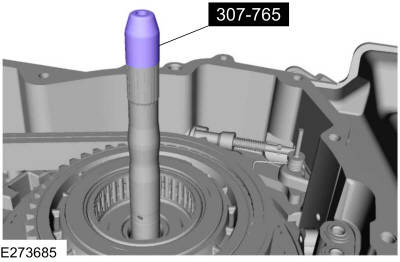
Install the special tool on the input shaft.
Use Special Service Tool: 307-765 Protector, Turbine Seal.
 |
-
Install the torque converter housing onto the transmission case.
|
-
NOTE: Before and after final torque, verify the input shaft rotates. If not, remove converter housing and check for improper assembly.
NOTE: Note the location of the stud bolts.
Install the torque converter housing bolts and stud bolts.
Torque: 18 lb.ft (25 Nm)
|
-
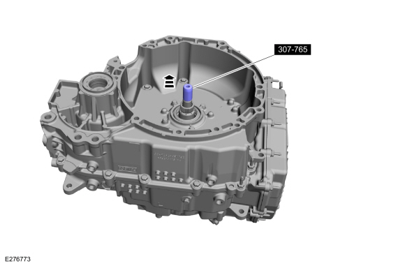
Remove the special tool from the input shaft.
Use Special Service Tool: 307-765 Protector, Turbine Seal.
 |
-
Install the TSS/ISSA (Turbine Shaft speed/Intermediate Shaft Speed) sensor and the bolt.
Torque: 97 lb.in (11 Nm)
|
-
Install the OSS sensor, the bolt and the wire harness clip.
Torque: 97 lb.in (11 Nm)
|
-
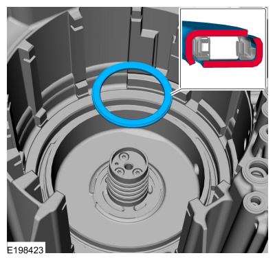
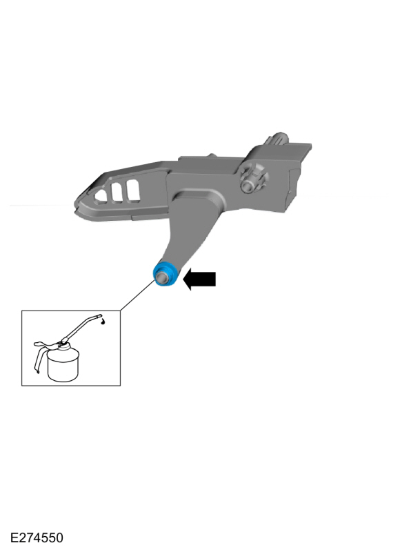
Inspect and lubricate the O-ring.
Material: Petroleum Jelly
 |
-
Install the transmission fluid transfer pipe and the bolt.
Torque: 97 lb.in (11 Nm)
 |
-
NOTE: One hydraulic passage is blank and doesn't require a seal.
Install the A (1, 2, 3, 4, 5), C (3, 7), F (2, 8), and the D (SOWC) clutch main control valve body case seals.
|
Vehicles with Cable Shift
-
Install the following items and a new roll pin.
-
Manual valve detent lever and park pawl actuator rod as an assembly
-
TR sensor
-
Manual control shaft and lever
-
Roll pin
Use the General Equipment: Punch
-
Manual valve detent lever and park pawl actuator rod as an assembly
 |
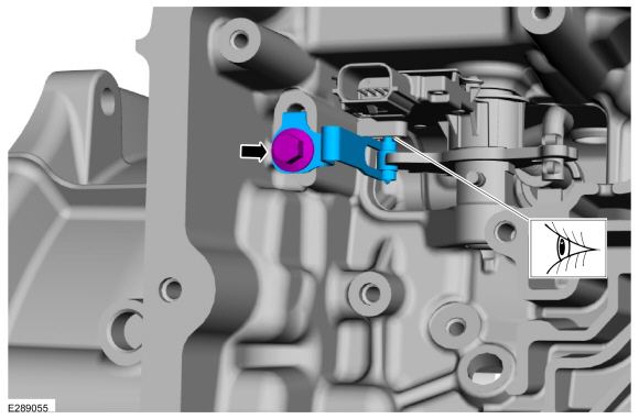
-
NOTE: Make sure the detent spring pin roller engages the transmission range sensor.
Install the TR sensor detent spring and the bolt.
Torque: 106 lb.in (12 Nm)
 |
-
NOTE: Note the location of the short and long main control valve body bolts. Tighten the bolts in the sequence shown.
Install the main control valve body and the bolts.
Torque:
Stage 1: 44 lb.in (5 Nm)
Stage 2: 62 lb.in (7 Nm)
 |
Vehicles with Park-By-Wire
-
Install the following items and a new roll pin.
-
TR sensor and park pawl actuator rod as an assembly
-
Manual control shaft and lever
-
Roll pin
Use the General Equipment: Punch
-
TR sensor and park pawl actuator rod as an assembly
 |
-
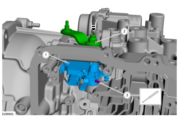
NOTE: Make sure the transmission range sensor is aligned with the park-by-wire support bracket.
Position the park-by-wire support bracket, the spring and install the bolt.
Torque: 97 lb.in (11 Nm)
 |
-
NOTE: Make sure the park lock valve is aligned with the parking pawl linkage during main control valve body installation.
NOTE: Note the location of the short and long main control valve body bolts. Tighten the bolts in the sequence shown.
Install the main control valve body and the bolts.
Torque:
Stage 1: 44 lb.in (5 Nm)
Stage 2: 62 lb.in (7 Nm)
 |
All vehicles
-
Install the wiring harness connector bolts.
Torque: 71 lb.in (8 Nm)
 |
-
Connect and lock the TR sensor electrical connector.
 |
-
Connect and lock the OSS sensor electrical connector.
 |
-
Install the main control cover gasket.
 |
-
Install the main control cover and the stud bolts.
Torque: 80 lb.in (9 Nm)
|
-
Install and lubricate the start/stop accumulator O-rings with petroleum jelly.
Material: Petroleum Jelly
 |
-
NOTE: To prevent O-ring damage, fully seat the start/stop accumulator before installing the bolts.
Install the start/stop accumulator, the bolts and the studbolt.
Torque: 18 lb.ft (25 Nm)
|
-
NOTE: The special tool must remain installed until the torque converter is installed.
Remove the special tool.
Use Special Service Tool: 307-764 Installer/Sizer, Stator Teflon Seal.
 |
-
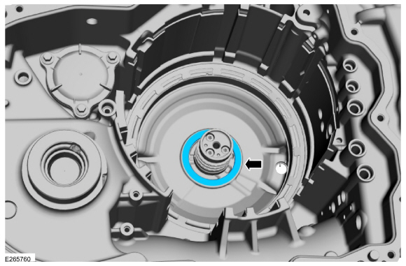
NOTICE: The torque converter is heavy. Be careful not to drop it or damage will result.
Using the special tools, install the torque converter.
Use Special Service Tool: 307-091 Handle, Torque Converter.
 |
-
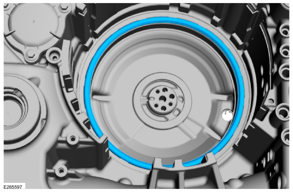
Install the special tool.
Install Special Service Tool: 307-566 Retainer, Torque Converter.
 |
-
Remove the transmission from the bench-mounted holding fixture and the special tool.
Remove Special Service Tool: 307-003 (T57L-500-B) Holding Fixture, Transmission.
Use Special Service Tool: 307-769 Fixture, Bench Mount.
|
 Overhaul - Main Control Valve Body
Special Tool(s) /
General Equipment
Flat Headed Screw Driver
Materials
Name
Specification
Motorcraft® MERCON® ULV Automatic Transmission FluidXT-12-QULV
WSS-M2C949-A, MERCON® ULV
Main Control Valve Body and Solenoid Body
Unlock and disconnect the transmission shift solenoid electrical connectors and the TFT
sensor electrical connector...
 Disassembly - Transmission
Disassemble the transmission.
Refer to: Transmission (307-01A Automatic Transmission - 8-Speed Automatic Transmission – 8F35/8F40, Overhaul)...
Other information:
Lincoln Corsair 2020-2026 Service Manual: General Procedures - Rear Camber Adjustment
Special Tool(s) / General Equipment Wheel Alignment System Adjustment NOTICE: Suspension fasteners are critical parts that affect the performance of vital components and systems. Failure of these fasteners may result in major service expense...
Lincoln Corsair 2020-2026 Owners Manual: Warning Lamps and Indicators
The following warning lamps and indicators alert you to a vehicle condition that may become serious. Some lamps illuminate when you start your vehicle to make sure they work. If any lamps remain on after starting your vehicle, refer to the respective system warning lamp for further information...
Categories
- Manuals Home
- 1st Generation Lincoln Corsair Owners Manual
- 1st Generation Lincoln Corsair Service Manual
- Child Safety Locks
- Interior Lamps
- Normal Scheduled Maintenance
- New on site
- Most important about car
Keyless Starting
Note: The keyless starting system may not function if the key is close to metal objects or electronic devices such as cellular phones.
Note: A valid key must be located inside your vehicle to switch the ignition on and start the engine.
Ignition Modes