Lincoln Corsair: Suspension System - General Information / General Procedures - Ride Height Measurement
Special Tool(s) / General Equipment
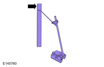
| Surface Gauge |
Check
NOTE: Make sure that the vehicle is positioned on a flat, level surface and the tires are inflated to the correct pressure. Vehicle should have a full tank of fuel.
-
Before measuring ride height check:
-
Tires are inflated to the correct pressure.
-
Vehicle should have a full tank of fuel.
-
All fluids at proper levels.
-
No cargo inside the cab or bed.
-
Inspect for aftermarket equipment. Check for
aftermarket changes to the steering, suspension, wheel and tire
components (such as competition, heavy duty, etc.).
-
Tires are inflated to the correct pressure.
-
Jounce front and rear suspension vigorously to allow the vehicle to settle.
Ride Height Measurement — Front
-
-
Ride height = 3-2
-
Measure the distance between the flat level
surface and the center of the lower arm forward bolt (measurement 2).
Use the General Equipment: Surface Gauge
-
Measure the distance between the flat level
surface and the center of the ball joint bolt (measurement 3).
Use the General Equipment: Surface Gauge
-
Ride height = 3-2
 |
-
With the surface gauge positioned on a flat, level
surface, record the measurement of the surface gauge position
(measurement 2) and (measurement 3).
Use the General Equipment: Surface Gauge
 |
-
Subtract measurement 2 from measurement 3 to obtain the front ride height.
Ride Height Measurement — Rear
-
-
Ride height = 3-2
-
Measurement 3
-
Measurement 2
Use the General Equipment: Surface Gauge
-
Ride height = 3-2
 |
-
Measure the distance between the flat level surface
and the center of the toe link inboard cam bolt (measurement 2).
Use the General Equipment: Surface Gauge
-
Measure the distance between the flat level surface
and the center of the toe link outboard bolt (measurement 3).
Use the General Equipment: Surface Gauge
-
Subtract measurement 2 from measurement 3 to obtain the rear ride height.
Refer to: Specifications (204-00 Suspension System - General Information, Specifications).
 General Procedures - Rear Toe Adjustment
Special Tool(s) /
General Equipment
Wheel Alignment System
Adjustment
NOTICE:
Do not use any tools or equipment to move the wheel and tire
assembly or suspension components while checking for relative movement...

Other information:
Lincoln Corsair 2020-2026 Owners Manual: General Information
Note: Occasional brake noise is normal. If a metal-to-metal, continuous grinding or continuous squeal sound is present, the brake linings may be worn-out and an authorized dealer should check them. If the vehicle has continuous vibration or shudder in the steering wheel while braking, an authorized dealer should check your vehicle. Note: Brake dust may accumulate on the wheels, even under ..
Lincoln Corsair 2020-2026 Service Manual: Description and Operation - Handles, Locks, Latches and Entry Systems - Overview
Overview NOTE: The Phone As A Key feature can also be used to lock/unlock the vehicle. Refer to section 419-01C for information regarding this feature. The power lock/unlock feature locks or unlocks the doors upon a customer request from a door lock control switch, the keyless entry keypad, the passive entry system or a RKE transmitter. Each door can also be locked manually using the m..
Categories
- Manuals Home
- 1st Generation Lincoln Corsair Owners Manual
- 1st Generation Lincoln Corsair Service Manual
- Memory Function
- Interior Lamps
- Auto Hold (IF EQUIPPED)
- New on site
- Most important about car
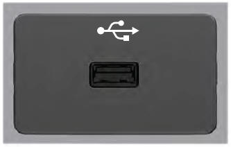
USB Port
WARNING: Driving while distracted can result in loss of vehicle control, crash and injury. We strongly recommend that you use extreme caution when using any device that may take your focus off the road. Your primary responsibility is the safe operation of your vehicle. We recommend against the use of any hand-held device while driving and encourage the use of voice-operated systems when possible. Make sure you are aware of all applicable local laws that may affect the use of electronic devices while driving.
USB A