Lincoln Corsair: Wheels and Tires / Diagnosis and Testing - Wheels and Tires
Preliminary Inspection
-
Verify the customer concern by carrying out a road test on a
smooth road. If any vibrations are apparent, Refer to the Symptom
Chart: NVH.
-
To maximize tire performance, inspect for signs of incorrect
inflation and uneven wear, which may indicate a need for balancing,
rotation or front suspension alignment.
-
Correct tire pressure and driving techniques have an
important influence on tire life. Heavy cornering, excessively rapid
acceleration and unnecessary sharp braking increase tire wear.
Replacement tires must follow the recommended:
- tire sizes.
- speed rating.
- load range.
- tire construction type.
The use of any other tire/wheel size, load range or type can seriously affect:
- ride.
- handling.
- speedometer/odometer calibration.
- vehicle ground clearance.
- tire clearance between the body and chassis.
- wheel bearing life.
- braking performance.
New wheels need to be installed when the vehicle wheels:
- are bent.
- are cracked.
- are dented.
- are heavily corroded.
- are leaking.
- have elongated wheel hub bolt holes.
- have excessive lateral or radial runout.
It is mandatory to use only the tire sizes recommended on the tire label located on the driver door or door pillar attached to the vehicle. Larger or smaller tires can damage the vehicle, affect durability and require changing the speedometer calibration. Make sure wheel size and offset match the original wheel specification for the tire in use.
Inspect the tires for signs of uneven wear. the following descriptions to identify the type of wear.
Check the tires for:
- cuts.
- stone bruises.
- abrasions.
- blisters.
- embedded objects.
Check the valve stems for:
- cracks.
- cuts.
Install a new valve stem when damage is found or anytime a new tire or wheel is installed.
Tread wear indicators are molded into the bottom of the tread grooves. Install a new tire when the indicator bands become less than measurement 1.6mm (2/32 inch).
Tire Wear
Tire wear is commonly defined as a loss of tread depth. Tire tread wear occurs due to friction with the contact surface (road/pavement). The tread should wear down uniformly all the way around the circumference of the tire and all the way across the tread face. When this does not occur, the tire may have abnormal/incorrect wear.
Normal Tire Wear
Normal tire wear is identified as even wear around and across the tread. Because there are many factors (driving style, road surfaces, type of vehicle, type of tire) that can affect tire wear, there is no absolute mileage expectation for a normal wear condition. A tire is considered worn-out when the tread has worn to the level of the tread-wear indicators.
Abnormal/Incorrect Tire Wear
Abnormal/incorrect tire wear is identified as tire wear that is not even around or across the tread and that creates performance-related issues.
Abnormal/incorrect wear can be caused by numerous factors, some of which include driving style (aggressive, passive), climate (hot, cold), road conditions, vehicle loading and maintenance (correct tire pressure, rotation intervals and balance). It is important to determine the root cause of wear on a vehicle before carrying out repair. Tires exhibiting abnormal/incorrect tire wear may still be serviceable provided that the minimum tread depth is greater than 1.6mm (2/32 inch) and the tire is not causing a vehicle performance (noise/vibration) concern.
Inner Edge/Shoulder Wear
Inner edge (or shoulder) wear occurs on the inside edge of the tire and is usually caused by excessive toe out and/or excessive negative camber. If the tread depth of the outer shoulder is at least 50% greater than the tread depth of the inner shoulder, the tire is experiencing inner edge/shoulder wear. To determine whether tires have this type of wear, visually inspect the tires. In some instances, it may be necessary to measure the tread depth of each rib and compare it to that of the shoulder.
NOTE: Right Front tire shown, others similar.
Outer Edge/Shoulder Wear
Outer edge (or shoulder) wear occurs on the outside edge of the tire and is usually caused by excessive toe in and/or excessive positive camber. If the tread depth of the inner shoulder is at least 50% greater than the tread depth of the outer shoulder, the tire is experiencing outer edge/shoulder wear. To determine whether tires have this type of wear, visually inspect the tires. In some instances, it may be necessary to measure the tread depth of each rib and compare it to that of the shoulder.
NOTE: Right Front tire shown, others similar.
Heel/Toe Wear
Heel/toe wear (also known as feathering) occurs along the outside or inside edge/shoulder of the tire. To determine whether tires have this type of wear, visually inspect the tires in both the inside and outside shoulder ribs. In some instances, it may be necessary to measure the difference in tread depth of leading versus trailing edge of each lug in the inside and outside shoulder rib.
Diagonal Wear
Diagonal wear occurs diagonally across the tread area and around the circumference of the tire. To determine whether tires have this type of wear, visually inspect the tires to determine if the wear pattern runs diagonally across the tread and around the circumference of the tire. In some instances, the difference in tread depth along the diagonal wear pattern may need to be measured.
Symptom Chart(s)
Diagnostics in this manual assume a certain skill level and knowledge of Ford-specific diagnostic practices.
REFER to: Diagnostic Methods (100-00 General Information, Description and Operation).
 WARNING:
Vehicle may have multiple drive wheels. Do not use engine to
power the driveline unless all drive wheels are elevated off the
ground. Drive wheels in contact with ground could cause unexpected
vehicle movement. Failure to follow this instruction may result in
serious personal injury.
WARNING:
Vehicle may have multiple drive wheels. Do not use engine to
power the driveline unless all drive wheels are elevated off the
ground. Drive wheels in contact with ground could cause unexpected
vehicle movement. Failure to follow this instruction may result in
serious personal injury.
Symptom Chart: Tire Wear
| Condition | Actions |
|---|---|
| Inner edge/shoulder wear | GO to Pinpoint Test A |
| Outer edge/shoulder wear | GO to Pinpoint Test B |
| Heel/toe wear | GO to Pinpoint Test C |
| Diagonal wear | GO to Pinpoint Test D |
Symptom Chart: NVH
Diagnostics in this manual assume a certain skill level and knowledge of Ford-specific diagnostic practices.
REFER to: Diagnostic Methods (100-00 General Information, Description and Operation).
NOTE: If equipped, the Lane Keeping System (LKS) can interfere with accurate NVH diagnostics. Disable the Lane Keeping System (LKS) before test driving the vehicle to diagnose NVH concerns. For information on disabling the Lane Keeping System (LKS), refer to the Owner's Literature.
NVH
symptoms should be identified using the diagnostic tools that are
available. For a list of these tools, an explanation of their uses and a
glossary of common terms,
REFER to: Noise, Vibration and Harshness (NVH) (100-04 Noise, Vibration and Harshness, Diagnosis and Testing).
Since it is possible any one of multiple systems may be the cause of a
symptom, it may be necessary to use a process of elimination type of
diagnostic approach to pinpoint the responsible system. If this is not
the causal system for the symptom, REFER to: Noise, Vibration and
Harshness (NVH) (100-04 Noise, Vibration and Harshness, Diagnosis and
Testing).
for the next likely system and continue diagnosis.
| Condition | Actions |
|---|---|
| Wobble or shimmy | GO to Pinpoint Test E |
| High-speed shake | GO to Pinpoint Test F |
| Vehicle vibration | GO to Pinpoint Test F |
Pinpoint Tests
|
Normal Operation and Fault Conditions
REFER to: Safety Precautions - Overview (204-04A Wheels and Tires, Description and Operation). Possible Sources
|
||||
| A1 MEASURE THE TREAD DEPTH | ||||
Is the tread depth greater than 1.6 mm (0.0629 in) ?
|
|
Normal Operation and Fault Conditions
REFER to: Safety Precautions - Overview (204-04A Wheels and Tires, Description and Operation). Possible Sources
|
||||
| B1 MEASURE THE TREAD DEPTH | ||||
Is the tread depth greater than 1.6 mm (0.0629 in) ?
|
|
Normal Operation and Fault Conditions
REFER to: Safety Precautions - Overview (204-04A Wheels and Tires, Description and Operation). Possible Sources
|
||||
| C1 MEASURE THE TREAD DEPTH | ||||
Is the tread depth greater than 1.6 mm (0.0629 in) ?
|
|
Normal Operation and Fault Conditions
REFER to: Safety Precautions - Overview (204-04A Wheels and Tires, Description and Operation). Possible Sources
|
||||
| D1 MEASURE THE TREAD DEPTH | ||||
Is the tread depth greater than 1.6 mm (0.0629 in) ?
|
|
Normal Operation and Fault Conditions
REFER to: Safety Precautions - Overview (204-04A Wheels and Tires, Description and Operation). Possible Sources
|
||||
| E1 CHECK FOR LOOSE WHEEL NUTS | ||||
Are there any loose wheel nuts?
|
||||
| E2 BENT WHEEL / DAMAGED TIRE | ||||
Are any of the wheels bent or tires damaged ?
|
|
Normal Operation and Fault Conditions
REFER to: Safety Precautions - Overview (204-04A Wheels and Tires, Description and Operation). Possible Sources
|
||||
| F1 BENT WHEEL / DAMAGED TIRE | ||||
Are any of the wheels bent or tires damaged ?
|
||||
| F2 CHECK RADIAL RUNOUT | ||||
Is radial runout correct?
|
Component Test- Radial Runout
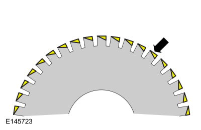
Radial runout is the egg-shaped deviation from a perfect circle and is measured perpendicular to the circumference. On a wheel and tire assembly, this means measuring the center tire tread rib. The center rib is indicative of the condition of the tire as a whole. Total runout is the difference between the maximum-to-minimum gauge reading. The high spot is the location of maximum runout.
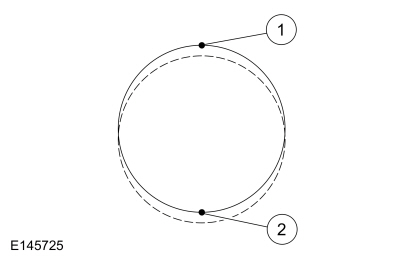
| Item | Description |
|---|---|
| 1 | High spot |
| 2 | Low spot |
Radial Runout Measurement - Loaded Hunter Road Force® Method
NOTE: Diagnosis of tire/wheel vibration should not be performed on tires with less than 322 km (200 mi). Some initial tire/wheel vibration issues (such as flat spotting) may correct themselves after the tires have been in service for 322 km (200 mi). This procedure will assist with the diagnosis of wheel and tire assembly runout and/or force variation issues. This procedure is intended to be used with a Hunter Road Force® balancer that measures the wheel and tire assembly's loaded runout and the tire's radial spring rate. The balancer then converts the runout into pounds of force (termed as Road Force). Measuring loaded runout (Road Force) is more effective than measuring unloaded runout using a dial indicator.
-
Using a tire crayon, record the vehicle position on the inward sidewall of all 4 tires.
-
Remove the wheel and tire assemblies.
REFER to: Wheel and Tire (204-04A Wheels and Tires, Removal and Installation).
-
NOTE: Use only a digital tire pressure gauge any time tire pressures are measured to be sure that accurate values are obtained.
Make sure that the tire pressures are set to the correct pressure as indicated on the tire pressure label.
-
NOTICE: Make sure that the correct wheel balancer adapters are used when mounting the assembly to the wheel balancer. This will prevent the possibility of inducing runout by using incorrect adapters and/or wheel damage.
NOTE: Modern balancers typically list the correct adapter when selecting the vehicle in the application menu. For additional instructions, refer the balancer’s user manual for proper adapter selection.
NOTE: Make sure that the wheel and tire assembly is clean and free of foreign material prior to installation on the balancer.
NOTE: The wheel balancer inflation station must be turned OFF for tires with inflation pressures of 60.0 psi ( 414 kPa) or above.
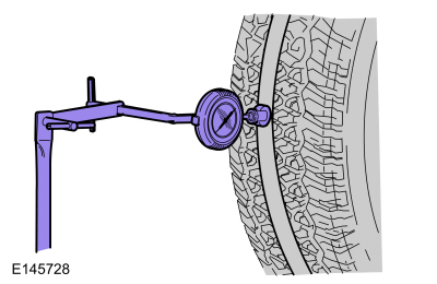
Mount the wheel and tire assembly on a suitable wheel balancer using the correct wheel balancer adapters as shown.
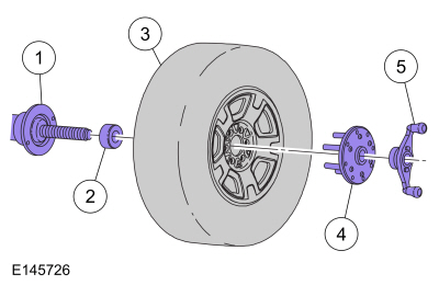
| Item | Description |
|---|---|
| 1 | Wheel balancer |
| 2 | Cone |
| 3 | Wheel and tire assembly |
| 4 | Finger plate |
| 5 | Balancer wing nut |
-
Measure the Road Force®.
- Temporarily mark the high spot and the Road Force® value on the sidewall of the tire. If the wheel and tire assembly Road Force® value is greater than 9 kg (20 lb), carry out the Match Mounting procedure to optimize the wheel and tire assembly.
- If the wheel and tire assembly Road Force® value is 9 kg (20 lb) or less, permanently mark the high spot and the Road Force® value on the inward sidewall of the tire for reference during future wheel and tire service. Balance the assembly and install the wheel and tire on the vehicle using the Wheel-to-Hub Optimization procedure.
Radial Runout Measurement - Dial Indicator Method
NOTE: Diagnosis of tire/wheel vibration should not be performed on tires with less than 322 km (200 mi). Some initial tire/wheel vibration issues (such as flat spotting) will correct themselves after the tires have been in service for 322 km (200 mi).
NOTE: Loaded run-out measurements are the preferred method for verifying tire serviceability. While a dial indicator can be used to optimize the position of the tire on the wheel, the unloaded run-out measurement cannot accurately determine if the tire should be removed from service.
NOTE: The following procedures should be used if normal diagnostics leads to a potential runout issue.
NOTE: Some vehicles may exhibit a wheel and tire vibration caused by excessive runout. Radial runout measurements can be taken using a dial indicator and should be measured with the wheel and tire assembly mounted on a suitable wheel balancer. The dial indicator should be mounted securely to eliminate gauge movement when measuring runout.
NOTE: Use only a digital tire pressure gauge any time tire pressures are measured to be sure that accurate values are obtained.
-
Make sure that the tire pressures are set to the correct pressure as indicated on the VC label.
-
Using a tire crayon, record the vehicle position on the inward sidewall of all 4 tires.
-
Remove the wheel and tire assemblies.
REFER to: Wheel and Tire (204-04A Wheels and Tires, Removal and Installation).
-
NOTICE: Make sure that the correct wheel balancer adapters are used when mounting the assembly to the wheel balancer or damage to the wheel may occur.
NOTE: Make sure that the wheel and tire assembly is clean and free of foreign material prior to installation on the balancer.
NOTE: The wheel balancer inflation station must be turned OFF for tires with inflation pressures of 60.0 psi ( 414 kPa) or above.
Mount the wheel and tire assembly on a suitable wheel balancer using the correct wheel balancer adapters as shown.
| Item | Description |
|---|---|
| 1 | Wheel balancer |
| 2 | Cone |
| 3 | Wheel and tire assembly |
| 4 | Finger plate |
| 5 | Balancer wing nut |
-
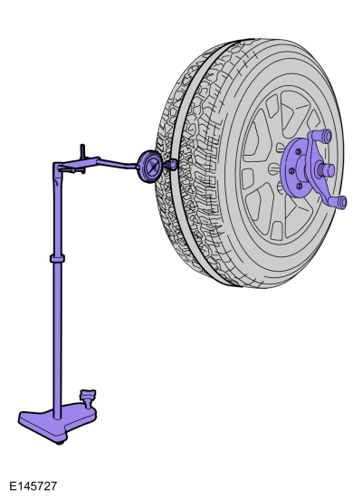
NOTE: Masking tape can be applied on the center tread rib to allow for a smoother measuring surface. Some fluctuation of the gauge reading is expected. Observe the overall sweep of the gauge from the highest to the lowest spot on the tire.
Position a suitable dial indicator and stand with the dial indicator on the center tread rib.
- Rotate the wheel and tire assembly (or wheel) to locate the low spot.
- Adjust the runout gauge to read 0.
- Rotate the wheel and tire assembly one complete revolution to make sure that the low spot has been found and that the dial indicator returns to a 0 reading.
-
While slowly and constantly rotating the wheel and tire assembly (or wheel), measure the radial runout.
- Note the variance (runout) from 0 on the dial of the gauge.
- If the runout reading of a wheel and tire assembly is greater than 1.14 mm (0.045 in), locate and temporarily mark the high spot and runout reading on the sidewall of the tire and carry out the Match Mounting procedure to optimize the wheel and tire assembly.
- If the runout reading of a wheel and tire assembly is 1.14 mm (0.045 in) or less, permanently mark the high spot and the runout reading on the inward sidewall of the tire for reference during future wheel and tire service. Balance the assembly and install the wheel and tire on the vehicle using the Wheel-to-Hub Optimization procedure.
 Description and Operation - Safety Precautions - Overview
Overview
Before beginning any service procedure in this manual, refer to health
and safety warnings in section 100-00 General Information. Failure to
follow this instruction may result in serious personal injury...
 General Procedures - Wheel to Hub Runout Minimization
Check
NOTE:
Wheel-to-hub optimization is important. Clearance between
the wheel and hub can be used to offset or neutralize the Road Force® or
run-out of the wheel and tire assembly...
Other information:
Lincoln Corsair 2020-2026 Service Manual: Diagnosis and Testing - Wipers and Washers
Diagnostic Trouble Code (DTC) Chart Diagnostics in this manual assume a certain skill level and knowledge of Ford-specific diagnostic practices. Module DTC Description Action BCM B130F:12 Run Accessory Control: Circuit Short To Battery GO to Pinpoint Test A BCM B130F:14 Run Accessory Control: Circuit Short To Ground Or Open GO to Pinpoint Test A BCM B13A4:11 Front ..
Lincoln Corsair 2020-2026 Service Manual: Removal and Installation - Timing Chain Tensioner
Removal NOTICE: Do not loosen or remove the crankshaft pulley bolt without first installing the special tools as instructed in this procedure. The crankshaft pulley and the crankshaft timing sprocket are not keyed to the crankshaft. The crankshaft, the crankshaft sprocket and the pulley are fitted together by friction. For that reason, the crankshaft sprocket is also unfastened if the pul..
Categories
- Manuals Home
- 1st Generation Lincoln Corsair Owners Manual
- 1st Generation Lincoln Corsair Service Manual
- Programming the Garage Door Opener to Your Hand-Held Transmitter
- Auto Hold (IF EQUIPPED)
- Exterior Mirrors
- New on site
- Most important about car
USB Port
WARNING: Driving while distracted can result in loss of vehicle control, crash and injury. We strongly recommend that you use extreme caution when using any device that may take your focus off the road. Your primary responsibility is the safe operation of your vehicle. We recommend against the use of any hand-held device while driving and encourage the use of voice-operated systems when possible. Make sure you are aware of all applicable local laws that may affect the use of electronic devices while driving.
USB A