Lincoln Corsair: Four-Wheel Drive Systems - 2.0L EcoBoost (177kW/240PS) – MI4/2.3L EcoBoost (199kW/270PS) / Removal and Installation - All-Wheel Drive (AWD) Module - 2.0L EcoBoost (177kW/240PS) – MI4/2.3L EcoBoost (199kW/270PS)
Removal
NOTE: Removal steps in this procedure may contain installation details.
NOTE: If installing a new all-wheel drive module, it is necessary to upload the module configuration information to the scan tool prior to removing the module. This information must be downloaded into the new all-wheel drive module after installation. Using a diagnostic scan tool, begin the PMI process for the all-wheel drive module following the onscreen instructions.
-
Remove the passenger seat.
Refer to: Front Seat (501-10A Front Seats, Removal and Installation).
-
Remove the lower B-pillar trim panel only.
Refer to: B-Pillar Trim Panel (501-05 Interior Trim and Ornamentation, Removal and Installation).
-
Remove the pin-type retainers and lower the passenger side insulation panel.
 |
-
Disconnect the electrical connector, detach the pin-type retainer and remove the passenger side insulator panel.
 |
-
Release the clips and remove the access cover.
 |
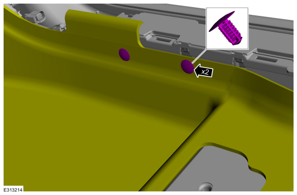
-
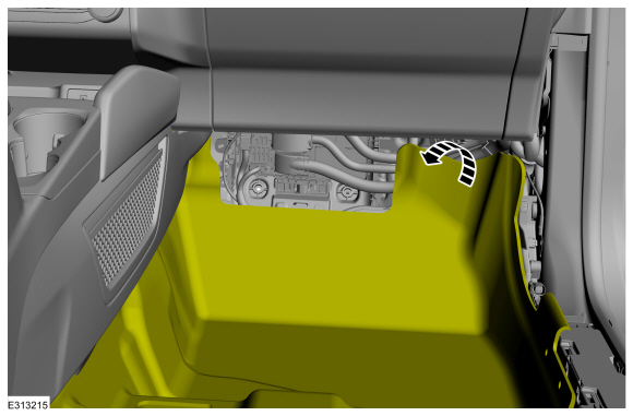
Remove the push pins and position the floor carpet aside.
 |
-
Position the floor carpet aside.
 |
-
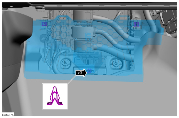
-
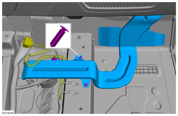
Detach the wiring harness retainer from the HVAC duct.
-
Remove the push pins and the HVAC duct.
-
Detach the wiring harness retainer from the HVAC duct.
 |
-
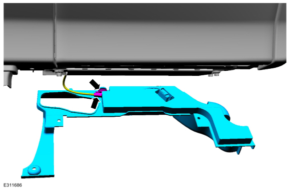
-
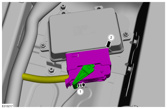
Release the tab from the connector.
-
Disconnect the electrical connector from the module.
-
Release the tab from the connector.
 |
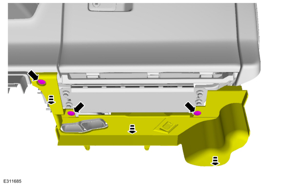
-
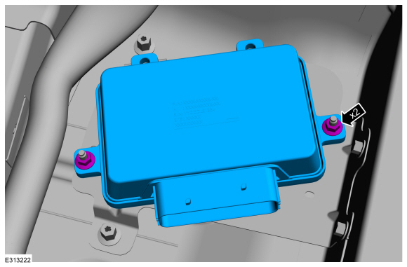
Remove the nuts and the AWD module.
Torque: 89 lb.in (10 Nm)
 |
Installation
-
To install, reverse the removal procedure.
NOTE: Carry out the remaining steps only if installing a new AWD module.
-
NOTE: The 16/17 -digit alpha numeric bar code is located on the label attached to the Rear Drive Unit (RDU).
Using the scan tool, configure RDU bar code to AWD module through the OBD port.
-
Using a diagnostic scan tool, complete the PMI process for the AWD module following the on-screen instructions.
 Diagnosis and Testing - Four-Wheel Drive Systems
Diagnostic Trouble Code (DTC) Chart
Diagnostics in this manual assume a certain skill level and knowledge of Ford-specific diagnostic practices.REFER to: Diagnostic Methods (100-00 General Information, Description and Operation)...

Other information:
Lincoln Corsair 2020-2024 Service Manual: Description and Operation - Differential
Differential Exploded View Item Description 1 Roll pin 2 Pinion shaft 3 Pinion gears 4 Side gears 5 Differential housing Differential Cutaway View and External Sealing Item Description 1 LH halfshaft seal 2 ..
Lincoln Corsair 2020-2024 Service Manual: Removal and Installation - Transmission Support Insulator
Special Tool(s) / General Equipment 303-F070Support Bar, EngineTKIT-1999A-F/LTTKIT-1999A-FM/FLM Removal With the vehicle in NEUTRAL, position it on a hoist. Refer to: Jacking and Lifting - Overview (100-02 Jacking and Lifting, Description and Operation). Remove the following items: Remove the battery tray. Refer to: Battery Tray - 2.0L EcoBoost (177kW/240P..
Categories
- Manuals Home
- 1st Generation Lincoln Corsair Owners Manual
- 1st Generation Lincoln Corsair Service Manual
- Refueling - Gasoline
- Remote Start Settings
- Opening and Closing the Hood
- New on site
- Most important about car
Creating a Vehicle Wi-Fi Hotspot
You can create a Wi-Fi hotspot in your vehicle and allow devices to connect to it for access to the Internet.
 Select the settings option on
the
feature bar.
Select the settings option on
the
feature bar.