Lincoln Corsair: Automatic Transmission - 8-Speed Automatic Transmission – 8F35/8F40 / Diagnosis and Testing - Parameter Identification (PID) Chart
Lincoln Corsair 2020-2026 Service Manual / Powertrain / Automatic Transmission / Automatic Transmission - 8-Speed Automatic Transmission – 8F35/8F40 / Diagnosis and Testing - Parameter Identification (PID) Chart
Diagnostic PID Chart
| PID Acronym | PID Name | Description |
| APP | APP sensor | APP |
| APP1 | APP sensor 1 | APP 1 |
| APP2 | APP sensor 2 | APP 2 |
| AST | Time Since Start | Time (in seconds) since the vehicle was started |
| CLRDIST | Distance since DTC cleared | Distance driven since PCM DTC s were cleared |
| ECT TCM | ECT TCM | Engine coolant temperature data provided to the TCM |
| ENGLOAD | Engine Load | Engine load calculated by PCM |
| ETC_ACT | Electronic Throttle Control Actual | Electronic Throttle Control Actual calculated by PCM |
| FTBRAKE | Foot Brake - Foot brake state used by strategy | Foot brake state used by strategy calculated by PCM |
| GEAR | Gear Commanded by Module | PCM commanded transmission gear |
| GEAR_ENGAGED | Transmission Gear Engaged | Transmission Gear Engaged |
| GEAR_OSC# | Gear Commanded by Output State Control | Output state control commanded gear |
| IN_GEAR | In Gear | Transmission is applying a load to engine |
| ISS_A_QF | Transmission Input Shaft Speed Sensor -A- Quality Factor | Transmission Input Shaft Speed Sensor -A- Quality Factor |
| ISS_A_RAW | Intermediate Speed -A- Raw | Intermediate Speed -A- Raw |
| LINEDSD# | Line Pressure Control Desired | Commanded line pressure |
| LPC | Line Pressure Control (previously shown as PCA) | LPC |
| LPC_AMP# | Line Pressure Control measured in current (previously shown as PCA_AMP) | LPC |
| LPC_F | Line Pressure Control Status (previously shown as PCA_F) | LPC |
| MIL_DIS | The distance travelled since the (MIL) was activated | The distance travelled since the MIL was activated |
| OSS_QF | Transmission Output Shaft Speed Sensor Quality Factor | Fault status for the OSS sensor |
| OSS_RAW | Output Shaft Speed - Raw | Actual speed of the OSS sensor (rpm) |
| PWRT_FUNCMON_A | Powertrain Secondary Monitor/Performance Fault A | Powertrain Secondary Monitor/Performance Fault A |
| PWRT_FUNCMON_B | Powertrain Secondary Monitor/Performance Fault B | Powertrain Secondary Monitor/Performance Fault B |
| REALTIME | Total time (ECU) has been active | ECU Time running |
| RPM | Engine Revolutions Per Minute | Engine rpm input to TCM |
| SHFT_DROP | Shift RPM Drop in Input Shaft Speed Below Expected | Shift rpm drop in input shaft speed below expected |
| SHFT_FLRE | Shift RPM Rise in Input Shaft Speed Above Expected | Shift rpm rise in input shaft speed above expected |
| SHFT_ID | Shift Identification of Shift (PID)s Lag, Time, Flare and Drop | Shift identification of shift PID s lag, time, flare and drop |
| SHFT_LAG | Shift Time Elapsed From 10% to 90% of Complete | Actual time during shift between 10% and 90% complete |
| SHFT_TIME | Shift Time Elapsed From Commanded to 10% Complete | Shift time 0% to 10% complete |
| SHFT_TYP | Shift Type | Shift Type |
| SS_ABS_TC_IN | (Stop-Start) Antilock Brake And Traction Control Summary | (Stop-Start) Antilock Brake And Traction Control Summary |
| SS_CTRL_CRANK_CMD | (Stop-Start) Main Control Crank Command And Hardware Feedback | (Stop-Start) Main Control Crank Command And Hardware Feedback |
| SS_CTRL_STATE | (Stop-Start) Main Control State Machine | (Stop-Start) Main Control State Machine |
| SS_DISABL _00-20 | Stop-Start Feature Disabled | 20 PIDS identifying different reasons Stop-start might be disabled |
| SS_DRVR_INPUTS | (Stop-Start) Monitor Human Input Summary Including Accelerator, Brake, Clutch, Shift Input, Or Cruise Control | (Stop-Start) Monitor Human Input Summary Including Accelerator, Brake, Clutch, Shift Input, Or Cruise Control |
| SS_MON_STATE | (Stop-Start) Monitor State Machine | (Stop-Start) Monitor State Machine |
| SS_MON_TIMER | (Stop-Start) Monitor State Machine Transition Timer | (Stop-Start) Monitor State Machine Transition Timer |
| SS_OUTOP | Start-Stop Coordination | Out of Operation |
| SS_SHIFTER_IN | (Stop-Start) Shift Lever Position Input | (Stop-Start) Vehicle Speed and Powertrain Shaft Speeds Summary |
| SS_SPEED_INPUT | (Stop-Start) Vehicle Speed and Powertrain Shaft Speeds Summary | (Stop-Start) Vehicle Speed and Powertrain Shaft Speeds Summary |
| SS_STRTR_HEAT | (Start-Stop) Starter Motor Heat State | (Start-Stop) Starter Motor Heat State |
| SSPCA | Shift Solenoid Pressure Control A | Commanded pressure for the Shift Solenoid Pressure Control A (SSPCA)/CB12345 |
| SSA_AMP # | Shift Solenoid Pressure Control A | Commanded current for the Shift Solenoid Pressure Control A (SSPCA)/CB12345 |
| SSPCA_F | (SSPCA) Status | Fault status for the Shift Solenoid Pressure Control A (SSPCA)/CB12345 |
| SSPCB | Shift Solenoid Pressure Control B | Commanded pressure for the Shift Solenoid Pressure Control B (SSPCB)/C46R |
| SSB_AMP# | Shift Solenoid Pressure Control B | Commanded current for the Shift Solenoid Pressure Control B (SSPCB)/C46R |
| SSPCB_F | (SSPCB) Status | Fault status for the Shift Solenoid Pressure Control B (SSPCB)/C46R |
| SSPCC | Shift Solenoid Pressure Control C | Commanded pressure for the Shift Solenoid Pressure Control C (SSPCC)/CB37 |
| SSC_AMP# | Shift Solenoid Pressure Control C | Commanded current for the Shift Solenoid Pressure Control C (SSPCC)/CB37 |
| SSPCC_F | (SSPCC) Status | Fault status for the Shift Solenoid Pressure Control C (SSPCC)/CB37 |
| SSPCD | Shift Solenoid Pressure Control D | Commanded pressure for the Shift Solenoid Pressure Control D (SSPCD)/SOWC |
| SSD_AMP# | Shift Solenoid Pressure Control D | Commanded current for the Shift Solenoid Pressure Control D (SSPCD)/SOWC |
| SSPCD_F | (SSPCD) Status | Fault status for the Shift Solenoid Pressure Control D (SSPCD)/SOWC |
| SSPCE | Shift Solenoid Pressure Control E | Commanded pressure for the Shift Solenoid Pressure Control E (SSPCE)/C5678 |
| SSE_AMP# | Shift Solenoid Pressure Control E | Commanded current for the Shift Solenoid Pressure Control E (SSPCE)/C5678 |
| SSPCE_F | (SSPCE) Status | Fault status for the Shift Solenoid Pressure Control E (SSPCE)/C5678 |
| SSPCF | Shift Solenoid Pressure Control F | Commanded pressure for the Shift Solenoid Pressure Control F(SSPCF)/CB28 |
| SSF_AMP# | Shift Solenoid Pressure Control F | Commanded current for the Shift Solenoid Pressure Control F(SSPCF)/CB28 |
| SSPCF_F | (SSPCF) Status | Fault status for the Shift Solenoid Pressure Control F(SSPCF)/CB28 |
| SST_D | SelectShift™ Transmission - Down Switch Input | SelectShift™ transmission-down switch input |
| SST_U | SelectShift™ Transmission - Up Switch Input | SelectShift™ transmission-up switch input |
| TC_SLIPACT | Torque Converter Slip Actual | Actual difference between engine speed and turbine speed, measured in rpm |
| TC_SLIPDSD | Torque Converter Slip Desired | PCM commanded difference between engine speed and turbine speed, measured in rpm |
| TCC | Torque Converter Clutch Solenoid | Commanded pressure for the TCC |
| TCC AMP# | Converter Pressure Control | Commanded current for the TCC |
| TCC_F | Torque Converter Clutch Pressure Control Fault | Fault status for the TCC |
| TCC_OSC# | Output State Control of Torque Converter | Output state control commanded pressure to the TCC |
| TCC_RAT | Torque Slip Ratio | Actual speed ratio of torque converter (1.0 = fully engaged) |
| TCS_DEPRES | Transmission Control Switch Pressed | TCS status |
| TFPS_A | Transmission Fluid Pressure Sensor A | Voltage reading that represents the A clutch pressure. |
| TFPS_B | Transmission Fluid Pressure Sensor B | Voltage reading that represents the B clutch pressure. |
| TFT | Transmission Fluid Temperature | TFT |
| TFTV | Transmission Fluid Temperature | TFT voltage |
| TFT_QF | Transmission Fluid Temperature Sensor Quality Factor | Fault status for TFT sensor |
| TR | Transmission Range | TR |
| TR_CRANK | Transmission Range Input Allowing Engine Start | TR |
| TR_PARK_STAT | Transmission Park Position Sensor Status | Transmission Park Position Sensor Status |
| TR_PAWL_NOTPARK | Transmission Park Pawl | Transmission park pawl control has not been moved to the park position since it was last in the manual park override position. |
| TR_QF | Transmission Range Quality Factor | Fault status for TR sensor |
| TRAN_RAT | Gear Ratio Measured | Actual transmission gear ratio |
| TRANS_VOLT_A | Transmission Supply Voltage Control State | Transmission supply voltage |
| TSS_QF | Turbine Shaft Speed Sensor Quality Factor | Fault status of the TSS sensor (rpm) |
| TSS_RAW | Turbine Shaft Speed - Raw | Actual speed of the TSS sensor (rpm) |
| VPWR_PCM | Module supply voltage | PCM supply voltage |
| VSS | Vehicle Speed | Vehicle Speed |
| VSS_HR | Vehicle Speed High Resolution | Vehicle Speed High Resolution |
| WARMUPS | Number Of Warm-ups Since (DTCs) Cleared | Number Of Warm-ups Since (DTCs) Cleared counter |
 Diagnosis and Testing - Leakage Inspection
Leak Check Test
With the vehicle in NEUTRAL, position it on a hoist.REFER to: Jacking and Lifting - Overview (100-02 Jacking and Lifting, Description and Operation)...
 Diagnosis and Testing - DTC Chart and Pinpoint Tests - 2.0L EcoBoost (177kW/240PS) – MI4
Diagnostic Trouble Code (DTC) Chart
Diagnostics in this manual assume a certain skill level and knowledge of Ford-specific diagnostic practices.REFER to: Diagnostic Methods (100-00 General Information, Description and Operation)...
Other information:
Lincoln Corsair 2020-2026 Service Manual: General Procedures - Differential Draining and Filling
Draining With the vehicle in NEUTRAL, position it on a hoist. Refer to: Jacking and Lifting - Overview (100-02 Jacking and Lifting, Description and Operation). Remove and discard the RDU fluid fill plug. Remove and discard the RDU fluid drain plug and allow the RDU fluid to drain...
Lincoln Corsair 2020-2026 Service Manual: Removal and Installation - Hands-Free Liftgate Actuation Upper Sensor
Removal NOTE: Removal steps in this procedure may contain installation details. With the vehicle in NEUTRAL, position it on a hoist. Refer to: Jacking and Lifting (100-02) . Remove the push pins, the screws and the lower bumper cover bracket assembly...
Categories
- Manuals Home
- 1st Generation Lincoln Corsair Owners Manual
- 1st Generation Lincoln Corsair Service Manual
- Programming the Garage Door Opener to Your Garage Door Opener Motor
- Interior Lamps
- Selecting a Drive Mode. DRIVE MODES
- New on site
- Most important about car
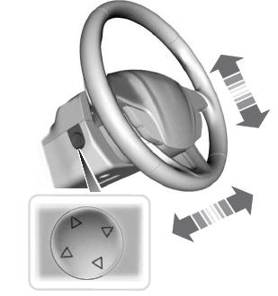
Adjusting the Steering Wheel - Vehicles With: Power Adjustable Steering Column
WARNING: Do not adjust the steering wheel when your vehicle is moving.
Note: Make sure that you are sitting in the correct position.
Copyright © 2026 www.licorsair.com